Roof Design
Aim:
To a given roof styling, create essential flanges and reinforcement.
Objective:
- To design the automotive roof based on the given styling surface and to analyze the prepared model to check the manufacturability and the feasibility of the design.
- To perform the section modulus study for the master sections and create for front roof rail, Bow roofs and center roof rail.
- To create the Ditch area and to perform the draft analysis.
Introduction to Roof:
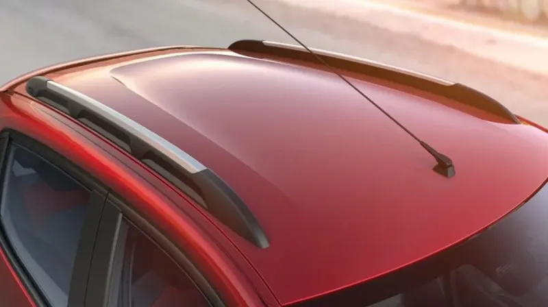
- An automotive roof or car top is the portion of the automobile that sits above the passenger compartment, protecting the vehicle occupants from Sun, Wind, Rain and other external element.
- Under the styling surfaces that’s is seen from the outside, there are many other structures under the roof that contributes to its strength and stability.
- The number of such reinforcement structures/supports differ with respect to the size of the vehicle.
- They are primarily installed on the flatter areas of the roof to enhance the strength.
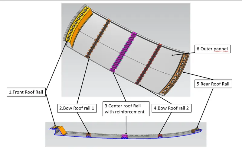
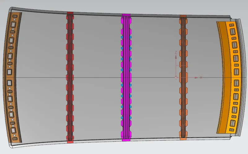
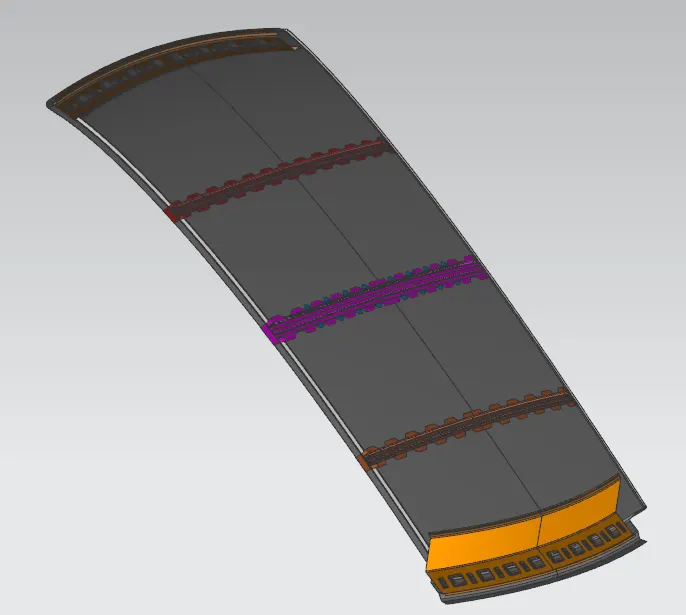
- They are the Front Roof Rail, Rear Roof Rail, Center Rail and Bow Roof Design which are given Mastics and spot welded to the roof flanges & ditch are and improve NVH value by increasing the strength of the roof of using mastics sealants
Types of Car Roofs:
- Convertible roofs.
- Hard Tops
- Sun roofs.
- T- Tops.
- Target tops.
- Vinyl roofs
Design Consideration of roof:
- Visibility Criteria
- Head Clearance
- Curvature Study
- Heat Distortion and snow load criteria
- Draft Analysis
- Safety Parameters
Types of Roof Rails:-
- Front Roof Rail,
- Rear Roof Rail,
- Center Rail and
- Bow Roof
- Outer pannel
1.Front Roof Rail:-
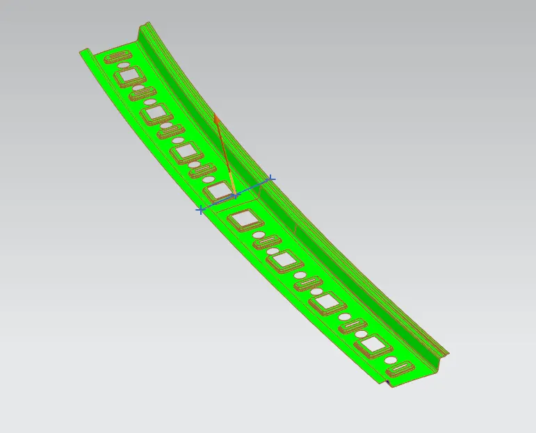
- The front roof rail is the one that joins the windshield glass, body side outer, and inner panel.
- Here the front roof rails are designed based on the master section given

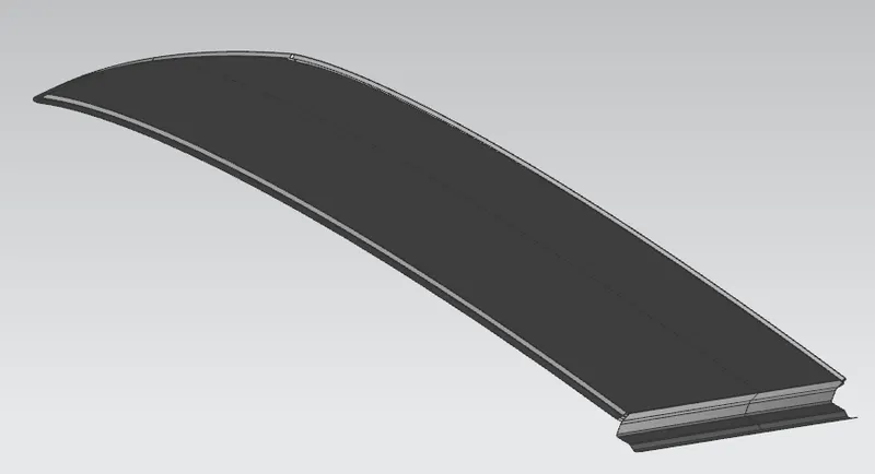
2.Roof Outer Panel:
3.Rear roof rail:
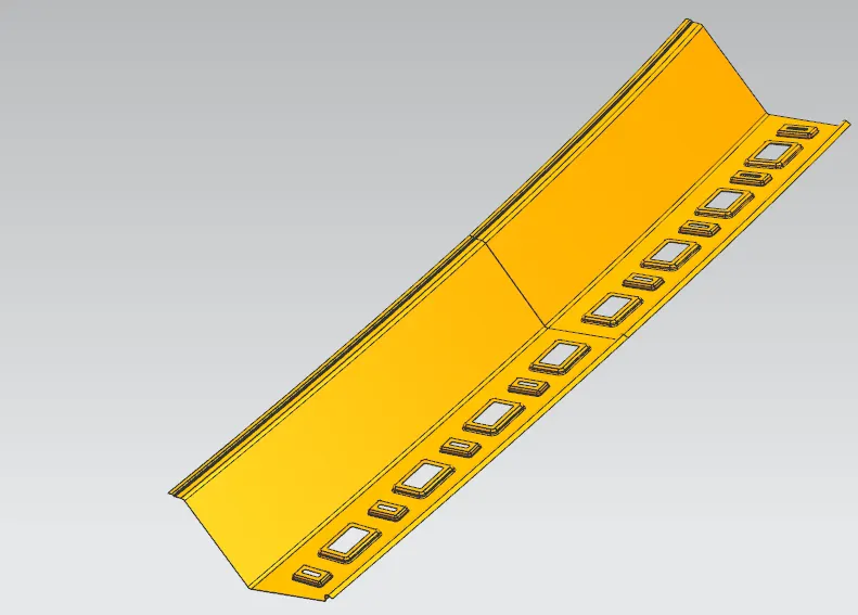
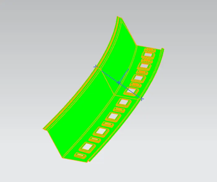
- Just as the front rail roof, the rear rail roof provides reinforcement to the rear part of the car roof.
- Similar to the front rail roof, the rear roof rail is to be designed considering the rear visibility criteria and the rear passenger’s headroom clearance.
4.Central Roof rail with reinforcement:
- Central roof rail helps in providing effectively support to the flat area of the roof as it is more susceptible to failure under the action of load.
- Generally central roof rail is placed at the center of the roof which is connected to the B-pillar support structure.
- This central roof rail helps in the strength to the roof during the roll-over test.

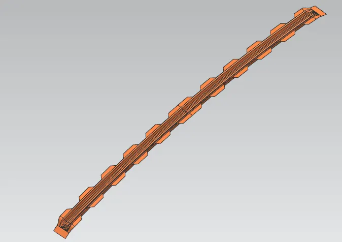
5.Bow roof rail 1 & 2:
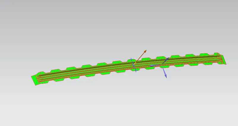
- The Bow roofs are given to improve the torsional stiffness and load-bearing capacity of the roof structure.
- The number of bow roofs presents depends on the overall size of the roof.
- Presently in this project, two bow roofs are provided.
6.Joining process:-
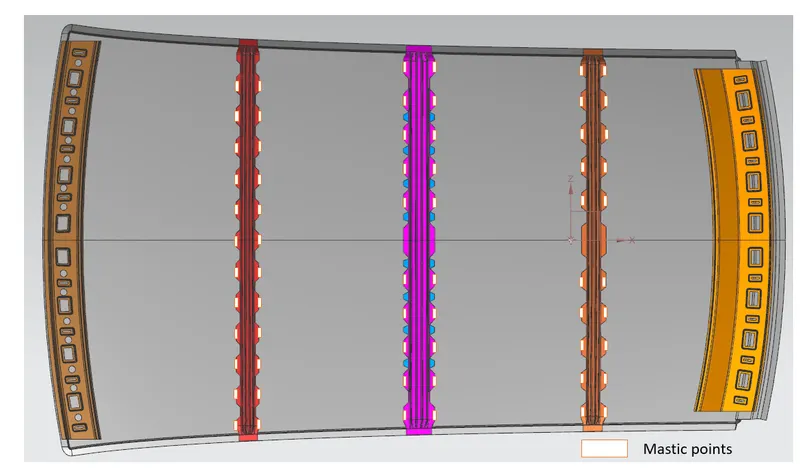
- Mastic is introduced between the roof outer panel and the reinforcement for joining.
- Where ever the mastic is introduced there is a remarkable strength increase.
- Spot welding is also introduced to join the reinforcements and outer panel.
Design Calculation of Roof:
To make sure the roof design passes the Analysis test some of the criteria to be considered before the design of bow rails under the roof. They are,
- Heated Distortion study on the roof
- Snow Load Condition
1.Heated Distortion study on the roof:
- The heat distortion study plays a major role in sheet metal usage.
- Heat distortion temperature is the temperature limit above which the MATERIAL cannot be used for the structural applications.
- This study is used to predict the heat distortions temperature at the material where it start to soften when exposed to a fixed load at elevated temperature.
- In order to avoid bending or damages on the roof, based on the heat distortion temperature, this study will predict the bow roof position which helps to strengthen the roof.
BOW – roof prediction study
W= [1.73x10 ^ (-3) x L] + [1.85 x 10^ (-8) x (R^2)/t] + [1.10 x 10^ (-3) x1] – 2.68
Where’
L = Roof strength in X- Direction [mm] (Roof dimension in 0 – Y)
R = Roof curvature
R = 2 (Rx*Ry) / (Rx + Ry)
Rx = X Curvature
Ry = Y curvature
t = Roof plate thickness [mm]
I = Bow Roof span [mm]
Judgement Condition: OK < 2.7 > 3.1
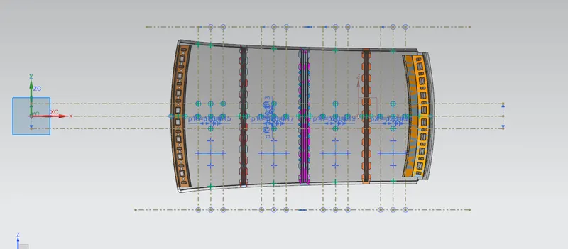
Here we have to find out Rx and Ry values. To find out
- Create a sketch on Top roof and draw a horizontal line at a center.
- Then offset this line below 300mm and called it as _3y line.
- From the _3y line offset 100 mm above and below and convert all these line into reference line.
- Draw the vertical lines at the middle of each reinforcements and offset it at 100 mm both sides.
- Intersection point is created where the lines are met.
- Project there points the outer roof panel.
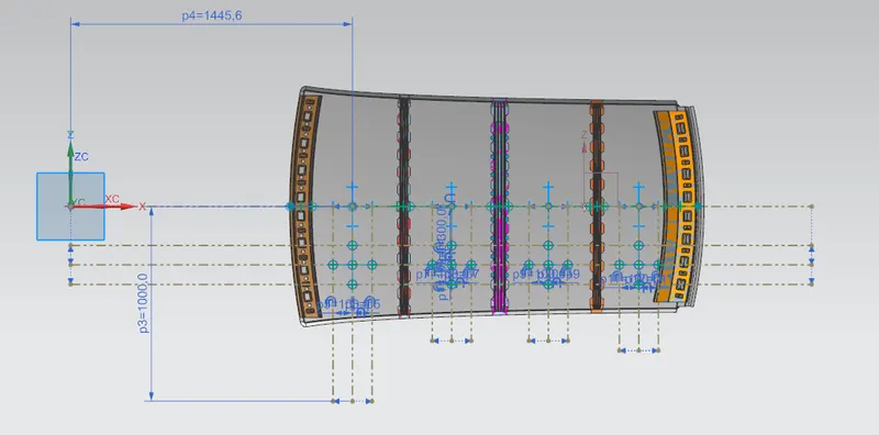

From the above table, it can be concluded that all values of w<2.7 and also not w>3.1 so thus infer that the current positioning of the bow row is good in the state as per the design and found
2.Snow Load Condition
- This test is done to know-how is the roof is behaving when there is snow over.
- Normally due to the snow weight, the dent will happen.
- But the roof should be designed in such a way that when the snow is removed the roof should go to its original position.
- These are basic requirements for the snow load criteria.
Qr = [ Iy x t2] / [ α x s x [ ( Rx + Ry) / 2] 2 x 10⁻⁸]
α= My x L x 2 x 10-12,
My = Y (Ly - Y )
Judgement Condition = Qr ≥ 3.1
250 ≤ s ≤ 380
t = roof thickness [mm]
Ly = Distance between the front and rear roof rails on the vehicle along the OY [mm]
Lx = Distance between the left and right end of the roof on the Roof Bow [mm]
Y = Distance of front Roof rail to roof bow [mm]
s = Distance for which roof Bow bears divided load [mm]
s= L1/2 + L2/2
Iy = Geometrical moment of inertia of Roof Bow ( Y cross-section ) [mm4]
Rx = Lateral direction curvature radius of roof panel Y cross-section on Roof bow [mm]
Roof panel curvature radius of the length Lx in Front View
Ry = Longitudinal direction curvature radius of the roof panel X cross-section on Roof Bow [mm]

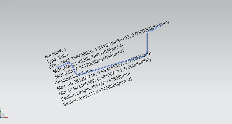
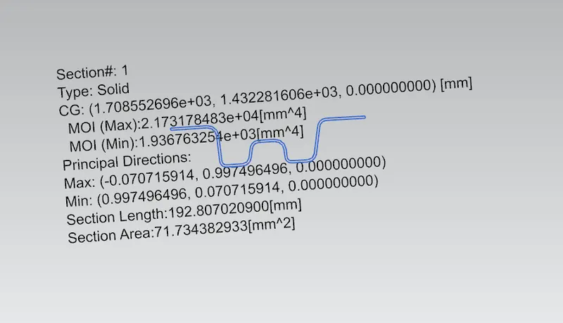
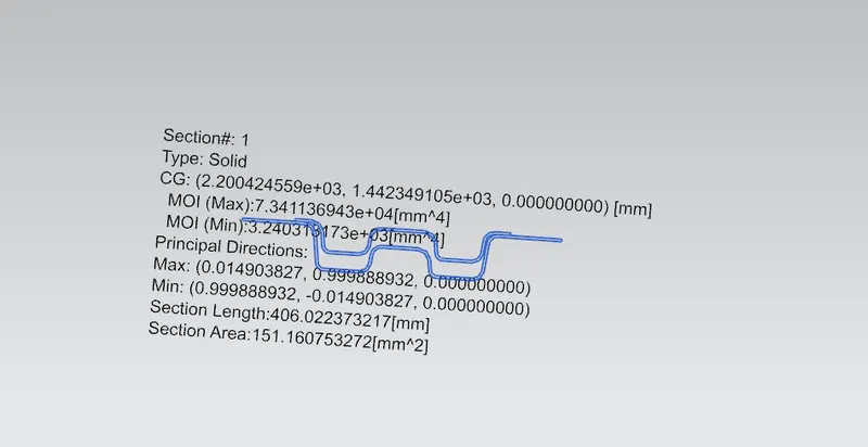
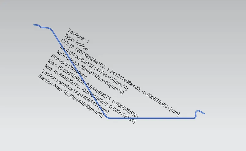
To find MOI by section modulus analysis:-
- Front Roof Rail
- Bow Roof
- Center Rail
- Rear Roof Rail
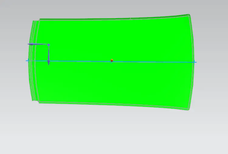
Draft Analysis :
- The Draft analysis command enables you to detect if the part you drafted will be easily removed.
- This type of analysis is performed based on color ranges identifying zones on the analyzed element where the deviation from the draft direction at any point, corresponds to specified values.
1.Roof Outer Panel:
2.Front Roof Rail:-
5.Bow roof rail 1 & 2:
4.Rear roof rail:
5.Central Roof rail
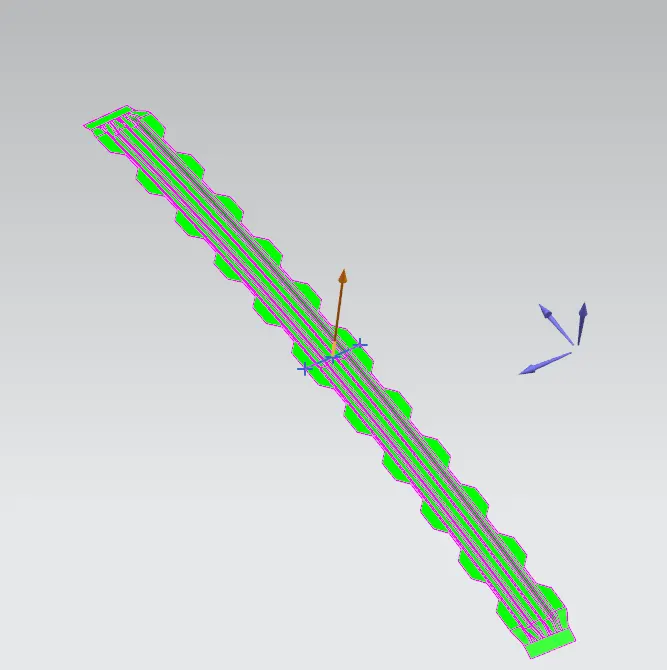
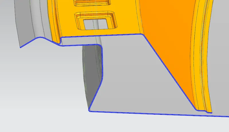
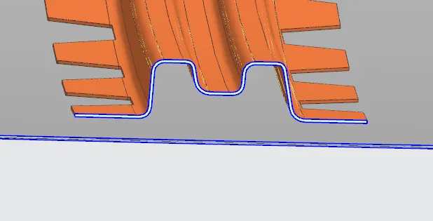
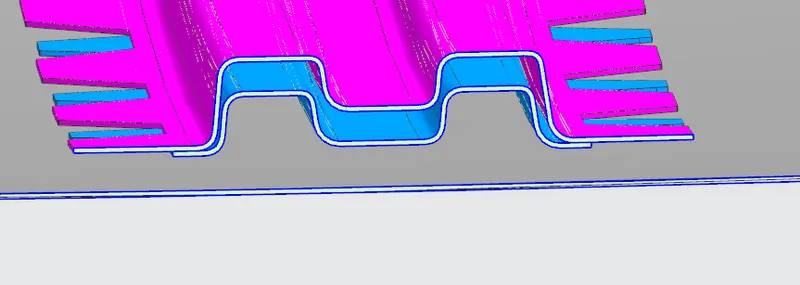
Sections of each parts:
Rear roof rail
Bow roof rail 2
center roof rail with reinforcement
Bow roof rail 1
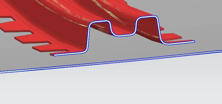
front roof rail
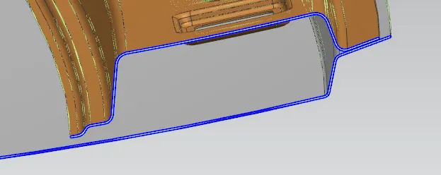
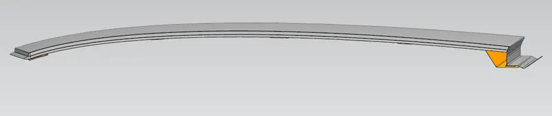
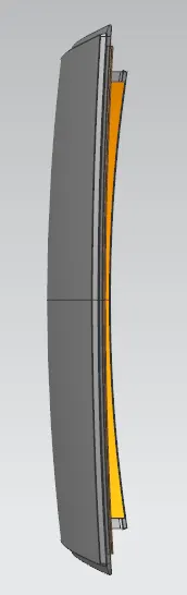
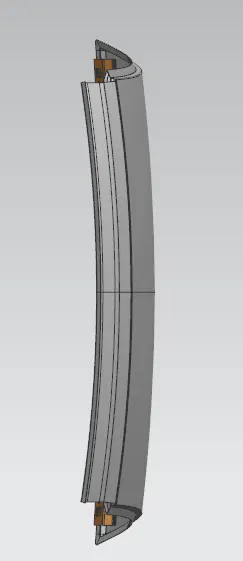
assembly view

Conclusion:
- Thus the required reinforcement and the ditch area for the roof were designed and developed from the given styling.
- The curvature study was done after performing calculation for the Heat Distortion and Snow load conditions with the position criteria met for all reinforcements.
- Further the section modulus study was conducted and Draft analysis were done for each reinforcement successfully.