Roof Design
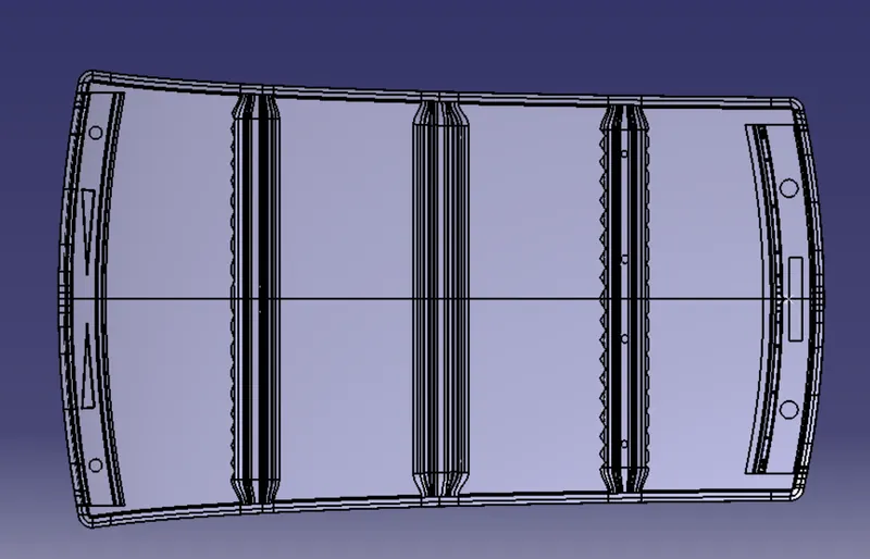
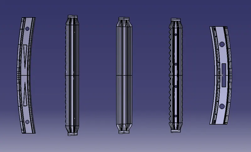
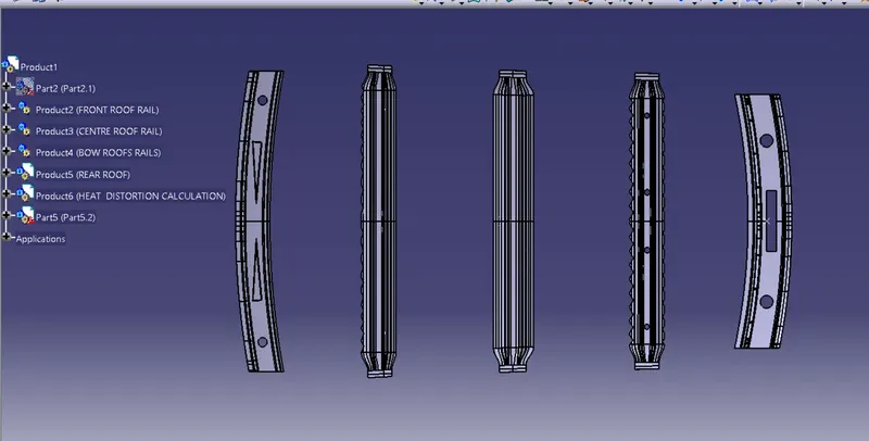
AIM:Create the necessary flanges and reinforcement for the aforementioned car roof styling, including the ditch area, frontal roof rail, rear roof rail, center roof rail, and bow roofs.
Perform a roof curvature study and calculate the heat distortion and snow load criterion in order to establish and justify the position of the bow roofs.
INTRODUCTION:The part of a car that protects its occupants from the sun, heat, wind, and other elements outside is called the roof.
Roof Design
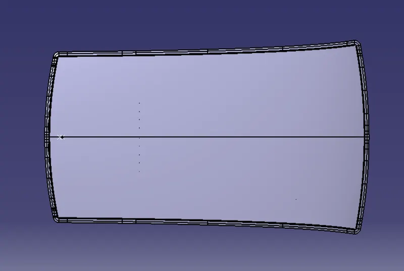
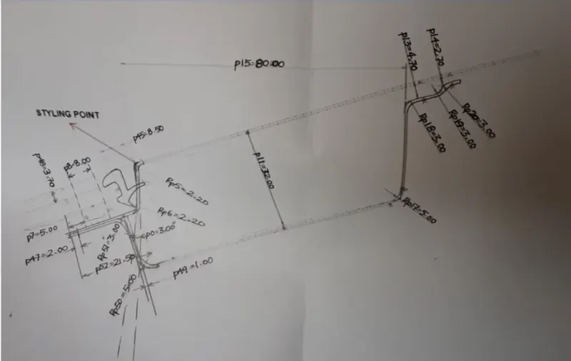
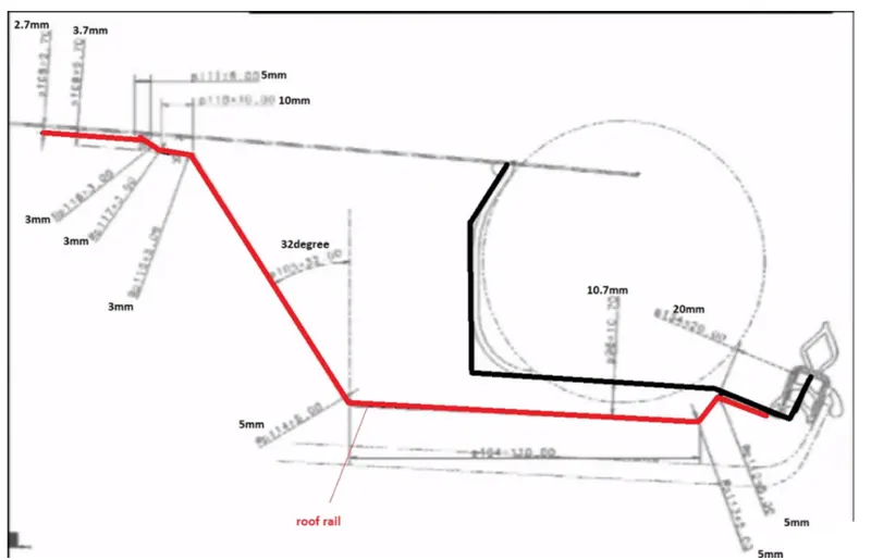
The given surface is A-class, and we must design the roof surface using this A-class and master sections. There are two master sections, one for the front end rail roof and one for the rear rail roof:
Reinforcements and Design
The extended portion of the main roof that is obscured by other BIW panels is known as the Ditch Area.Spot welds are used to join the roof's rail supports to the Ditch Area.because it is not a surface for styling and remains hidden.
Front Roof Rail
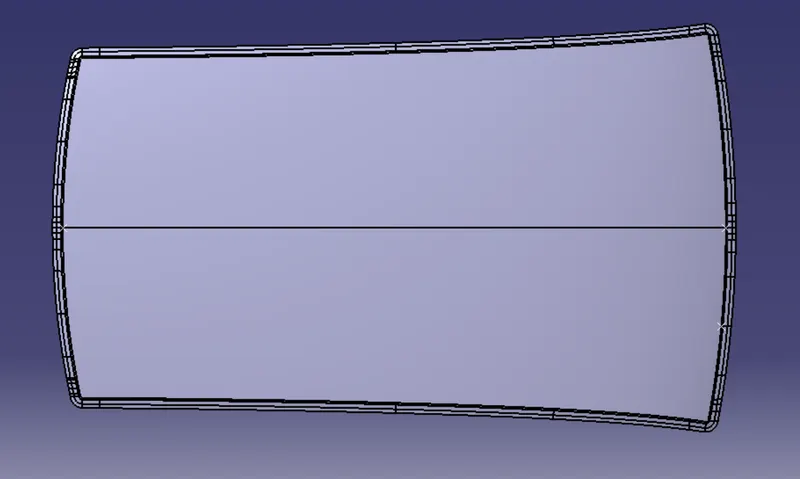
The support holds the windshield glass together.Exterior panels on the body and interior panelsIt typically has a thickness of 0.75 mm.The extract offset from the roof surface is represented by the windshield end flanges.The visibility criteria are taken into consideration when selecting the lowest flange.Spot welding is used at the windshield end, and Mastics sealants are used to join the other end to the roof, which also adds strength.
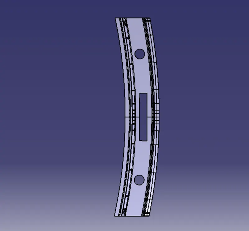
Rear roof rail
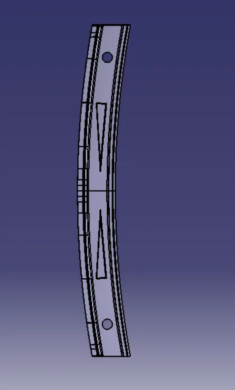
It is the support that is joined to the back door and the Body side outer and the inner panels. it is usually made from body side outer scrap and therefore the thickness of the rail is 0.75mm. Similar to the Front roof rail design. We have to take into consideration the rear headroom clearance and the rear visibility criteria while designing the rear roof rail from the backdoor design and also taken into consideration od the required clearance. Spot welds are applied at the back door end of the rail and the other end is joined with the roof using Mastic sealants.
Bow Roof Rails
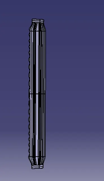
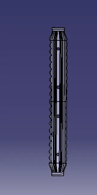
The center roof rail and the bow roof rail must be designed with headroom clearance and visibility criteria in mind, just like the other design.Spot welding is not used to join these roof rails here.Since center roofs are completely positioned under the styling surface of the roof, mastic sealants are instead used at both ends.Embossing is done on the rails to make them stronger.Different styling and a thickness of 0.75 mm have been used to reduce the weight of the material.
Reinforcement centre rail
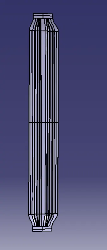
It is the really supporting bar for the rooftop.They absorb energy during a collision by serving as an attachment point for crossbars and other devices that secure loads carried on the vehicle's roof.It has a thickness of 1 mm.
Analysis
- CURVATURE STUDY:
It is done to justify the positioning of the bow roofs. There are mainly two criteria to fulfil Heat distortion criteria
Snow load criteria
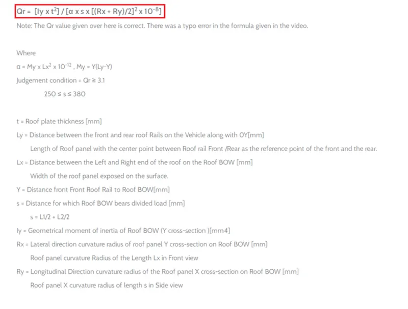
Heat distortion formula :
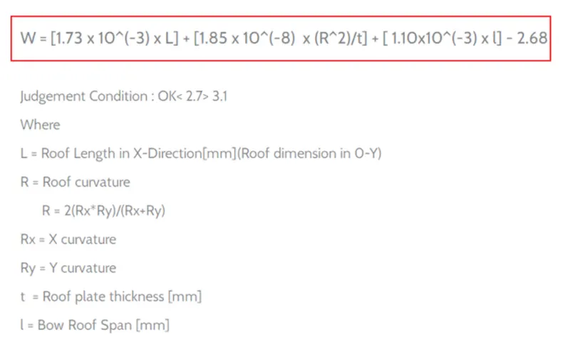
From the model we have the value shown in fig:
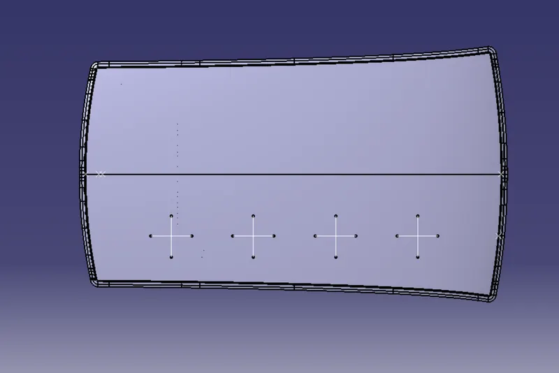
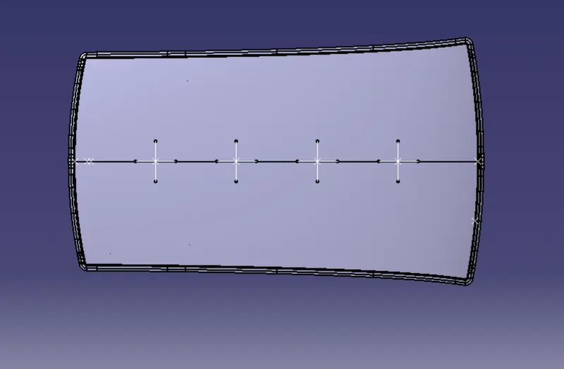
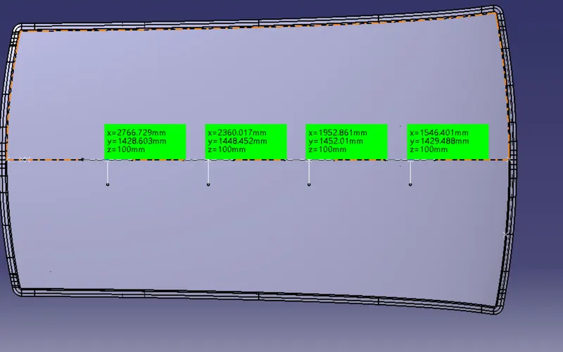
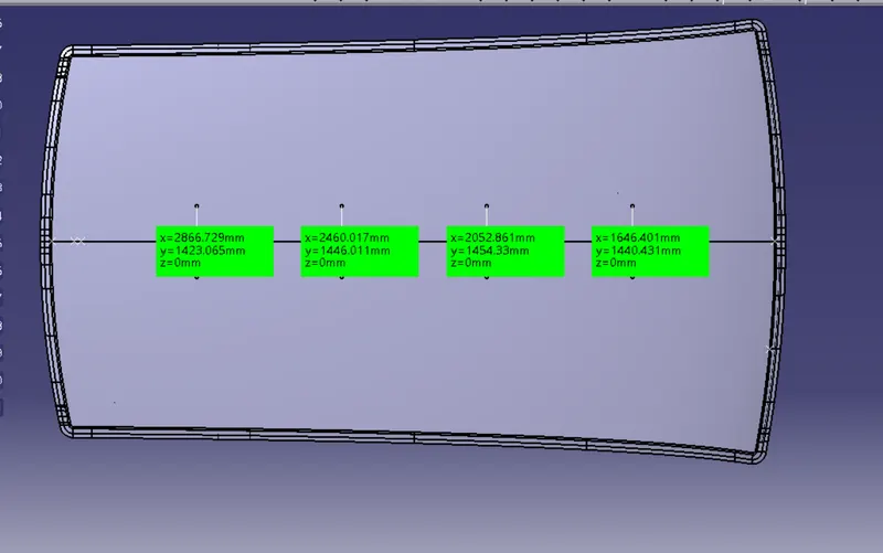
We then project four points onto the roof surface and join these points using the spline option after intersecting points on the line.
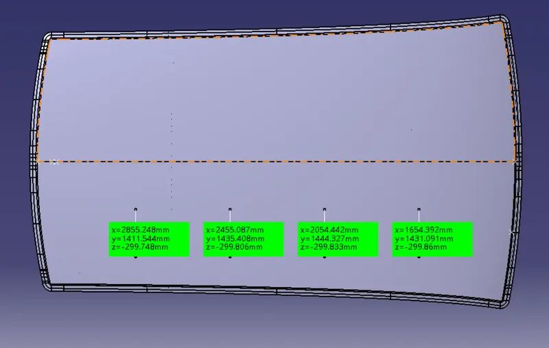
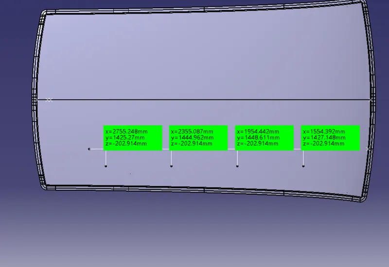
The level line is Rx and the upward line is our Ry.
The radius of curvature for the hood component along the x-axis is given below:
The radius of curvature of the hood component along the Y-axis is below:
Snow Load Criteria:
After creating all the lines we intersect points and project these points on the hood by using the spline curve option this will look like given below figure:
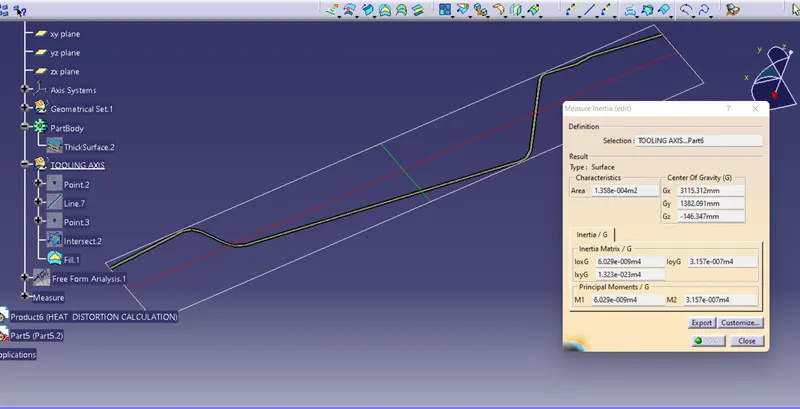
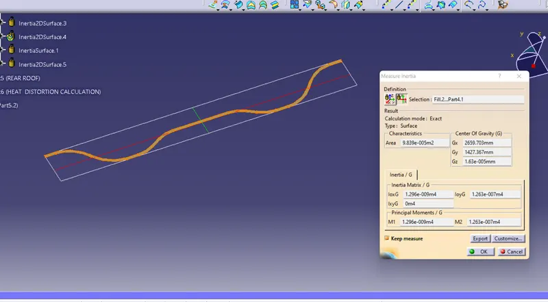
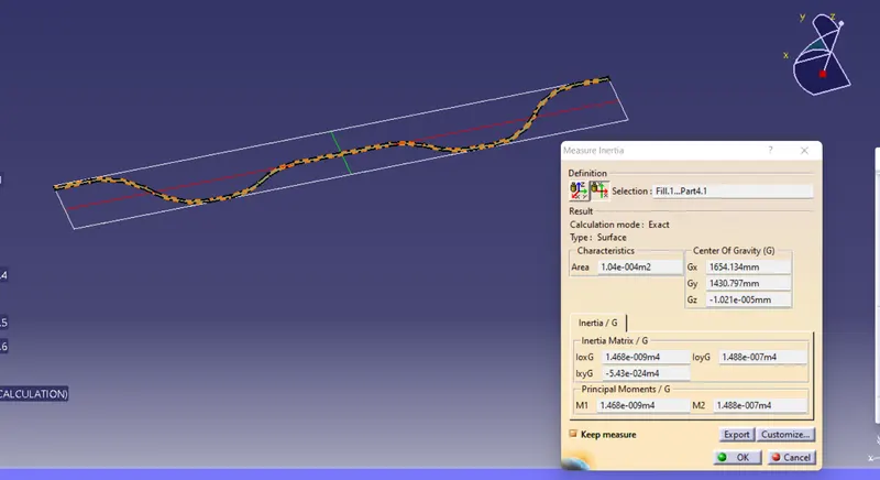
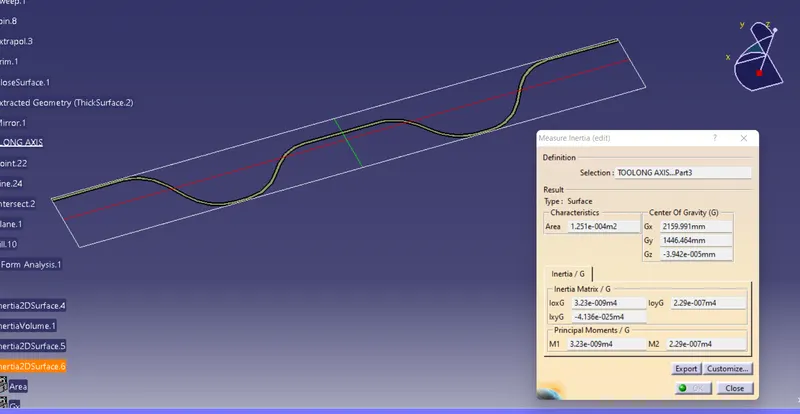
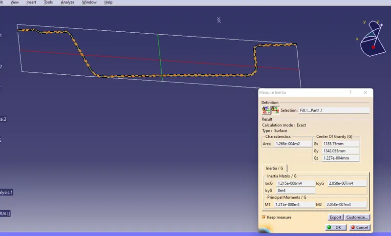
For the Geometrical Moment of inertia, we need a section at each rail, and shown in the figure below:
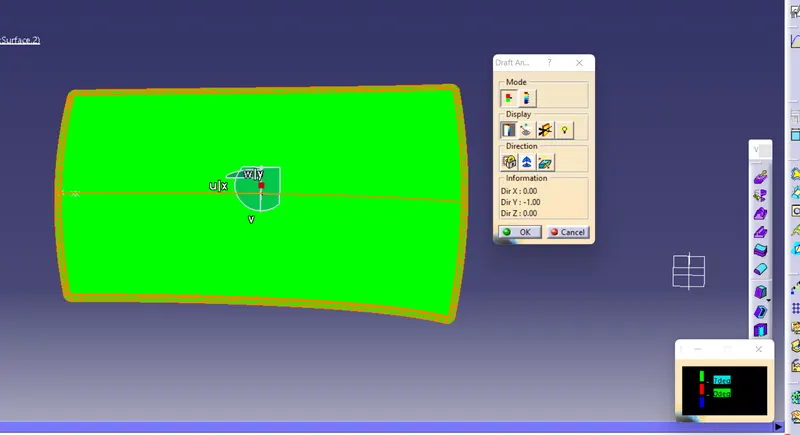
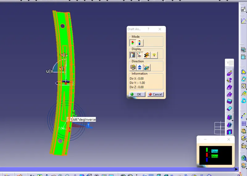
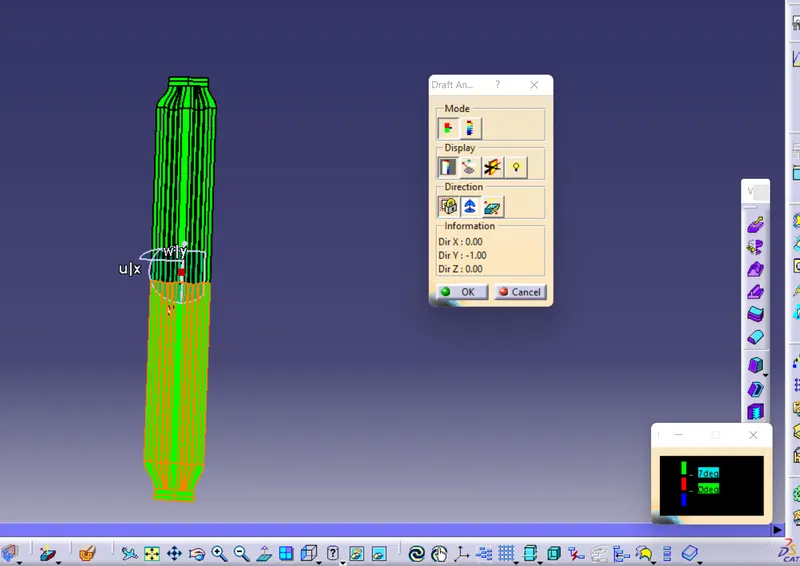
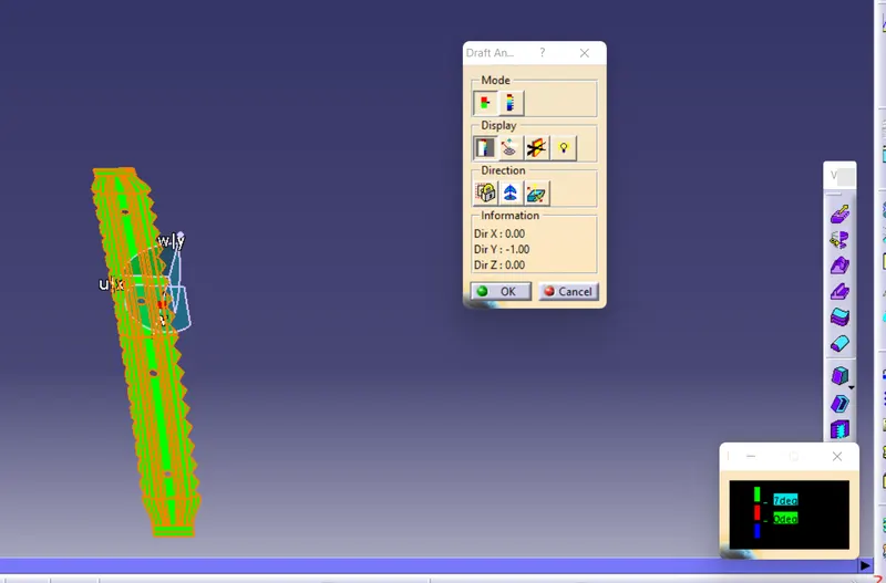
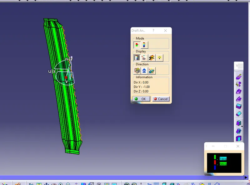
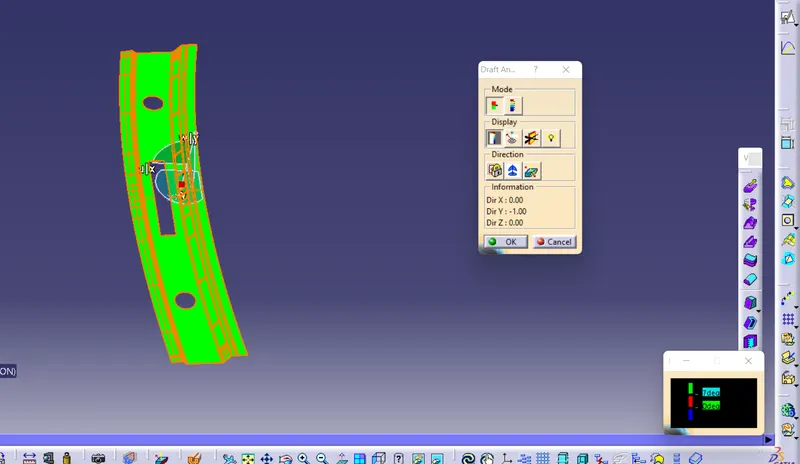
Draft of the Analysis: Draft examination is a strategy for checking the draft point on different countenances of a section in a specific course.It ought to be higher than 7 degrees.draft analyzing command that informs you if your design or model has a draft angle in a particular tool direction.
If the part meets the requirements, it is highlighted in green; otherwise, it is highlighted in blue or red.
The preliminary analysis for the Roof, Front Roof Rail, Rear Roof Rail, Bow Roofs, and Reinforcement Center is depicted in the figures below.
.
Results:The final model is depicted in the figure after the roof, front roof rail, rear roof rail, bow roofs, and reinforcement roof center were designed in accordance with the Master section and the design parameter for the given class A surface. below.