Roof Design
OBJECTIVE:
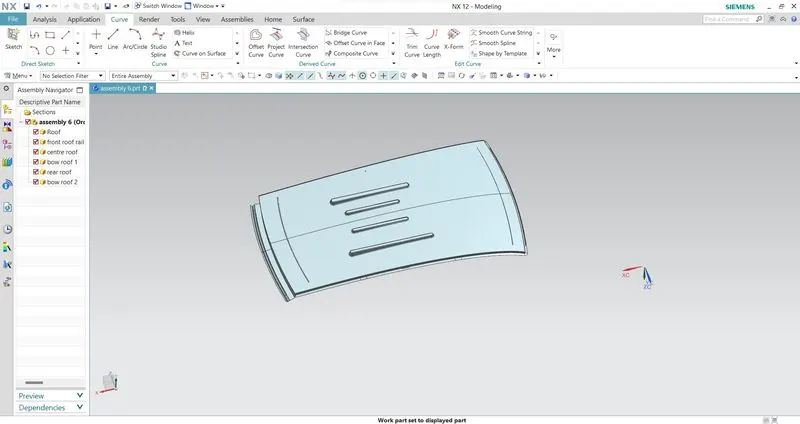
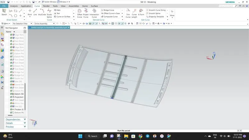
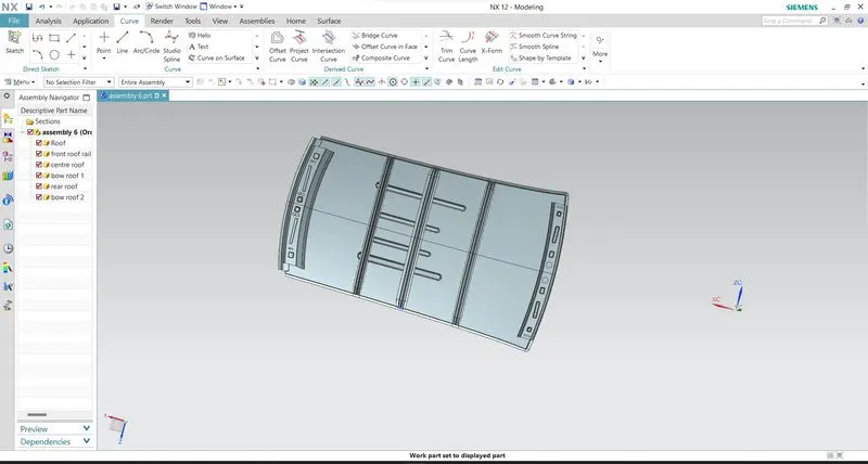
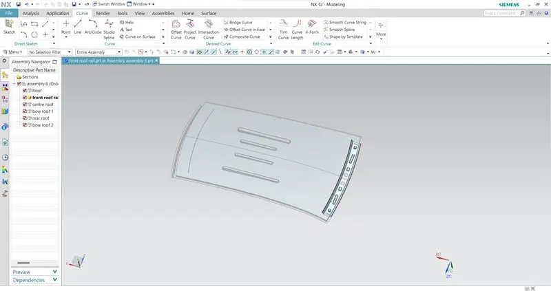
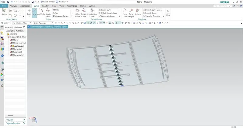
1.Main objective of the project is to create the Roof Sheetmetal design in NX cad, and also designing Front roof rail, rear roof rail, bow roof front, bow roof rear, center roof rail and Reinforcement are creating to build the strong roof.
2.Do curvature study on Roof and performance calculations for Heat distortion and Snow load criteria to determine the position of the Bow roofs.
3.Finding the moment of inertia and section modulus for Bow-roofs and center roof rail.
4.And, also finding the Draft Analysis of each part.
SOFTWARE USED: NX 12.0
- To design the Sheetmetal ROOF in NX by using some Solid/Surface features.
- NX Software is a flexible and powerful integrated solution that helps you deliver the products faster and efficiently.
- NX Cad software is widely used automotive, aerospace, thermal power station. Because of it is having modelling, drafting and manufacturing platform.
INTRODUCTION:
An automobile roof or car top is the portion of an automobile that sits above the passenger compartment, protecting the vehicle occupants from sun, wind, rain, and other external elements.
When it is seeing from outside of the car, it is just closing the top portion. But in design point of view, it is hard to create the design. Because of you have to create no of support rails for enough strength to withstand the load. Bow roofs are primarily fixed in flatter region to enhance strength.
Front roof and rear roof rails are fixed to the ditch area using spot weld operation. But front, rear bow roof and center roof rails are fixed to roof using mastic sealants. We don’t want so much gap between roof rails and bow roof area. So, we reducing the NVH issues.
DESIGN CONSIDERATION OF ROOF:
- Visibility criteria
- Head room clearance
- Bow roof position
- Heat distortion and Snow load criteria
- Draft analysis
ROOF CRUSH TEST:
OVERVIEW OF THE TEST:
Roof strength evaluations consist of a quasi-static test conducted on a vehicle’s roof in a manner similar to tests used to judge compliance with Federal Motor Vehicle Safety Standard 216 (Office of the Federal Register, 2009). The main differences between the procedure specified by the Insurance Institute for Highway Safety (IIHS) and that specified by the U.S. federal government are that the IIHS procedure are,
- Specifies testing one side of a vehicle’s roof
- Does not include a headroom criterion
- Specifies testing to a given displacement instead of a given force level
- Specifies setting the vehicle’s pitch angle during testing based on the measured on-road pitch angle.
An overall rating is assigned based on the peak strength-to-weight ratio (SWR) measured within 127 mm of plate displacement.
CURB WEIGHT MEASUREMENT:
Curb weight values used for calculating the SWR are based on IIHS measurements of a vehicle, not the manufacturer’s specified curb weight.
Vehicle curb weight is measured with full fluid levels using scales manufactured by Longacre Racing Products (Computer scales DX series 72634).
TEST VEHICLE SELECTION:
For information on how we select vehicles for our crash test programs, including how we define typically equipped vehicles, see Test Vehicle Selection (IIHS, 2021). Whenever possible, the vehicle acquired for testing is the same vehicle used for the curb weight measurement.
At times, it is necessary to test a vehicle that does not meet the IIHS definition of a typically equipped vehicle, and the curb weight measurement is applied from another vehicle that does meet the definition. In these cases, the test vehicle does not differ from our typically equipped vehicle definition in any way that might influence the roof strength (e.g., a vehicle with a sunroof would not be tested if the typically equipped vehicle lacks this option).
Once the test vehicle has been acquired, either the driver or passenger side of the vehicle is selected for testing. For most vehicles, the test side is chosen at random. However, for roof designs that appear asymmetrical, engineering judgment is used to select the side of the roof that may result in a lower peak force.
TEST VEHICLE PREPARATION:
With the vehicle on a level surface, the on-road pitch angle at the front door sill is measured on both sides of the vehicle. Unless the vehicle manufacturer requests otherwise, roof racks and other nonstructural items that may be contacted during the test are left as installed from the factory.
Any trim or other components are removed if they interfere with supporting the vehicle along its rocker panels. For vehicles with vertical pinch weld flanges on the bottom of the rocker panels, the vehicle support system consists of one I-beam (HR A-36 W4X13) for each rocker panel.
Each I-beam has a clamping system incorporated on the top that is tightened against the pinch weld flange to clamp the system in place (Figures 1 and 2). When the pinch weld flange has a bend that prevents supporting the sill with one I-beam, more than one I-beam can be used on each side of the vehicle.
For vehicles with no pinch weld flange, or with a nonvertical flange angle that precludes clamping, mounting by another method may be necessary, such as that described in the National Highway Traffic Safety Administration’s Laboratory Test Procedure (2006).
Prior to testing, the front-row seat back on the side being tested is reclined to prevent interaction with the crushing roof. Rear seats are latched in their upright position. All windows are closed and doors are locked.
TESTING OF ROOF:
Roof strength evaluations are conducted on a quasi-static test system manufactured by MGA Research Corporation (Figure 3).
The system consists of an upright assembly and an attached loading head that can be fixed at varying heights from the ground as well as at pitch angles ranging from −5 to +5 degrees to accommodate testing on the driver or passenger side.
The roll angle is permanently fixed at 25 degrees. Four hydraulic actuators control the movement of the platen along two linear guides. The entire system is mounted on a T-slot bed plate anchored to the floor of the test facility.