Roof Design
AIM: To design the roof of a car and front roof rail, bow roofs, center roof and rear roof rail using SIEMENS NX CAD software and perform calculations to determine the position of the Bow roofs.
What is a Roof?
An automobile roof or car top is the portion of an automobile that sits above the passenger compartment, protecting the vehicle occupants from sun, wind, rain, and other external elements.
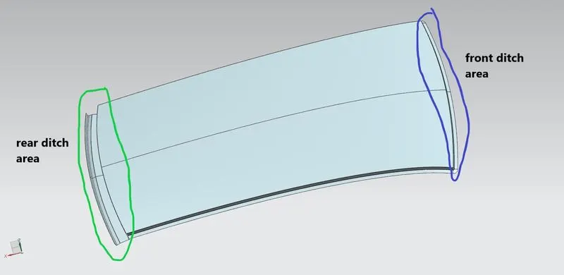
Front roof and rear roof rails are fixed to the ditch area using spot weld operation. But the front and rear bow roof and center roof rail are fixed to the roof using mastic sealants. We don’t want so much gap between roof rails and bow roof area. So, we are reducing the NVH issues.
DESIGN CONSIDERATION OF ROOF:
- Visibility criteria
- Head room clearance
- Bow roof position
- Heat distortion and Snow load criteria
- Draft analysis
Design of the Roof
Roof
Front Roof Rail
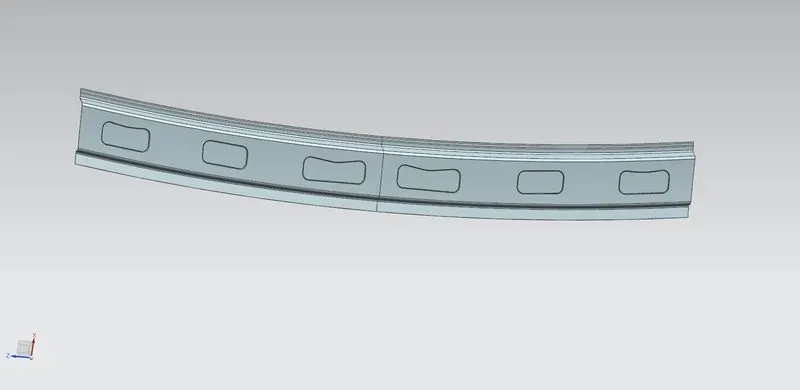
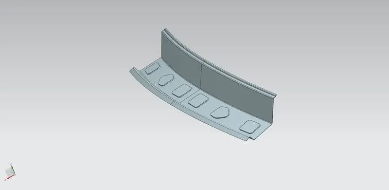
Front roof rail is used to provide strength to the roof panel front and it also acts as link between windshield glass, roof panel and headliner(interior trim). Headroom clearance and visibility are two important criteria for the driver and both of them depends upon the front roof rail dimensions, hence it is important to select appropriate dimensions for the roof rail.
Bow Roof Front
Center Roof
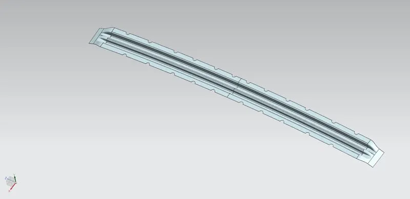
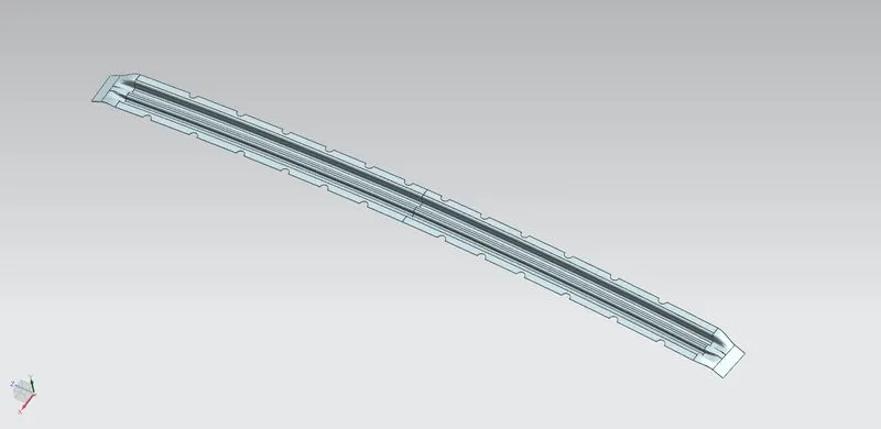
Reinforcement Center roof rail is effective support to the flat area structure roof. Because of center area of roof is more susceptible to failure under action of load. Usually, center roof rails are fixed at the center of the roof for connecting to the B Pillar support structure.
Bow Roof Rear
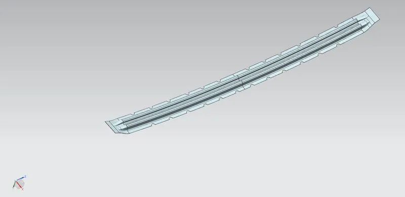
The bow roofs are given to the improve the torsional stiffness and load bearing capacity of the roof structure. When number of bow roofs are given by the roof dimension. Longer the roof area we have to give the more bow roof to the structure.
Positioning of the bow roofs are decided by the curvature study. The Heat distortion and Snow load criteria are checked to analyze the bow roof position by various condition.
Mastics are given on each roof to join them with the outer roof.
We have to place the bow roofs on a flatter surface also.
Rear Roof Rail
Bow–Roof Prediction Formula
W = [1.73 x 10^ (-3) x L] + [1.85 x 10^ (-8) x (R^2)/t] + [ 1.10x10^ (-3) x l] - 2.68
Where,
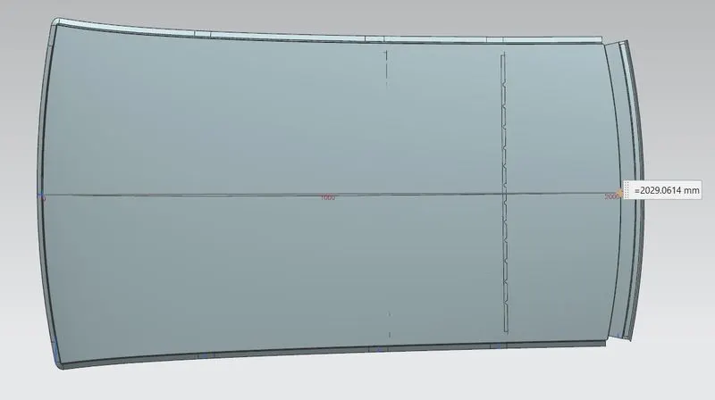
L = Roof Length in X-Direction[mm] (Roof dimension in 0-Y)
R = Roof curvature
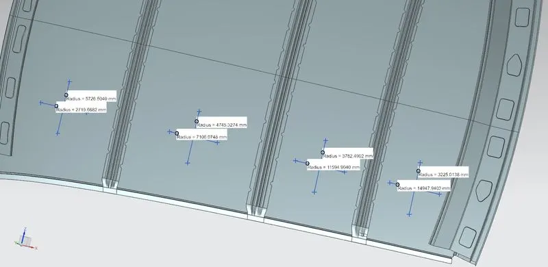
R = 2(Rx*Ry)/ (Rx + Ry)
Rx = X curvature
Ry = Y curvature
t = Roof
plate thickness [mm]
l = Bow Roof Span [mm]
Judgment Condition
OK< 2.7
Rx and Ry
L
|
Roof Rails |
Rx |
Ry |
R |
L |
t |
l |
W |
Result |
|
Front roof – Bow Roof |
5726.5 |
2719.66 |
3687.86 |
2029.06 |
0.75 |
441.89 |
1.65 |
OK |
|
Bow Front _ Center Roof |
4745.32 |
7106.07 |
5690.56 |
2029.06 |
0.75 |
529.62 |
2.21 |
OK |
|
Center Roof – Bow Rear |
3782.49 |
11594.9 |
5704.16 |
2029.06 |
0.75 |
344.12 |
2.01 |
OK |
|
Bow Rear – Rear Roof |
3225.01 |
14947.94 |
5305.38 |
2029.06 |
0.75 |
289.61 |
1.84 |
OK |
From this above table we can conclude that all the bow roofs are placed on right positions. Because the value of W is less than 2.7 in all cases which satisfy our given condition.
Snow Load Prediction Formula
Qr = [Iy x t2] / [α x s x [(Rx + Ry)/2]2 x 10-8]
Where,
α = My x Lx2 x 10-12, My = Y(Ly-Y)
t = Roof plate thickness [mm]
Ly = Distance between the front and rear roof Rails on the Vehicle along with 0Y[mm]
Length of Roof panel with the center point between Roof rail Front /Rear as the front and rear reference point.
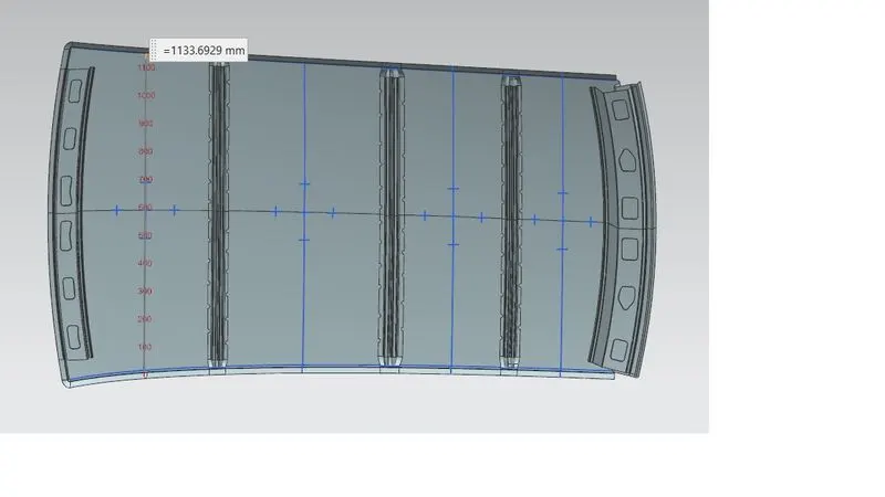
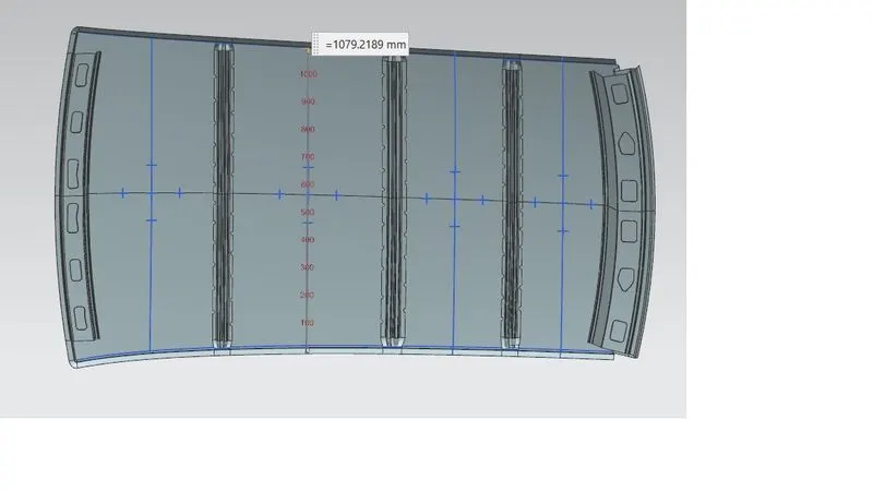
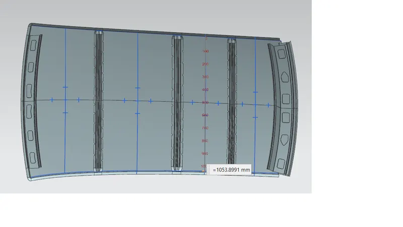
Lx = Distance between the Left and Right end of the roof on the Roof BOW [mm]
The width of the roof panel is exposed on the surface.
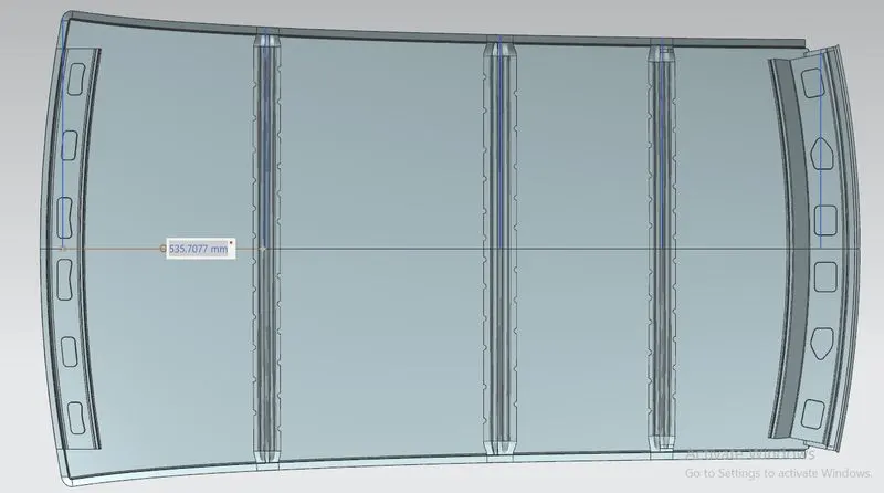
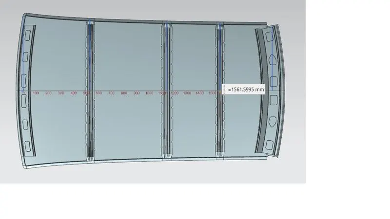
Y = Distance from Front Roof Rail to Roof BOW [mm]
s = Distance for which Roof BOW bears divided load [mm]
s = L1/2 + L2/2
Iy = Geometrical moment of inertia of Roof BOW (Y cross-section) [mm4]
Rx = Lateral direction curvature radius of roof panel Y cross-section on Roof BOW [mm]
Roof panel curvature Radius of the Length Lx in Front view
Ry = Longitudinal Direction curvature radius of the Roof panel X cross-section on Roof BOW [mm]
Roof panel X curvature radius of length s in side view
Judgment condition
Qr ≥ 3.1
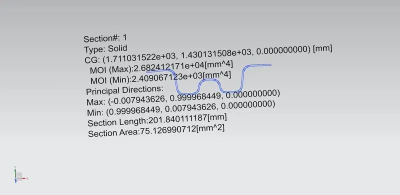
Bow Roof Front Inertia
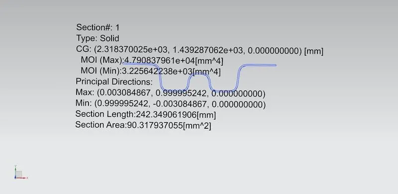
Center Roof Inertia
Bow Roof Rear Inertia
We have to take minimum Moment of Inertia.
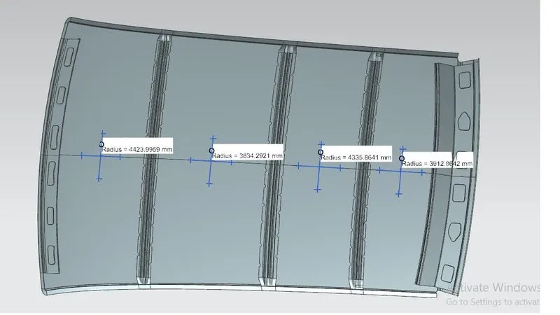
Rx
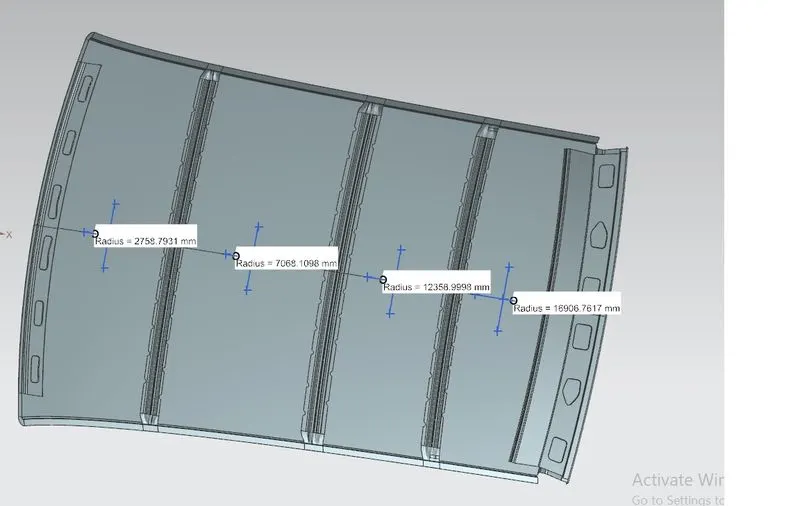
Ry
L1
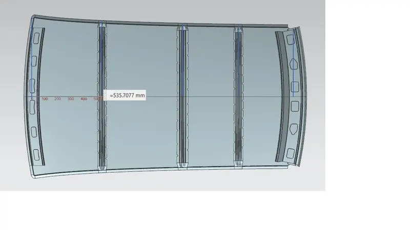
L2
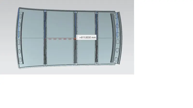
L3
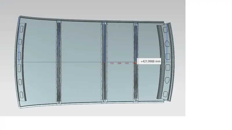
L4
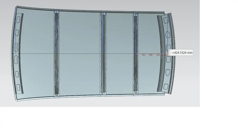
Lx1
Lx2
Lx3
Ly
Y1
Y2
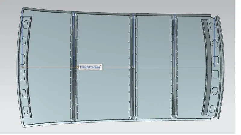
Y3
| Roof Rails | Iy | Lx | Ly | L1 | L2 | Y | Rx | Ry | t | s | My | α | Qr | Result |
| Front Roof - Bow Front | 2409.06 | 1133.69 | 2029.06 | 535.7 | 611 | 535.7 | 4423.99 | 2758.79 | 0.75 | 573.45 | 799992.95 | 1.028 | 18.85 | ok |
| Bow Front - Center Roof | 3225.64 | 1079.21 | 2029.06 | 611 | 421.99 | 1142.81 | 3834.29 | 7068.1 | 0.75 | 516.49 | 1012815.363 | 1.17 | 10.1 | ok |
| Center Roof - Bow Rear | 2580.99 | 1053.89 | 2029.06 | 421.99 | 424.15 | 1561.59 | 4335.86 | 12358.99 | 0.75 | 423.07 | 729996.47 | 0.81 | 6.08 | ok |
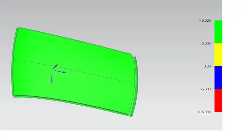
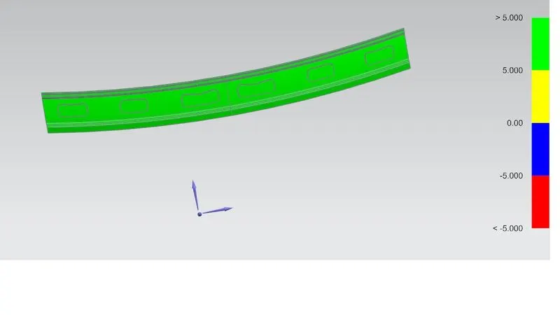
Draft Analysis
The Draft Analysis command enables you to detect if the part you drafted will be easily removed. This type of analysis is performed based on color ranges identifying zones on the analyzed element where the deviation from the draft direction at any point, corresponds to specified values.
Roof Outer Panel
Front Roof Rail
Rear Roof Rail
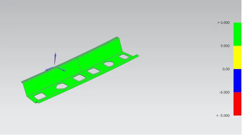
Bow Roof Front
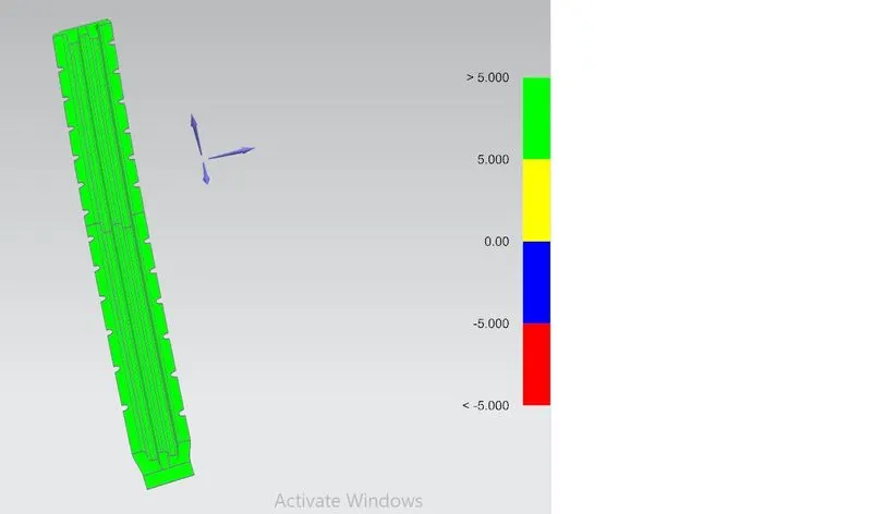
Center Roof
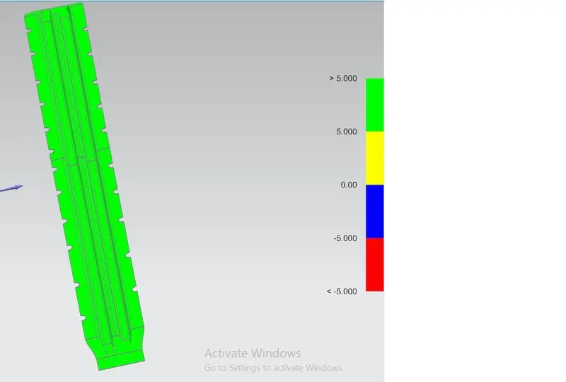
Bow Roof Rear
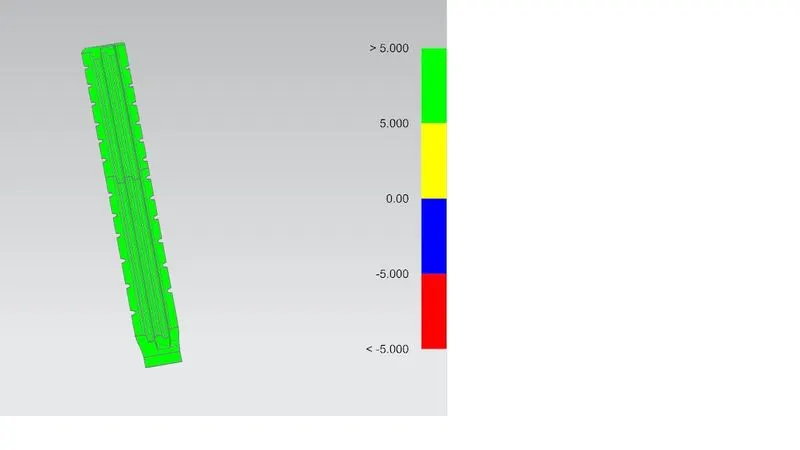
Complete Roof Design

Conclusion
A complete Roof is designed for the given data with the help of NX CAD software.