Roof Design
INTRODUCTION
An automobile roof or car top is the portion of an automobile that sits above the passenger compartment, protecting the vehicle occupants from sun, wind, rain, and other external elements.
Vehicle roofs can be subjected to high heat conditions or load during snowy conditions. To make the roof withstand these conditions, various calculations are done. This ensures the safety of the passengers in the vehicle.
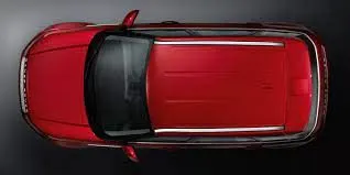
Fig: Shows the roof of an automobile.
OBJECTIVES
For the given roof styling, create an assembly by developing the essential flanges for the outer roof and creating the reinforcements.
DESIGN CONSIDERATION
-
Visibility criteria
-
Head clearance
-
Curvature study
-
Hear distortion and snow load criteria
-
Draft analysis.
DESIGN AS PER MASTER SECTION
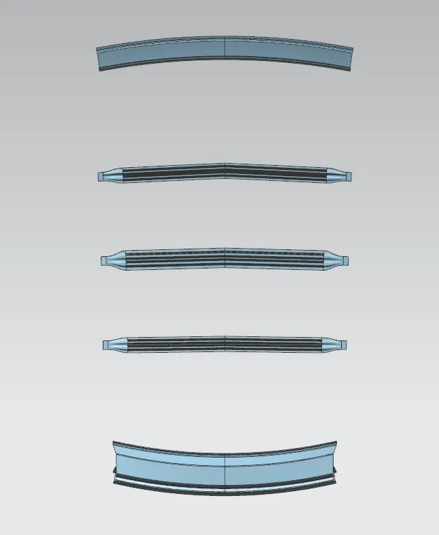
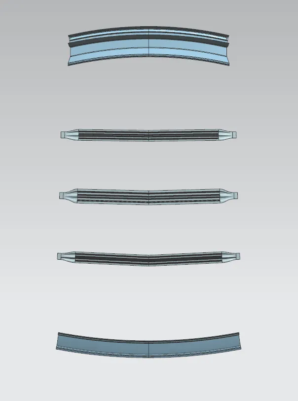
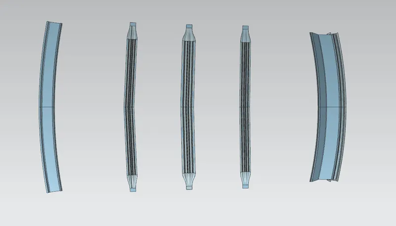
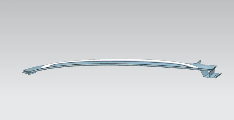
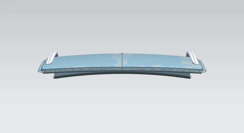
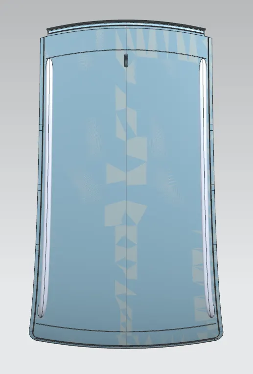
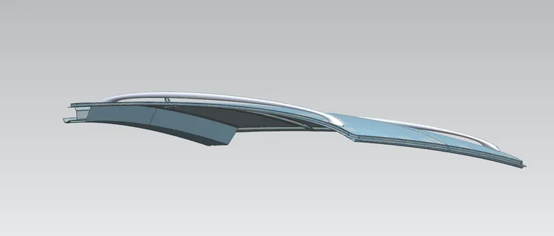
Fig:the design made as per the master section.
CALCULATIONS
CALCULATIONS FOR HEAT DISTORTION CURVATURE STUDY:-
Formula used:- W = [1.73 x 10^(-3) x L] + [1.85 x 10^(-8) x (R^2)/t] + [ 1.10x10^(-3) x l] - 2.68
Where,
L = Roof Length in X-Direction[mm](Roof dimension in 0-Y)
R = Roof curvature
R = 2(Rx*Ry)/(Rx+Ry)
Rx = X curvature
Ry = Y curvature
t = Roof plate thickness [mm]
l = Bow Roof Span [mm]
Value obtained as per design.
| Rx | Ry | R | l | L | T | W | Criteria |
| 2500.765 | 5740.252 | 3483.798 | 478.44 | 2037.04 | 0.75 | 1.669739 | ok |
| 6497.011 | 4897.75 | 5585.152 | 319.24 | 2037.04 | 0.75 | 1.964693 | ok |
| 9978.09 | 4101.864 | 5813.764 | 314.47 | 2037.04 | 0.75 | 2.023726 | ok |
| 13952.15 | 3378.314 | 5439.524 | 468.1 | 2037.04 | 0.75 | 2.088837 | ok |
Judgment Condition
OK< 2.7
CALCULATIONS FOR SNOW LOAD CRITERIA:-
Formula used:- Qr = [Iy x t2] / [α x s x [(Rx + Ry)/2]2 x 10-8]
Where,
α = My x Lx2 x 10-12 , My = Y(Ly-Y)
t = Roof plate thickness [mm]
Ly = Distance between the front and rear roof Rails on the Vehicle along with 0Y[mm]
Length of Roof panel with the center point between Roof rail Front /Rear as the front and rear reference point.
Lx = Distance between the Left and Right end of the roof on the Roof BOW [mm]
The width of the roof panel is exposed on the surface.
Y = Distance front Front Roof Rail to Roof BOW[mm]
s = Distance for which Roof BOW bears divided load [mm]
s = L1/2 + L2/2
Iy = Geometrical moment of inertia of Roof BOW (Y cross-section )[mm4]
Rx = Lateral direction curvature radius of roof panel Y cross-section on Roof BOW [mm]
Roof panel curvature Radius of the Length Lx in Front view
Ry = Longitudinal Direction curvature radius of the Roof panel X cross-section on Roof BOW [mm]
Roof panel X curvature radius of length s in Side view
Inertia values
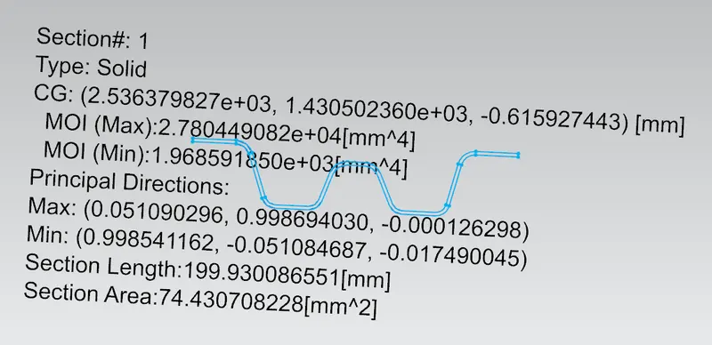
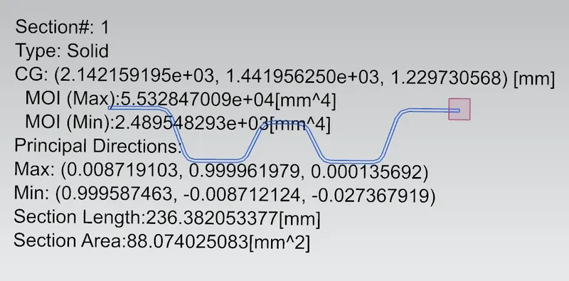
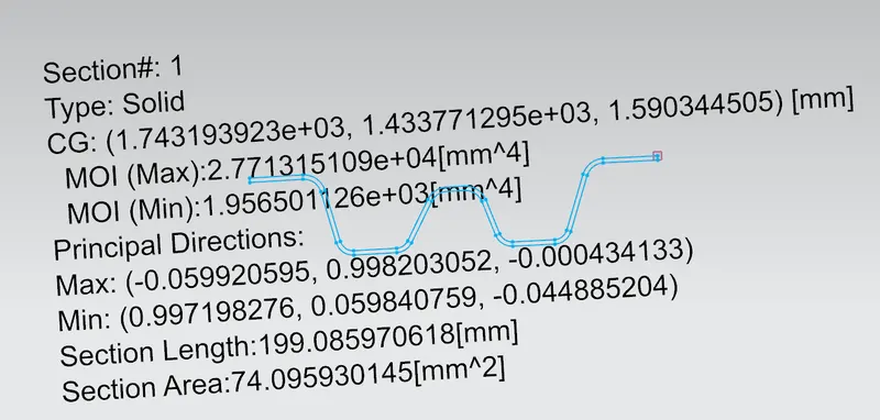
Value obtained as per design.
| ly | a | My | Ly | Lx | Y | s | Rx | Ry | t | Qr | Criteria |
| 1956.5 | 1.059286 | 862224 | 2037.04 | 1108.4 | 600 | 480.385 | 4370.37 | 2848.15 | 1.3 | 49.88014 | ok |
| 2489.5 | 1.212146 | 1036891 | 2037.04 | 1081.212 | 996.34 | 396.205 | 3781.2 | 6418.02 | 1.3 | 33.68603 | ok |
| 1968.59 | 1.015262 | 897230.1 | 2037.04 | 1063.744 | 1392.89 | 492.175 | 4210.76 | 10324.92 | 1.3 | 12.60473 | ok |
Judgment condition
Qr ≥ 3.1
FINAL FILES
https://drive.google.com/drive/folders/1P5bXBCSEX6yG1IYl7FarC5TfHQUhywkV?usp=sharing
above is the link provided for all the design files.
CONCLUSION
For the given roof styling, flanges and reinforcements are created also, and heat distortion criteria and snow load calculations are done.