Roof Design
OBJECTIVE :
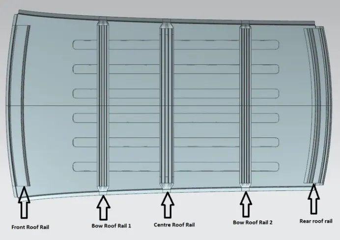
The objective of this project is to design car roof with essential flanges and reinforcements like ditch area , front roof rail , bow roofs, central roof rail and rear roof rail for the the given styling surface
Perform a curvature study on the roof and perform the calculations for the heat distortion and snow load criteria to determine whether the bow roofs are at the correct positions.
Finding moment of inertia and section modulus for Bow roofs , central roof rail . front roof rail and rear roof rail .
Perform the draft analysis for each reinforcements
SOFTWARE USED :
Design of any product starts from an requirement . The design engineer sketches the product based on the the requirement . Then the 2D sketch with the proper dimensions is converted into the 3D model using the advanced CAD software's . The another important thing in the design is that , every product that is designed should be able to manufacture
. so the role of the design engineer is to design the product that can be easily manufactured and with less cost effective . This is the place where the Design for manufacturing [DFM] and Design of assembly [DFA] takes a role while developing any
product . The process of development of design carries on until the design satisfies the customer needs .Here in this project the product that we are going to develop is a car roof
CAR ROOF :
An automobile roof or car top is the portion of an automobile that sits above the passenge compartment, protecting the vehicle occupants from sun, wind, rain, and other external elements. Roof is the structure above the wind shield glass having the reinforcements to provide the strength to the overall structure and to with stand the over head forces like snow
WHY REINFORCEMENTS :
If the roof is flat it is very weak and cannot able to with stand the forces like snow , so in order to increase the strength of the roof these reinforcements like front roof rail, central roof rail, rear roof rail and the bow roofs are introduced and joined to the flat surface of the roof with the different joining process
Different types of reinforcements that the car has are :
Front roof rail
Rear roof rail
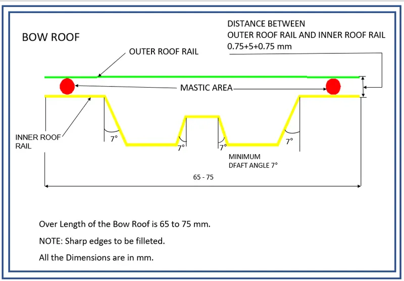
Bow roofs
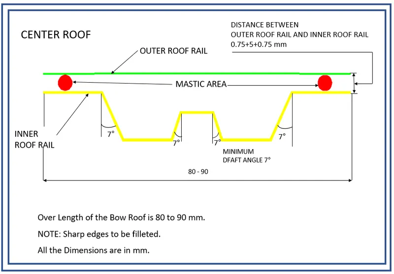
Central roof rail
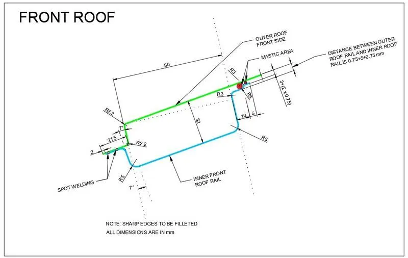
Front roof rail:
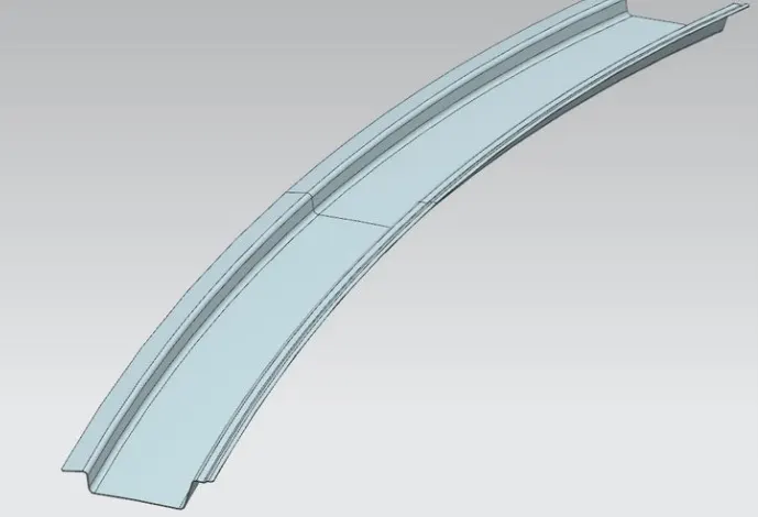
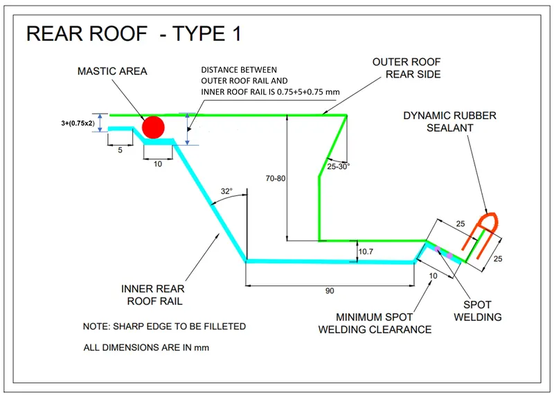
Rear roof rail:
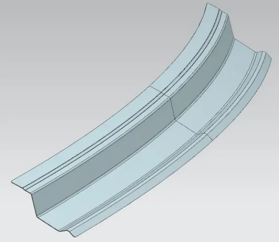
Bow roofs:
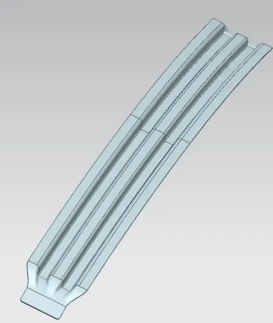

Central roof rail :
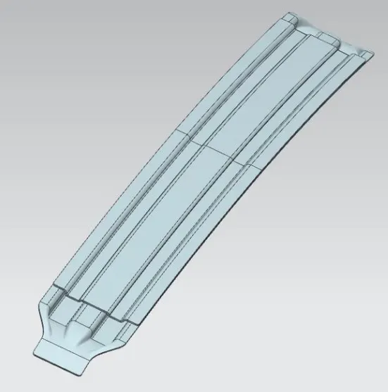
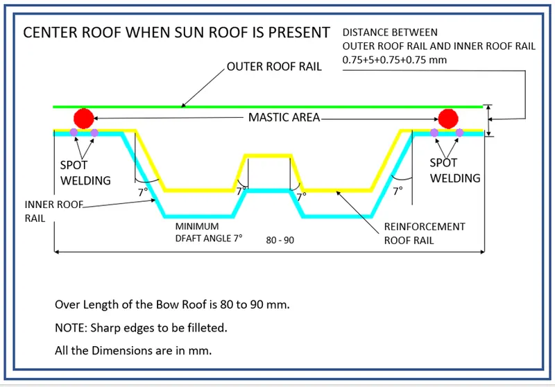

CALCULATIONS
Heat Distortion Curvature StudyThis study is used to find out and predict the heat distortion temperature at where the material starts to soften when exposed to a fixed load. So in order to avoid bending or damage of the roof based on this
calculation we will decide the position on the roof bows on the roof.
Bow–Roof Prediction Formula
W = [1.73 x 10^(-3) x L] + [1.85 x 10^(-8) x (R^2)/t] + [ 1.10x10^(-3) x l] - 2.68
Where,
L = Roof Length in X-Direction[mm](Roof dimension in 0-Y)
R = Roof curvature
R = 2(Rx*Ry)/(Rx+Ry)
Rx = X curvature
Ry = Y curvature
t = Roof plate thickness [mm]
l = Bow Roof Span [mm]
Result:
Bowposition Rx Ry R l L t R /2 W OK/NG
FR and1st 5626.39 3067.66 3970.5 448.56 2033.7 1.5 21019825.94 1.53 OK
1 andCTR 4854.3 6624.76 5602.99 365.81 2033.7 1.5 41858066.77 1.63 OK
CTR and 2nd 4065.16 10593.91 5875.67 463.2 2033.7 1.5 46031333.73 1.77 OK
2 and RR 3424.34 14478.23 5538.68 352.33 2033.7 1.5 40902692.46 1.6 OK
Snow Load Prediction Formula
Qr = [Iy x t2] / [α x s x [(Rx + Ry)/2]2 x 10-8]
Note: The Qr value given over here is correct. There was a typo error in the formula given in the video.
Where,
α = My x Lx2 x 10-12 , My = Y(Ly-Y)
t = Roof plate thickness [mm]
Ly = Distance between the front and rear roof Rails on the Vehicle along with 0Y[mm]
Length of Roof panel with the center point between Roof rail Front /Rear as the front and rear reference point.
Lx = Distance between the Left and Right end of the roof on the Roof BOW [mm]
The width of the roof panel is exposed on the surface.
Y = Distance front Front Roof Rail to Roof BOW[mm]
s = Distance for which Roof BOW bears divided load [mm]
s = L1/2 + L2/2
Iy = Geometrical moment of inertia of Roof BOW (Y cross-section )[mm4]
Rx = Lateral direction curvature radius of roof panel Y cross-section on Roof BOW [mm]
Roof panel curvature Radius of the Length Lx in Front view
Ry = Longitudinal Direction curvature radius of the Roof panel X cross-section on Roof BOW [mm]
Roof panel X curvature radius of length s in Side view
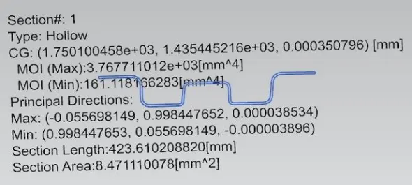
Bow roof:
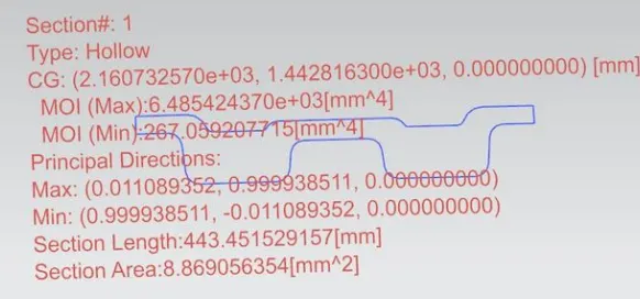
Centre bow roof:
Bow roof:
Result:
Bowposition Iy α Lx Ly Y S Rx Ry t Qr Determinat
FR and1st 161.19 1.05 1119.69 2033.7 569.65 447.74 4105.6 15113.26 1.5 0.84 NG
1 andCTR 267.05 1.21 1081.72 2033.7 979.65 464.47 3794.03 10543.14 1.5 2.09 NG
CTRand2nd 161.3 0.91 1059.39 2033.7 1488.08 447.71 4231.18 6602.02 1.5 3.03 NG
Draft analysis
Before we give the part for manufacturing we have to some analysis ourself to check all the constraints and to check if we have any negative draft on a part .
We have a tool called draft analysis in NX Cad to check the following.
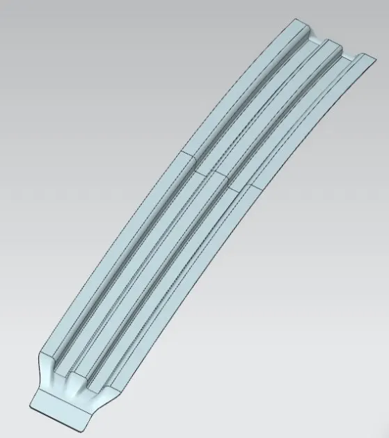
Front roof rail:

Bow roof 1:
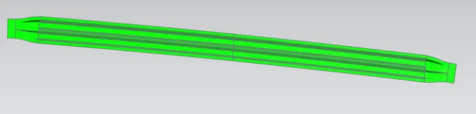
Centre roof rail:

Bow roof 2:

Rear roof rail:
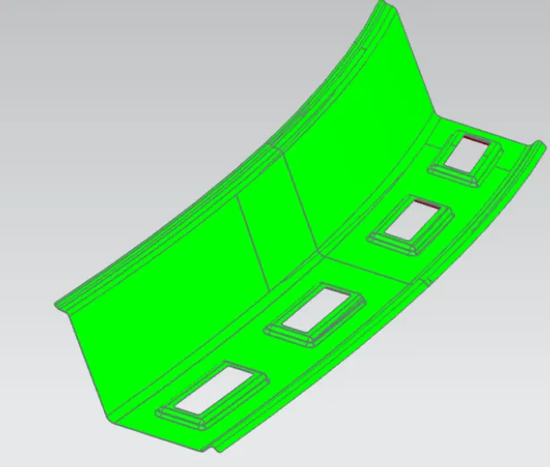
ROOF IMAGES:
TOP VIEW:
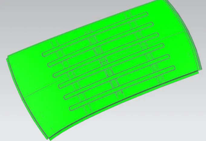
We gave a limit angle of 3 degree.
When the colour is green it means it has a positive draft it means area which are more than 3 degree i shown as green. If it is shwn in yellow that means it has less then 3 degrees and if in blue or red then means it has negative draft.
Section modulus:
Original
S =147.9884mm
Offsetting the bottom curve by 0.5mm downwards
S =165.1002mm
Offsetting the bottom curve by 0.5mm up
S =164.9576mm
From the above observations we can say that when we offset the curve 0.5mm downwards, we get a better section modulus.