Roof Design
ROOF DESIGN
The roof is a styling surface part which is fixed with the BIW body through the rails and panels inside the upper roof to provide it strength and stiffness. An automobile roof sits above the passenger compartment, protecting the vehicle occupants from sun, wind, rain, and other external elements.
The conventional task of the roof is to provide protection against hard local contact.In case of roll over,compartment integrity is provided by the compartment frames.
Design and Functional Requirements for the Roof :-
While designing the roof following aspects have to be taken into consideration.
- Visibility Criteria
- Head Room clearance
- Heat Distortion criteria
- snow load criteria
Design of the Roof :-
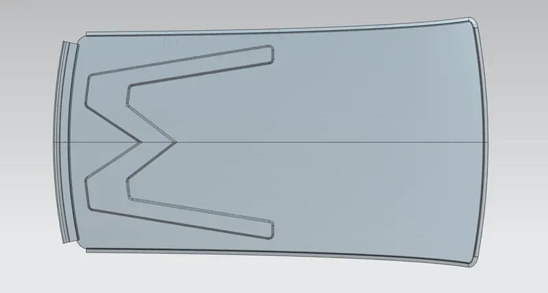
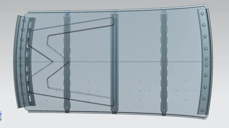
Top View :-
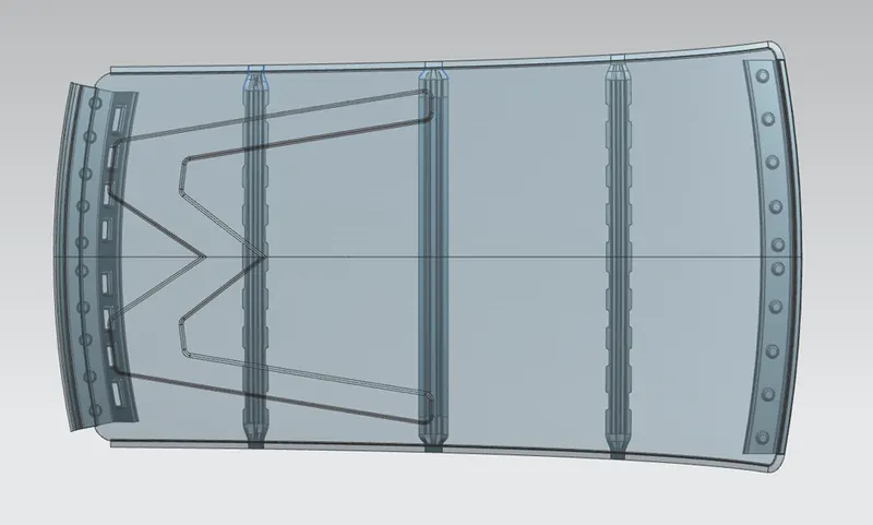
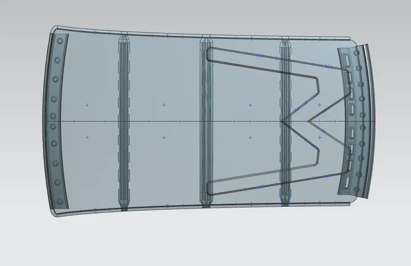
Bottom View:-
Roof Rails :-
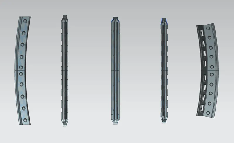
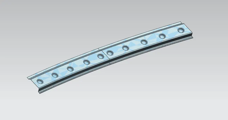
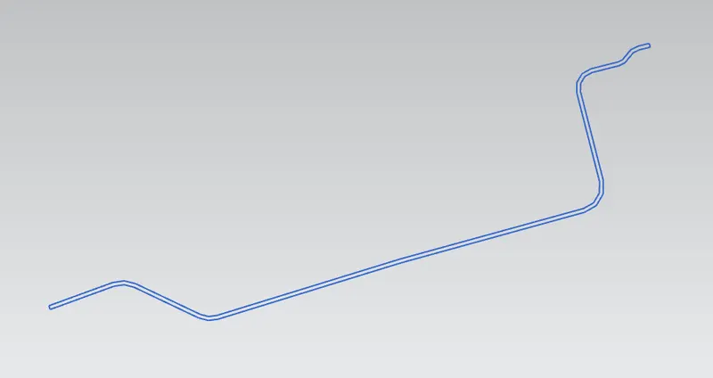
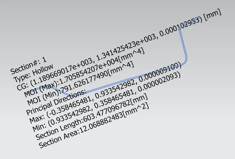
Front Roof Rail :-
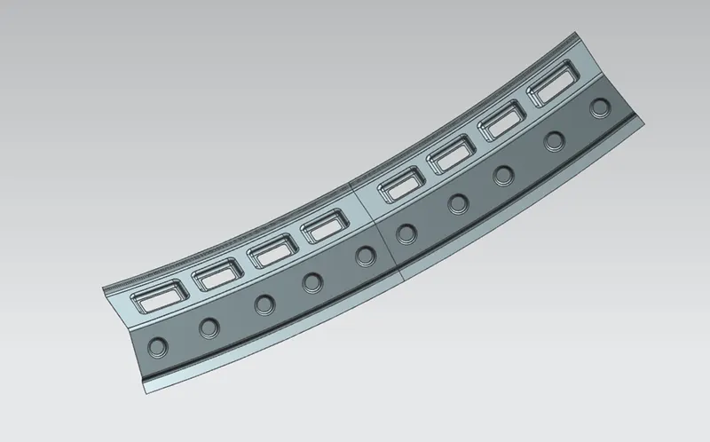
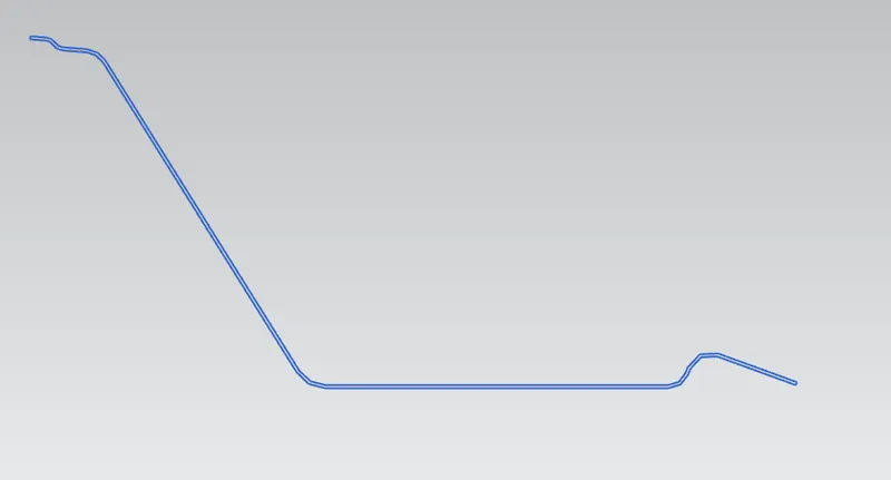
Rear Roof Rail :-
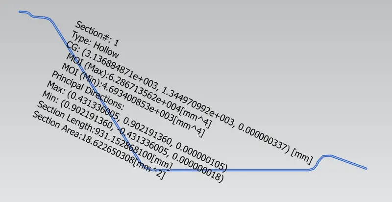
Bow Roof-1 :-
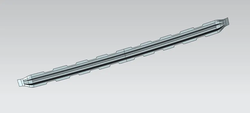

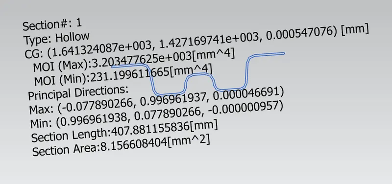
Bow Roof-2 :-
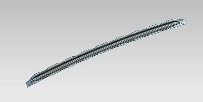
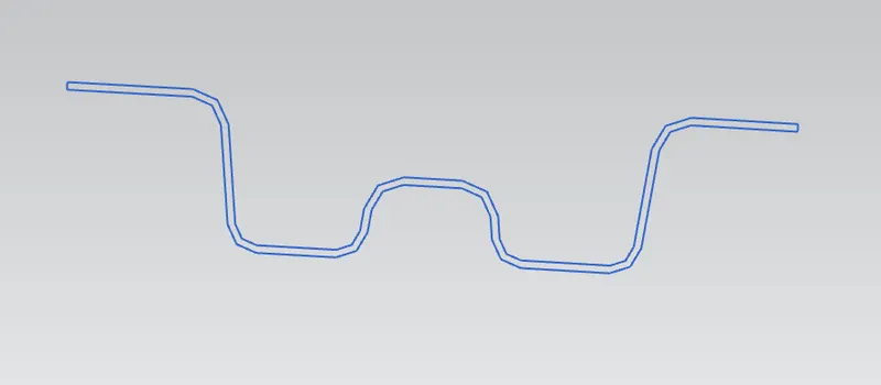
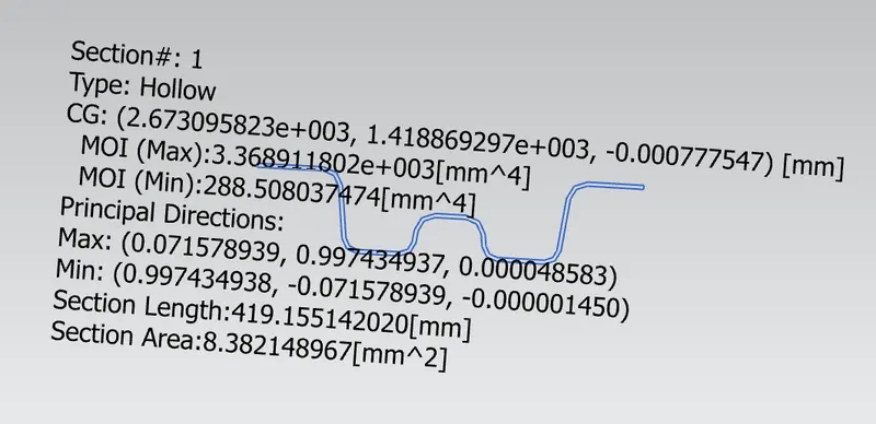
Center Roof Rail :-
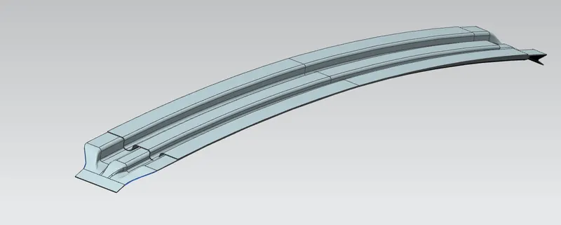
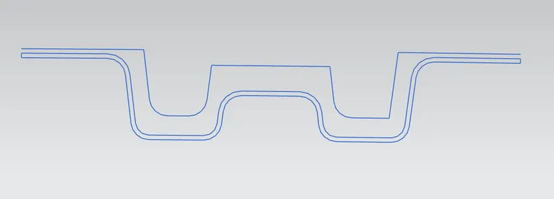
FORMULAS FOR CALCULATION
1.HEAT DISTORTION CRITERIA
W = [1.73 x 10^(-3) x L] + [1.85 x 10^(-8) x (R^2)/t] + [ 1.10x10^(-3) x l] - 2.68
L = Roof Length in X-Direction[mm](Roof dimension in 0-Y)
R = Roof curvature
R = 2(Rx*Ry)/(Rx+Ry)
Rx = X curvature
Ry = Y curvature
t = Roof plate thickness [mm]
l = Bow Roof Span [mm]
W must be - OK< 2.7> 3.1
| S.no | Bows | Rx | Ry | R | I | L | t | R^2/t | W | OK/NG |
| 1 | FR to 1st BR |
5781.56 |
2376.36 | 3368.27 | 370.62 | 2033.7 | 0.75 | 15126990 | 1.52 | OK |
| 2 | 1st BR to 2nd BR | 4949.86 | 6172.08 | 5493.77 | 449.65 | 2033.7 | 0.75 | 4024204 | -2.11 | OK |
| 3 | 2nd BR to CRR | 1476.82 | 10852.66 | 2603.37 | 428.57 | 2033.7 | 0.75 | 9036713 | -2.20 | OK |
| 4 | CRR to RRR | 806.85 | 14739.25 | 1523.94 | 344.86 | 2033.7 | 0.75 | 3120955 | -2.30 | OK |
Here the obtained results of W are satisfactory, the design can be forwarded for further process.
2.SNOW LOAD CRITERIA
Qr = [Iy x t2] / [α x s x [(Rx + Ry)/2]2 x 10-8]
α = My x Lx2 x 10-12
My = Y(Ly-Y)
t = Roof plate thickness [mm]
Ly = Distance between the front and rear roof Rails on the Vehicle along with 0Y[mm]
Length of Roof panel with the center point between Roof rail Front /Rear as the front and rear reference point.
Lx = Distance between the Left and Right end of the roof on the Roof BOW [mm]
Width of the roof panel exposed on the surface.
Y = Distance front Front Roof Rail to Roof BOW[mm]
s = Distance for which Roof BOW bears divided load [mm]
s = L1/2 + L2/2
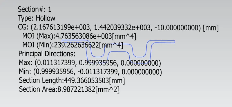
Iy = Geometrical moment of inertia of Roof BOW (Y cross-section )[mm4]
Rx = Lateral direction curvature radius of roof panel Y cross-section on Roof BOW [mm]
Roof panel curvature Radius of the Length Lx in Front view
Ry = Longitudinal Direction curvature radius of the Roof panel X cross-section on Roof BOW [mm]
Roof panel X curvature radius of length s in Side view.
Qr ≥ 3.1
250 ≤ s ≤ 380
| S.no | Bows | Iy | α | Lx | Ly | Y | S | Rx | Ry | t | Qr | OK/NG |
| 1 | FR to 1st BR | 231.19 | 0.9256 | 1134 | 2033 | 456.32 | 490.81 | 7233.68 | 2441.85 | 0.75 | 1.22 | NG |
| 2 | 1st BR to 2nd BR | 288.50 | 0.8466 | 1033 | 2033 | 525.30 | 515.43 | 5152 | 6069.52 | 0.75 | 1.83 | NG |
| 3 | 2nd BR to CRR | 239.26 | 0.8252 | 1033 | 2033 | 505.57 | 662.19 | 6140 | 6213.14 | 0.75 | 0.64 | NG |
Here the result of Qr is not satisfactory, we can make some changes in the Rx & Ry values on a trial and error method until we find the desired outcome, after which the model can be forwarded over to the styling team to change the curvature to improve the strength. Emboses are also provided on the styling susface in order to improve the strength.
Draft Analysis:-
The draft analysis technique is used to analyze whether our part/model created is manufacturable based on the draft condition applied. Here the part should get easily removed from the panel dies (in case of Sheet metal part) or Mold (in case of plastic)
The Designed roof was analysed for draft analysis, which provided the following results.
The provided positive draft limit angle is 5 deg
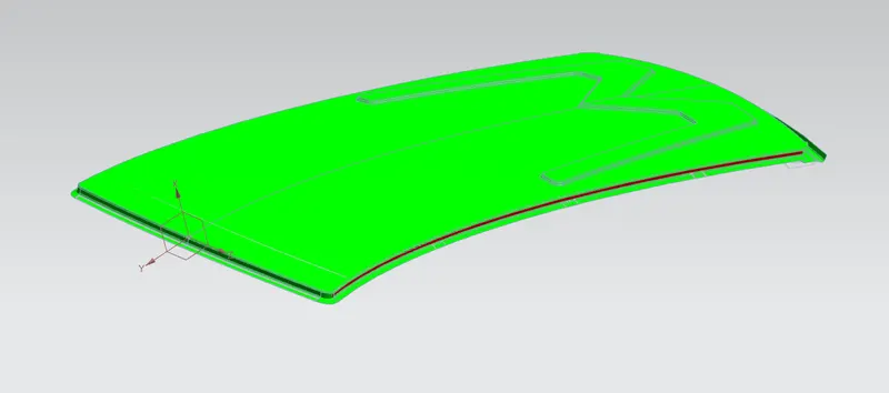
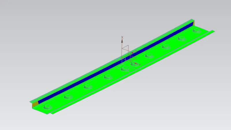
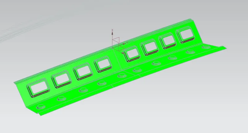
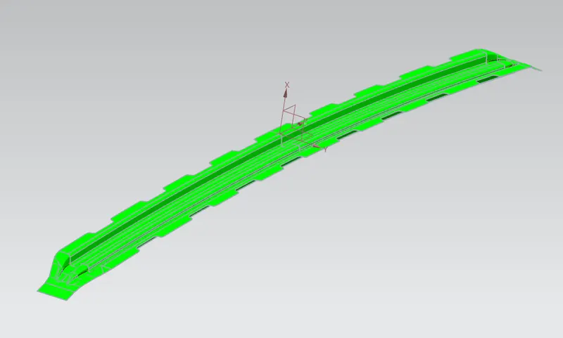
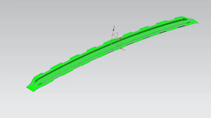
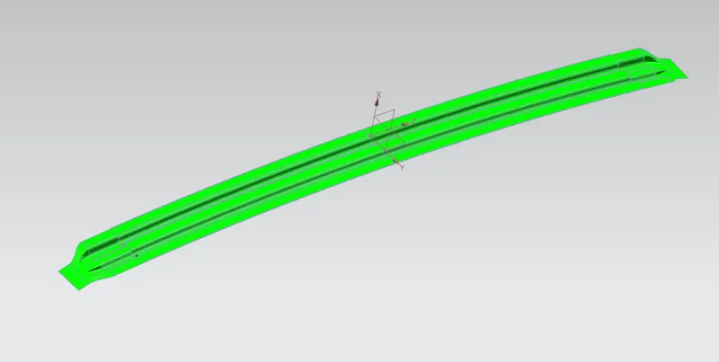
There are negative drafts identified,for which we can change the tooling angle for better results.