Roof Design
To Create an assembly by developing the essential flanges for the outer roof and creating the reinforcements.
Roof:
An automobile roof or car top is the portion of an automobile that sits above the passenger compartment, protecting the vehicle occupants from sun, wind, rain, and other external elements.
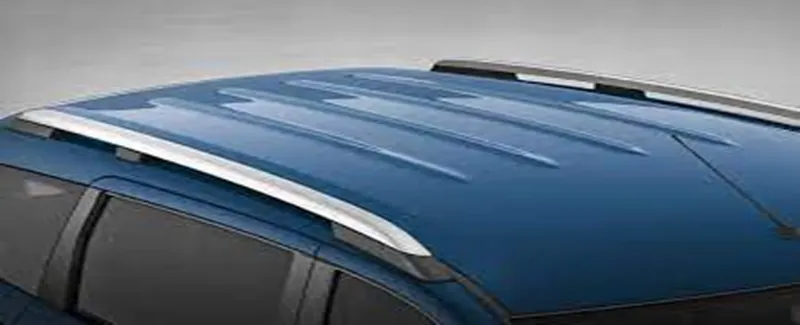
The roof is a styling surface part fixed with the BIW body through the rails and panels inside the upper roof to provide strength and stiffness.
The ditch area plays an important role in fixing the component's reinforcement.
The rails and reinforcements are joined to the ditch area with a spot weld where it's not the styling part.
The required tool opening angle is a minimum of 3 Degrees.
Factors which is considered before creating a Ditch area,
- Headroom clearance
- Visibility criteria
- Back door assembly
- Windshield assembly
INPUT:
Class A Surface
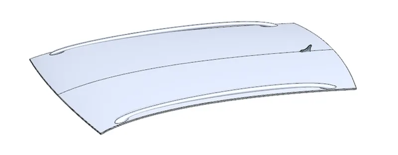
Components of roof:
- Front roof rail
- Rear roof rail
- Bow roof
- Centre roof rail
- Ditch area
Master section:
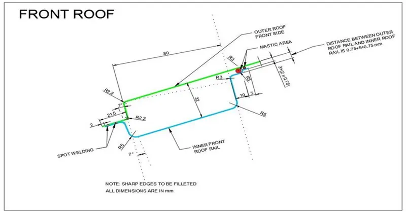
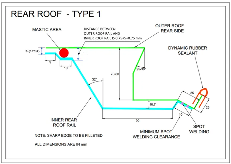
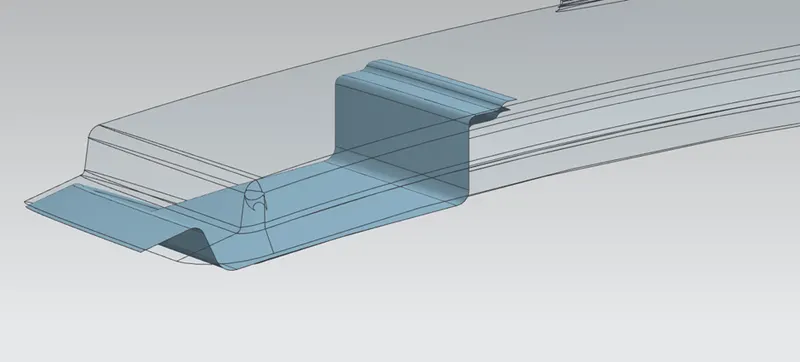
Front Roof Rail:
The front roof rail is used to provide strength to the roof panel front and it also acts as a link between windshield glass, roof panel, and headliner. Spot welds are applied at the windshield end of the rail and the other end is joined with the roof using mastic sealant which also increases the strength.
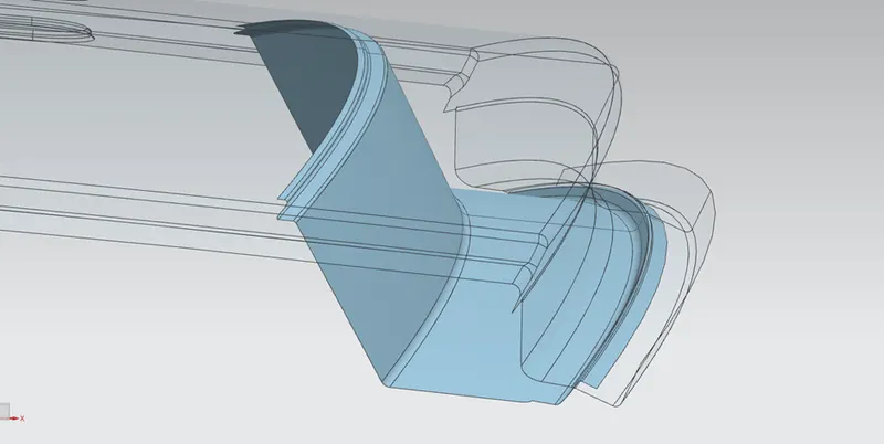
Rear Roof Rail:
The rear roof rail is again used to strengthen the roof and it acts as a link between the back glass and the roof which is connected to the backdoor of the car. Spot welds are applied at the back door end of the rail and the other end is joined with the roof using mastic sealant.
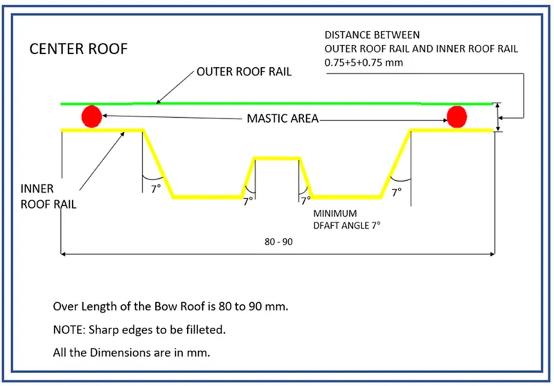
Centre Roof Rail:
The Centre roof rail will be at the centre of the roof to provide strength and stability to the roof. Here the centre roof rail is joined with the roof through mastic sealant.
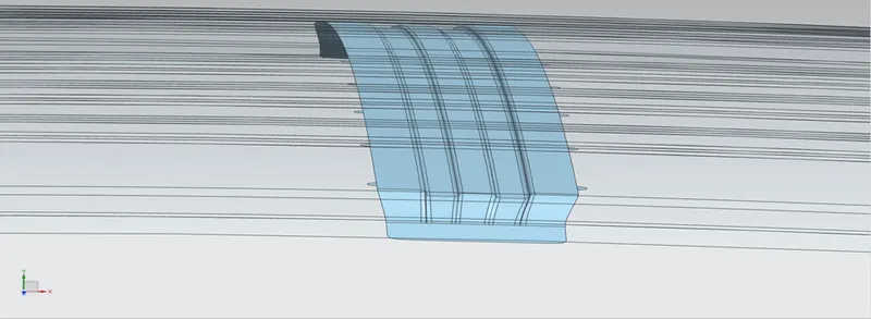
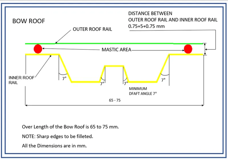
Bow roof:
The bow roof is used for strengthening purposes and attached to the upper roof surface with mastic sealants.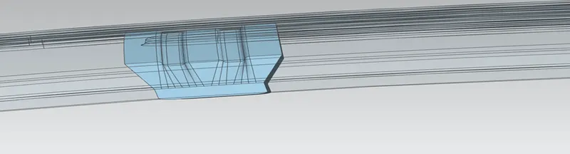
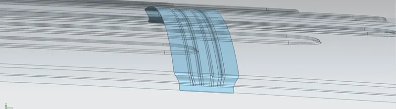
Ditch area:
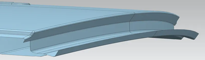
The Ditch area is an extended portion of the main roof canceled by other BIW panels’ rails support of the roof is attached to the ditch area using spot weld.
Roof Bow Calculations:
Heat Distortion Calculation:
W = [1.73 x 10^(-3) x L] + [1.85 x 10^(-8) x (R^2)/t] + [ 1.10x10^(-3) x l] - 2.68
Judgement Condition: OK< 2.7> 3.1
Where
L = Roof Length in X-Direction[mm](Roof dimension in 0-Y)
R = Roof curvature
R = 2(Rx*Ry)/(Rx+Ry)
Rx = X curvature
Ry = Y curvature
t = Roof plate thickness [mm]
l = Bow Roof Span [mm]
Except for Rx and Ry, all values can be measured on the model.
To get the Rx and Ry curvature a sketch was required-
- A sketch was created on a plane on top of the Roof
- The 0-Y line was created in the X-Direction in the center of the roof
- Then a Horizontal line below 300mm was created named as -3Y Line
- Two lines on both sides at 100mm were created from -3Y Line
- An intersection point on line was created and projected on the outer Panel of the Roof
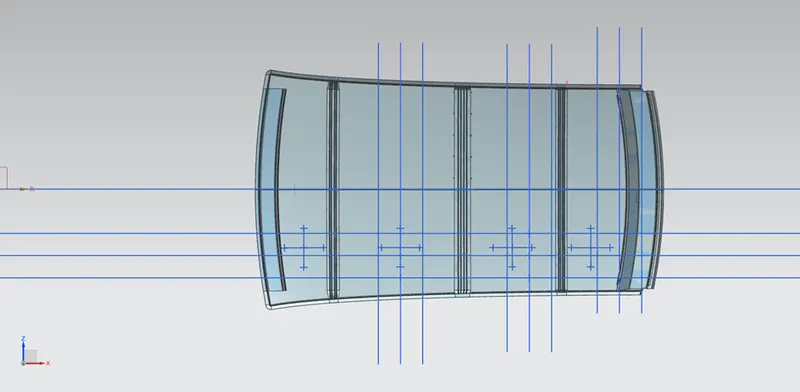
By using all Values Heat Distortion was Calculated in MS Excel:

According to Judgement Condition: OK< 2.7> 3.1
All Values are under Judgement Condition.
Section Modulus:
Section modulus is a geometric property for a given cross-section used in the design of beams. Other geometric properties used in the design include an area for tension, radius of gyration for compression, and moment of inertia for stiffness. The Section modulus is defined as
S=Iy
Where,
S = Section Modulus
I = Moment of Inertia
y = Distance from the neutral axis to any given part.
Front Roof rail:
The intersection was created and then Section Inertia command was used to obtain MOI
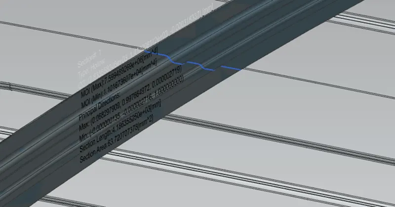
S=I/Y
S=
I=7.5994mm4
Y=126.876/2=63.438
S=12.11mm3
Center Roof rail: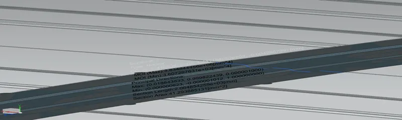
S=I/Y
S=
I=3.8943mm4
Y=119.873/2=59.936
S=7.954mm3
Rear Bow roof: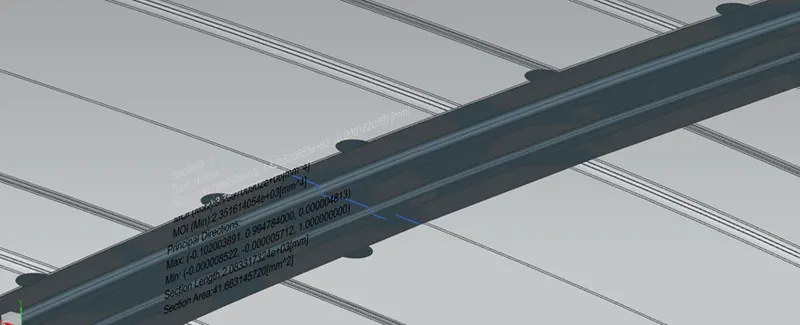
S=I/Y
S=
I=3.7573mm4
Y=39.956/2=19.977
S=1.939mm3
Draft Analysis:
Draft analysis was performed with 7 Degrees Value (generally given in sheet metal)
Front Roof rail: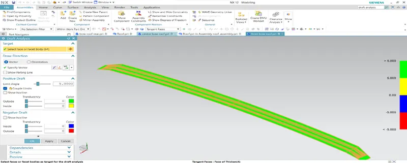
Center Roof rail: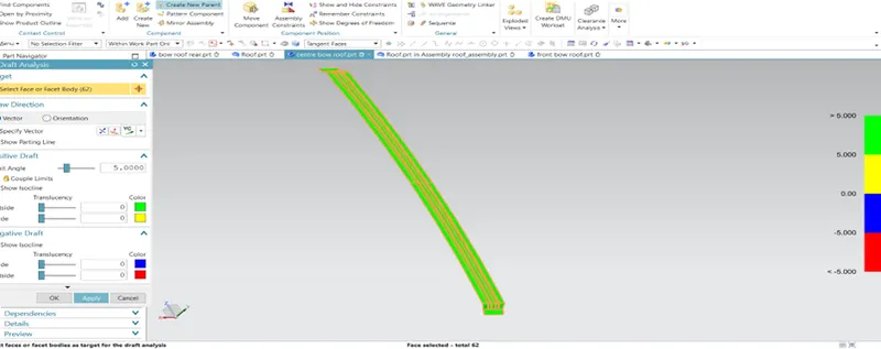
Rear Roof: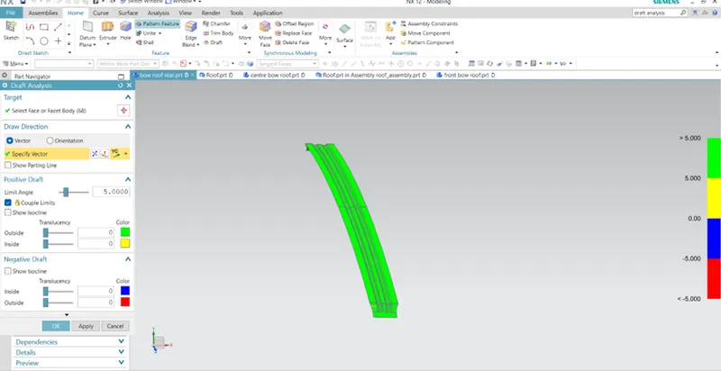
Outer panel: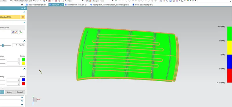
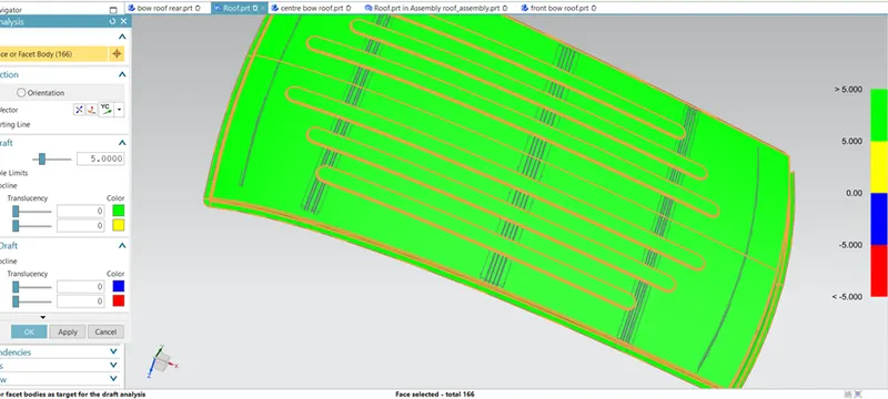
Front view: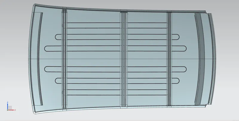
Side view: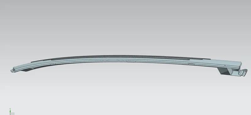
Top view: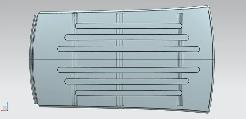
Back view: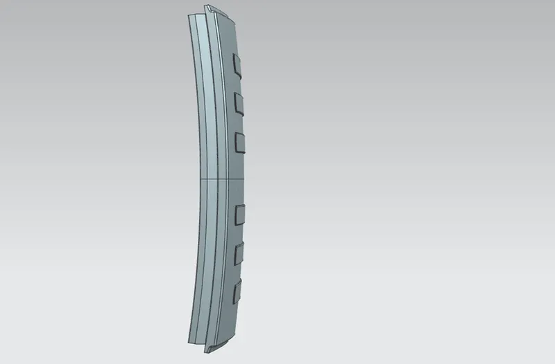
Conclusion:
The Roof was created in Siemens NX Student Version with all the required parameters and different Calculations were done for safety concerns.