Roof Design
ROOF:
- An automobile roof or car top is the position of an automobile that sits above the passenger’s compartment, protecting the vehicle occupants from sun, wind, rain, and other external elements.
- Roof is the structure above the wind shield glass having the reinforcements to provide the strength to the overall structure.
- Because the earliest automobiles were designed in an era of horse-drawn carriages, early automobile roofs used similar materials and design
Roof is designed by following some criteria:
- Visibility criteria as safety and functionality
- Head clearance for ease and comfort
- Draft analysis fro easy manufacturing and tooling
- Safety parameters for users
- Heat distortion
- snow load criteria
- Curvature study
Car roof types:
- Hard top
- Sun roof
- T-top
- Targa top
- Vinyl’s top
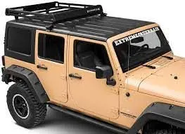
1.Hardtop
- Hardtop is a rigid form of automobile roof, which for modern cars is typically constructed from metal.
- A hardtop roof can be either fixed (i.e. not removable), detachable for separate storing or retractable within the vehicle itself.
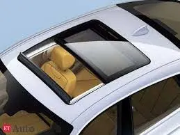
2.Sunroof
- Sunroof is a movable panel that opens to uncover a window in an automobile roof, allowing light and fresh air to enter the passenger compartment.
- Sunroofs can be manually operated or motor driven, and are available in many shapes, sizes and styles.
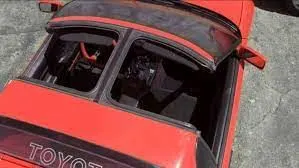
3.T top
- T-top is an automobile roof with a removable panel on each side of a rigid bar running from the center of one structural bar between pillars to the center of the next structural bar.
- The panels of a traditional T-top are usually made of auto grade safety glass.
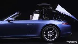
4.Targa top
- Targa top, or targa for short, is a semi-convertible car body style with a removable roof section and a full width roll bar behind the seats.
- The rear window is normally fixed, but on some targa models, it is a removable plastic foldable window, making it a convertible-type vehicle.
5.Vinyls
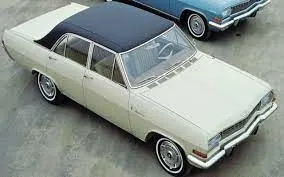
- Vinyl roof refers to a vinyl covering for an automobile's top.
- This covering was originally designed to give the appearance of a convertible to models with a fixed roof and eventually evolved into a styling statement in its own right.
PROCEDURE:
Class –A surface:
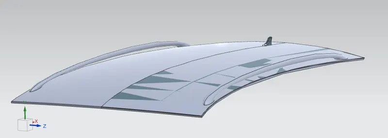
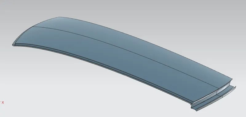
- After the file is opened, the roof part is not joined together but as the individual surfaces.
- It is also seen as the surface is perfectly symmetrical in shape which helps us to work on the half of the portion and reflect it which creates the whole roof
Creating the Flanges for the Roof:
- Extract the upper roof part by selecting it.
- Now select an edge and sweep it with the 7 degree draft with a length of 20mm.
- From the edge of the sweep take another sweep with the 7 degree draft of length 21.5 mm.
- Follow the same procedure with the other edges.
- Now, create the curved edges by using curves as the guide curves and the multi section surface option.
- Join the Surfaces together and give the fillets.
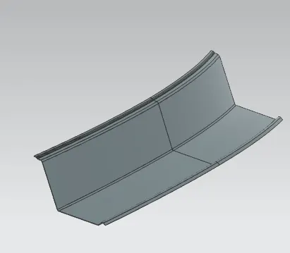
Creating the Front roof Rail:
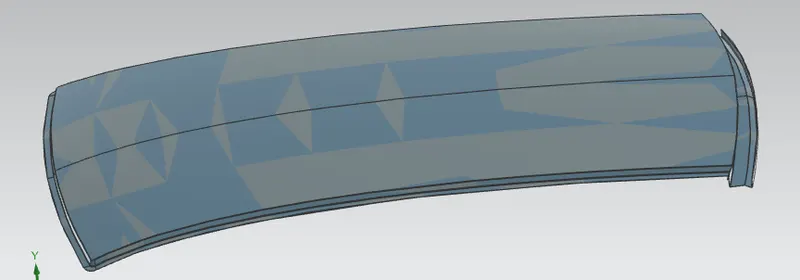
- Offset the roof to 6.5mm and split it with a distance of 5mm.
- Similarly, create an offset of 4.5mm and cut it.
- Now create a base offset of 32mm from the roof.
- Create the respective sweeps for these offsets and trim them together.
- Give the Edge fillets to it
creating rear roof:
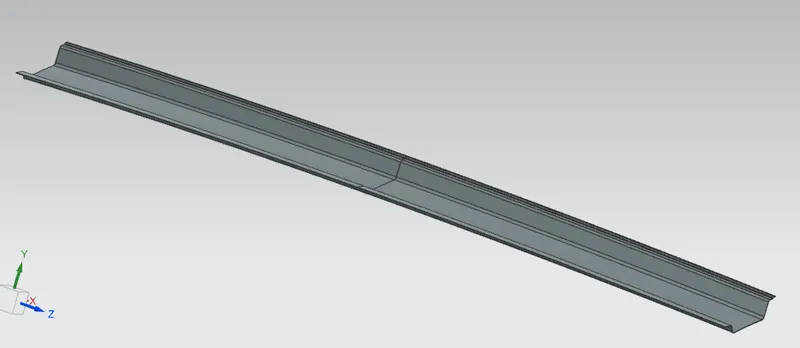
- The rear roof rail follows a similar procedure as the front roof and the values for it are given in the diagram.
- Make sure that the Rear roof has a positive draft angle.
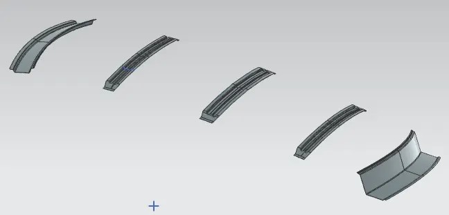
Creating the center roof rail:
- It is attached at the center yet below the roof.
- To create the center roof as per the diagram, we use the offset and select the parallel curve option and give an offset value on sides and create a cut on the offset.
- Now create the part as per the design standards and make sure that the offset is given considering the thickness of the component.

Creating the Bow roofs:
- There are 2 bow roofs that are created to give strength to the roof.
- Follow the same method as with the center reinforcement to create the bow roof.
- Now, after the bow roof is created. The mastic points need to be created.
- Use the parallel curve and connect the outer edge and parallel curve to cut the elements.
- Once created use the split option to create the mastic points.


Creating a Solid:
- After Creating the surfaces, use the thicken option to create the solids with the proper thickness.
- The thickness for the Roof and front roof rail is 0.75mm, for the rear roof rail is 0.75mm, for the center roof thickness is 0.75mm, and for the bow roof, it is 0.75mm.
Calculation:
- In the assembly we’re going to calculate heat distortion criteria and snow load criteria.
- Heat distribution criteria is the calculation of how the roof will stand the heat capacity.
- And also measure the draft analysis after roof assembly.
- In snow load criteria we’re going to calculate snow load with stand capacity of roof.
- In the foreign countries in the rainy season there is a snowfall in that kind of situation roof must withstand the snow load that is why we calculate this
Heat Distortion Criteria:
- Predicting heat distortion for the roof is important since it is exposed to the heat for a long time and high temperature will affect the roof structure if the designing does not confirm with the heat distortion criteria.
- The study helps to determine the position of roof to provide strength to the route to avoid bending and deflection of the roof due to heat.
- Bow curvature study you see following formula will help best check whether the boardroom potion important required strength of roof.
Heat Distortion Criteria:
W = [1.73 x 10^(-3) x L] + [1.85 x 10^(-8) x (R^2)/t] + [ 1.10x10^(-3) x l] - 2.68
Judgement Condition : OK< 2.7> 3.1
Where
L = Roof Length in X-Direction[mm](Roof dimension in 0-Y)
R = Roof curvature
R = 2(Rx*Ry)/(Rx+Ry)
Rx = X curvature
Ry = Y curvature
t = Roof plate thickness [mm]
l = Bow Roof Span [mm]
|
S.no |
Bow’s |
Rx |
Ry |
R |
L |
L |
t |
w |
OK |
remark |
|
1. |
FR&1st |
2535.637 |
5738.237 |
3517.11 |
2029 |
408.371 |
0.75 |
1.5 |
Ok<2.7 |
Pass |
|
2. |
1st & Cntr |
6508.743 |
4893.768 |
2793.44 |
2029 |
440.267 |
0.75 |
1.5 |
Ok<2.7 |
Pass |
|
3. |
Cntr&2nd |
10881.326 |
3918.037 |
5761.524 |
2029 |
425.318 |
0.75 |
2.1 |
Ok<2.7 |
Pass |
|
4. |
2nd& RR |
14907.165 |
3231.113 |
5311.059 |
2029 |
302.685 |
0.75 |
1.8 |
Ok<2.7 |
Pass |
From the above table it can be concluded that all values of W< 2.7 and also not W>3.1 so thus infers that current positioning of Bow roof are good in state as per design and found OK.
Snow Load criteria:
Snow load criteria study is done to check the durability of the roof to withstand snowfall and reflex back to its original shape without any permanent deformation once the load is removed.
Snow load Prediction formula
Qr = [Iy x t2] / [α x s x [(Rx + Ry)/2]2 x 10-8]
Judgement condition = Qr ≥ 3.1
250 ≤ s ≤ 380
Where
α = My x Lx2 x 10-12 , My = Y(Ly-Y)
t = Roof plate thickness [mm]
Ly = Distance between the front and rear roof Rails on the Vehicle along with 0Y[mm]
Length of Roof panel with the center point between Roof rail Front /Rear as the reference point of the front and the rear.
Lx = Distance between the Left and Right end of the roof on the Roof BOW [mm]
Width of the roof panel exposed on the surface.
Y = Distance front Front Roof Rail to Roof BOW[mm]
s = Distance for which Roof BOW bears divided load [mm]
s = L1/2 + L2/2
Iy = Geometrical moment of inertia of Roof BOW (Y cross-section )[mm4]
Rx = Lateral direction curvature radius of roof panel Y cross-section on Roof BOW [mm]
Roof panel curvature Radius of the Length Lx in Front view
Ry = Longitudinal Direction curvature radius of the Roof panel X cross-section on Roof BOW [mm]
Roof panel X curvature radius of length s in Side view
| S.No | BOW | Iy | α | Lx | Ly | y | S | Rx | Ry | t | Qr">Qr | OK |
| 1 | FR&1st | 168.77 | 0.99 | 1137.63 | 2029.06 | 501.3 | 509.4 | 781.19 | 711.24 | 0.75 | 36.84 | OK |
| 2 | 1st & Cntr | 393.39 | 1.20 | 1083.95 | 2029.06 | 1018.9 | 510.1 | 375.19 | 374.85 | 0.75 | 25.7 | OK |
| 3 | Cntr&2nd | 346.53 | 0.86 | 1056.73 | 2029.06 | 1521.66 | 463.6 | 727.00 | 726.07 | 0.75 | 92.6 | ok |
| 4 | 2nd& RR | 0.17 | 1043.02 | 2029.06 | 1946.23 | - | 715.08 | 712.70 | 0.75 | - | - |
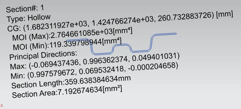
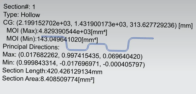
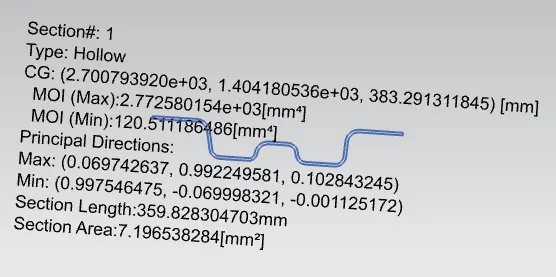
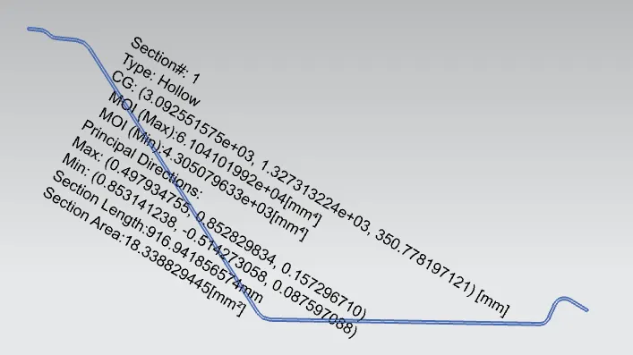
SECTION MODULUS:
- Section modulus is a geometric property for a given cross-section used in the design of beams or flexural members.
- Other geometric properties used in the design include an area for tension and shear, the radius of gyration for compression, and moment of inertia, and polar moment of inertia for stiffness.
- Any relationship between these properties is highly dependent on the shape in question.
calculate the section modulus using the formula S = I/y
There are two types of section moduli, the elastic section modulus, and the plastic section modulus.
For general design, the elastic section modulus is used, applying up to the yield point for most metals and other common materials. The elastic section modulus is defined as S = I / y
The plastic section modulus is used for materials where elastic yielding is acceptable and plastic behavior is assumed to be an acceptable limit. Designs generally strive to ultimately remain below the plastic limit to avoid permanent deformations, often comparing the plastic capacity against amplified forces or stresses.
MOMENT OF INERTIA:
The moment of inertia is defined as the quantity expressed by the body resisting angular acceleration which is the sum of the product of the mass of every particle with its square of a distance from the axis of rotation. The moment of inertia is also known as the angular mass or rotational inertia.
FRONT ROOF RAIL
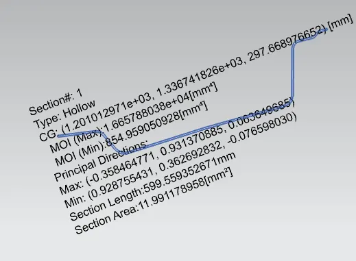
BOW ROOF 1
CENTER ROOF
BOW ROOF 2
REAR ROOF RAIL
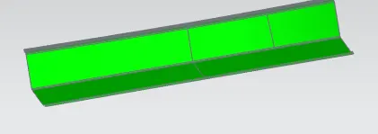
DRAFT ANALYSIS
Draft analysis is performed to check whether the part can be ejected from the tool so that it is manufacturable. Here I provide a min draft angle of 7 deg for all parts.
ROOF OUTER
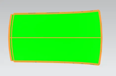
FRONT ROOF RAIL
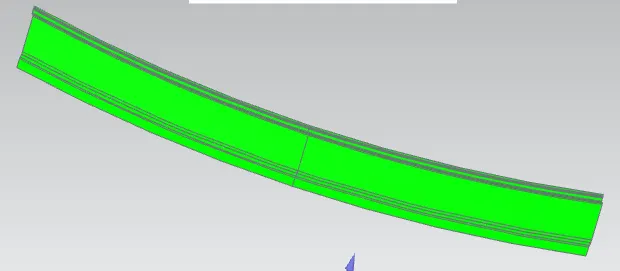
BOW ROOF 1

CENTER ROOF RAIL

BOW ROOF 2
REAR ROOF RAIL
CONCLUSION:
- Thus the roof outer panel and its reinforcement rails were designed using NX CAD . At first with the given roof styling surface , I developed the outer panel with essential flanges on the ditch area, reinforcement such as front roof rail, two bow roofs, center roof rail with an inner bow roof and rear roof rail with appropriate dimensions. Then checked the draft analysis and found the section inertia in OY section and also did a curvature study and necessary calculations