Roof Design
AUTOMOTIVE SHEETMETAL ROOF DESIGN USING NX CAD
OBJECTIVE/PURPOSE:
1.Main objective of the project is to create the Roof Sheetmetal design in NX cad, and also designing Front roof rail, rear roof rail, bow roof front, bow roof rear, centre roof rail and Reinforcement are creating to build the strong roof.
2. To Do a curvature study on Roof and performance calculations for Heat distortion and Snow load criteria to determine the position of the Bow roofs.
3.To Find the moment of inertia and section modulus for Bow-roofs and centre roof rail.
4.And, To Find the Draft Analysis of each part Using NX Cad.
SOFTWARE USED: NX 12.0
- To design the Sheetmetal ROOF in NX by using some Surfacing features.
- NX Cad software is vastlyused automotive, aerospace, thermal power station. Because of it is having modelling, drafting and manufacturing platform.
DESIGN METHODOLOGY:
I thought Simple design would be better Instead of SunRoofs Design I have followed below steps:
MASTER SECTION
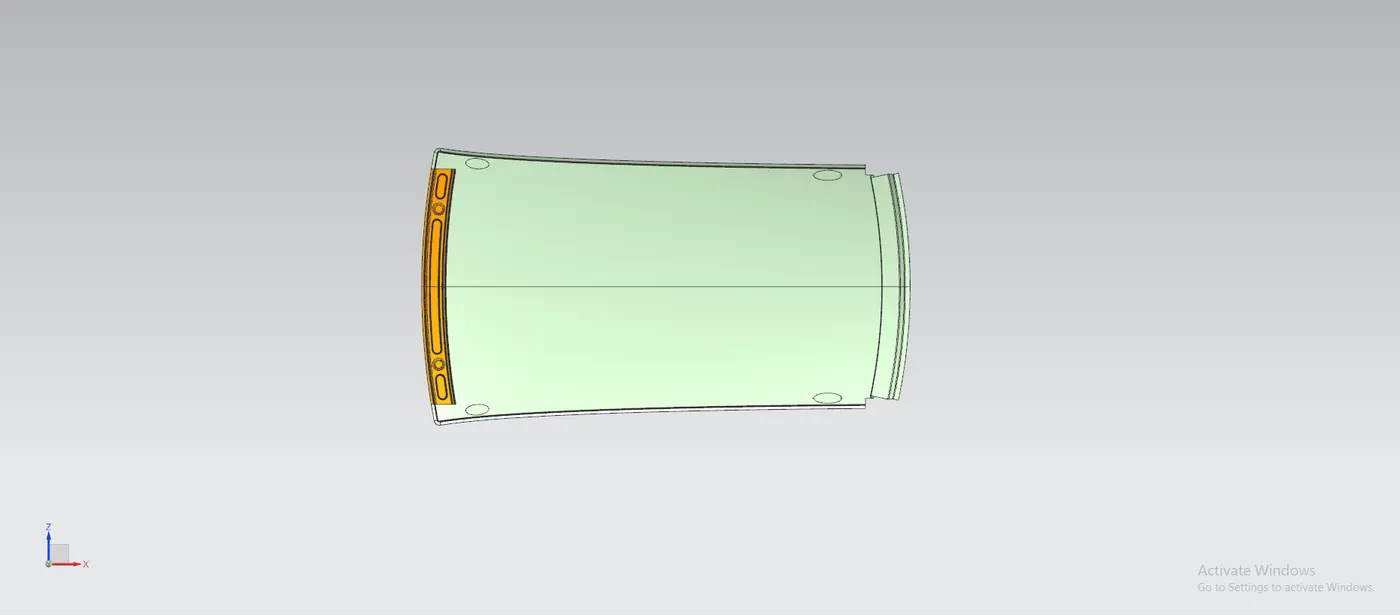
Front Roof Rail
Rear Roof Rail
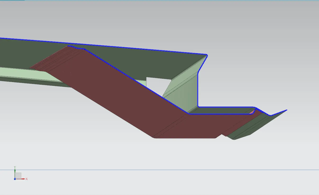
Center Roof Rail
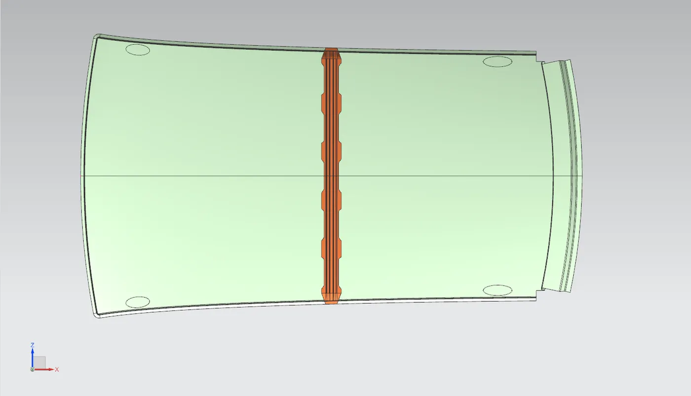
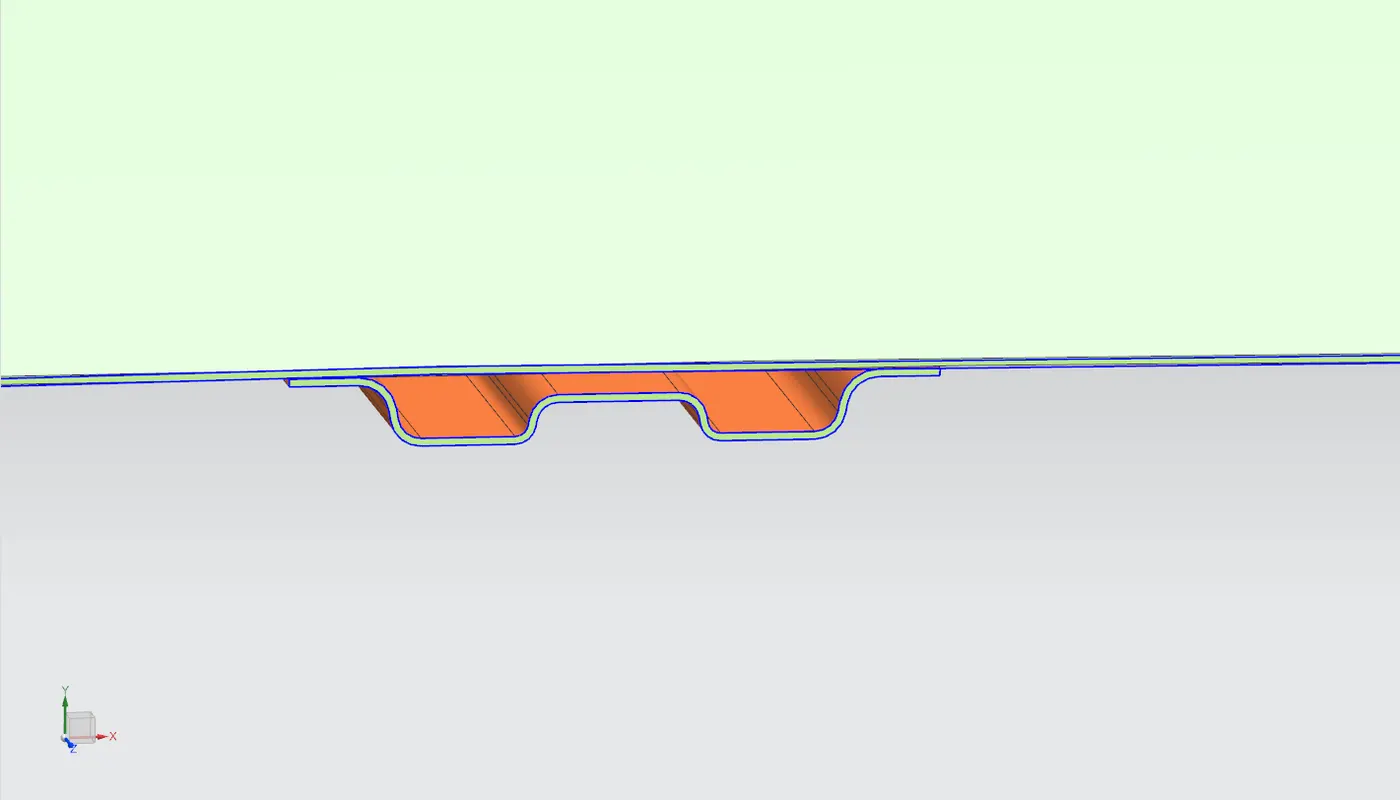
Bow Roof Rail
DESIGNING THE REINFORCEMENTS
ROOF – DITCH AREA
- The Ditch Area of the Roof was designed by taking the considerations provided by the styling team.
- The ditch area is designed to have only 3 degree of maximum draft angle and 0.75mm thickness.
- The ditch area is the extended portion of the main roof concealed by other BIW panels.
- The rails of the roof were attached by using Spot welds and Mastic Sealants.
- 1.Visibility Criteria 2.Head Room Clearance 3.Windshield clearance and 4.back door clearance was also taken into the design consideration of the Roof.
FRONT ROOF RAIL
- The front roof rail is joined with the wind shield, Body Side Inner and Outer panel, so the front roof has to be designed to have the visibility clearance for the Wind Shield.
- By considering the Deep Drawing of the part the front roof was designed to have the draft value of more than 5 degree.
- The front roof rail is having the same offset surface for the ditch area where both will be connected using Spot Welds.
- The front roof rail is provided with embosses to increase the strength and stiffness of the rail.
BOW ROOF RAILS:
- All the bow roof rails were placed between the front and rear roof rails.
- Bow roof rails were added to increase the stiffness of the roof since it has the large flat surface.
- To increase the curvature result of the roof where it needs to withstand the heat distortion and snow load criteria the bow roofs were positioned as per the standards.
- The bow roofs were provided with mastic points since the joining process will be done using the mastic sealants.
- Spot welds also possible but it will damage the aesthetic appearance of the car roof.
- Embosses were also provided all over the bow roofs to increase the stiffness rapidly.
- The bow roof position needs to satisfy the head room clearance and draft analysis for Deep Drawing.
Bow Roof Rail 1
Bow Roof Rail 2
CENTER ROOF RAIL
- Center roof rail was place after the Bow Roof 1 in my model but it can also be swapped between the Bow Roofs but it should be positioned as center of the roof as much as possible.
- The center roof rail was designed to have a reinforcement roof rail which helps the roof of a car to increase the efficiency in curvature study.
- For creating the Mastic Points and Embosses on the Center Roof Rail again the Head room clearance must be taken into account.
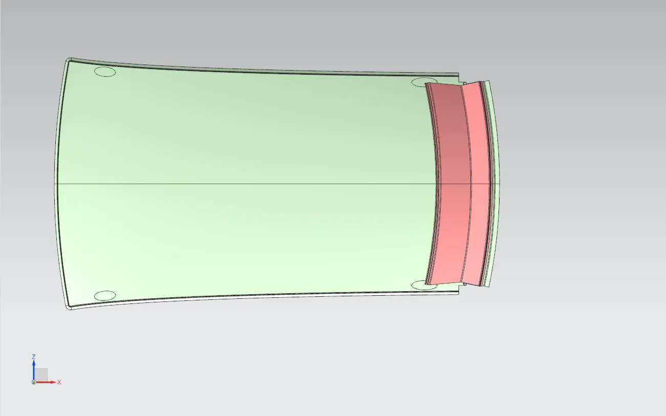
REAR ROOF RAIL
- The Rear Roof Rail was designed by taking the back door clearance into consideration since the opening and closing of the back door will effect on the roof.
- The ditch area on the roof was connected with the rear roof by using the mastic sealant or spot welding.
- Spot welding will be used for joining the hinges of the Back Door with the Roof.
- Embosses were added to increase the stiffness and strength of the rail without affecting the head room clearance.
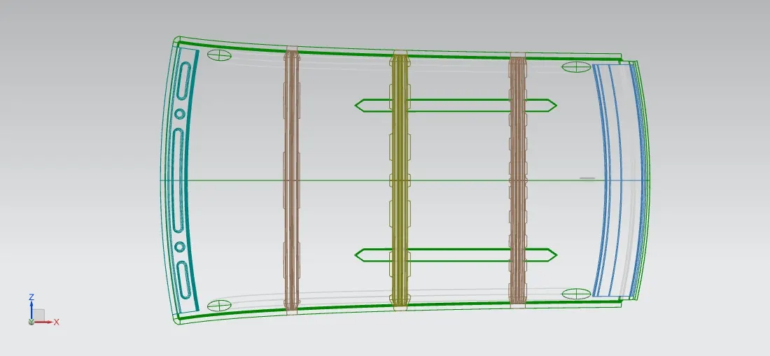
POSITIONs OF THE ROOF RAILS
- FR - FRONT ROOF RAIL
- BR1 - BOW ROOF RAIL
- CR - CENTER ROOF RAIL
- BR2 - BOW ROOF RAIL
- RR - REAR ROOF RAIL
ANALYSIS
Three types of analysis is carried out to get a successful design of the BIW roof of a car which satisfies the Manufacturing Standards.
1.DRAFT ANALYSIS
The Draft Analysis is a command which enables you to detect if the part you drafted will be easily removed. This analysis is performed based on color ranges identifying zones on the analyzed element where the deviation from the draft direction at any point, corresponds to specified values. it helps to know if the part is easily manufacturable or not
Outer Roof with Ditch Area
Front Roof Rail
Bow Roof Rail – 1
Center Roof Rail
Bow Roof Rail – 2
Rear Roof Rail
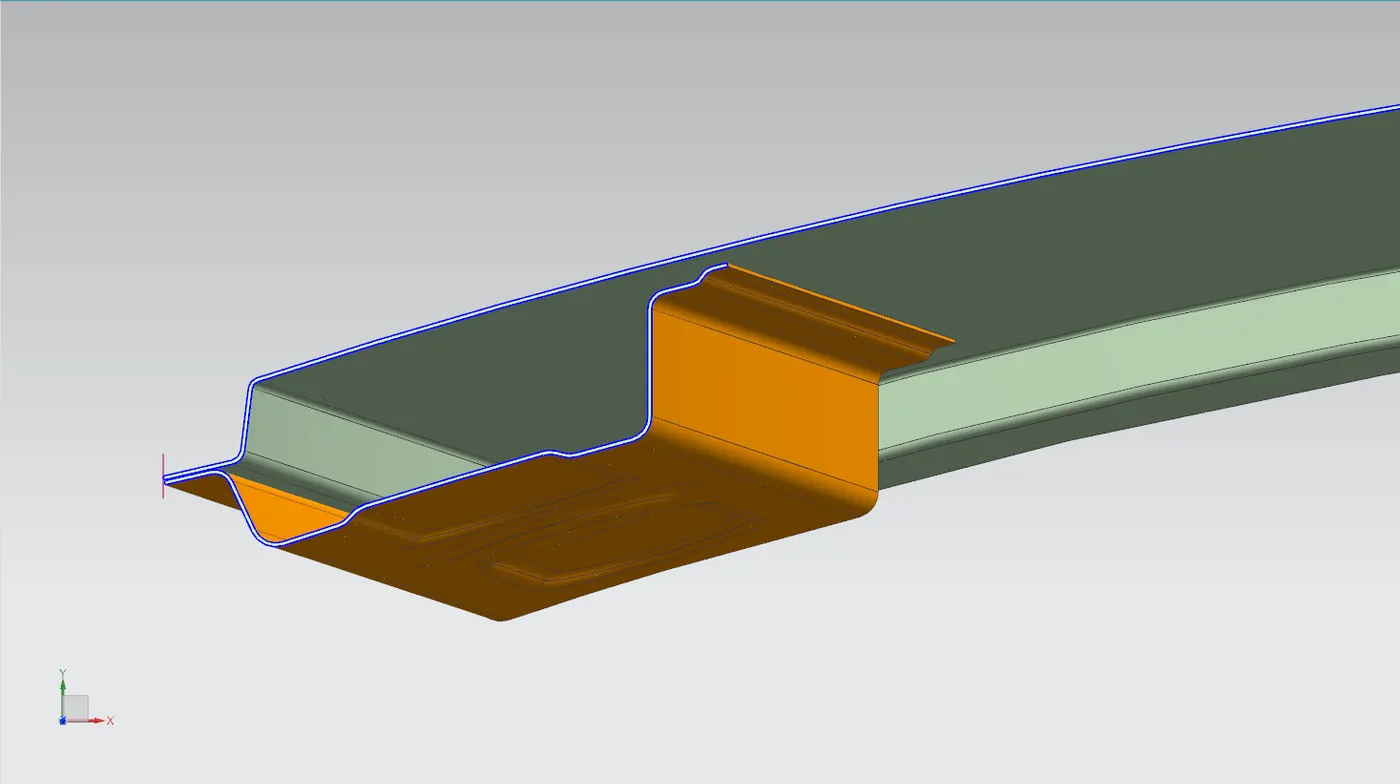
2. SECTION MODULUS ANALYSIS
Front Roof Rail
Bow Roof 1
Center Roof Rail
Bow Roof 2
3.CURVATURE STUDY
The above picture will show the standard for calculating the curvature study,
- [0-Y] – Considered as the Snow Load Prediction
- [-3-Y] – Considered as the Heat Distortion Criteria
HEAT DISTORTION CRITERIA
Heat Distortion is the temperature at which the metal softens and deforms under a specific load. This study is done to check whether the ability of the roof to withstand high temperature with respect to the positioning of the reinforcements which helpsto increase the strength.
W = [1.73 x 10^(-3) x L] + [1.85 x 10^(-8) x (R^2)/t] + [1.10x10^(-3) x l] - 2.68
Judge mental Condition : OK< 2.7 > 3.1
Where,
L = Roof Length in X-Direction[mm](Roof dimension in 0-Y)
R = Roof curvature
R = 2(Rx*Ry)/(Rx+Ry)
Rx = X curvature
Ry = Y curvature
t = Roof plate thickness [mm]
l = Bow Roof Span [mm]
| Heat Distortion Criteria | ||||||||
| BOW's | Rx | Ry | R | l | L | t | W | RESULT |
| FR-BR1 | 5733.4941 | 2628.1422 | 4180.818 | 417.6 | 2123.6 | 0.75 | 1.8843 | OK |
| BR1-CR | 4938.9 | 6327.5 | 5633.2 | 390.5 | 1.8546 | OK | ||
| CR-BR2 | 3974.8962 | 10589.1741 | 7282.035 | 429 | 1.8969 | OK | ||
| BR2-RR | 3278.8 | 14590.65 | 8934.725 | 337.3 | 1.796 | OK | ||
SNOW LOAD PREDICTION
Snow Load Criteria study is done to check the withstand ability when the snow loads over the roof during winter in snow fall regions. This study will also analyze the roof that whether the permanent deformation occurs after removing the snow load. That it may bend but needs to be bounce back to its original position.
Qr = [Iy x t^2] / [α x s x [(Rx + Ry)/2]^2 x 10^(-8)]
Where
α = Y(Ly-Y) x Lx2 x 10-12 , My = Y(Ly-Y)
Judgement condition = Qr ≥ 3.1
250 ≤ s ≤ 380
t = Roof plate thickness [mm]
Ly = Distance between the front and rear roof Rails on the Vehicle along with 0Y [mm]
Lx = Distance between the Left and Right end of the roof on the Roof BOW [mm] i.e (Width of the roof panel exposed on the surface)
Y = Distance front Front Roof Rail to Roof BOW[mm]
s = Distance for which Roof BOW bears divided load [mm]
s = L1/2 + L2/2
Iy = Geometrical moment of inertia of Roof BOW (Y cross-section )[mm4]
Rx = Lateral direction curvature radius of roof panel Y cross-section on Roof BOW [mm]
Roof panel curvature Radius of the Length Lx in Front view
Ry = Longitudinal Direction curvature radius of the Roof panel X cross-section on Roof BOW [mm]
Roof panel X curvature radius of length ‘s’ in Side view
Calculation Table
| Result- | |||||||||||
| Bow position | Iy | α | Lx | Ly | Y | S | Rx | Ry | t | Qr | Result |
| FR and 1st | 1.97 | 1.05 | 1119.7 | 2033.7 | 569.65 | 404.05 | 4105.6 | 15113 | 0.75 | 3.85 | OK |
| 1st and CTR | 2.27 | 1.21 | 1081.7 | 2033.7 | 979.65 | 409.75 | 3794 | 10543 | 0.75 | 2.09 | Not OK |
| CTR and 2nd |
1.87 |
0.91 | 1059.4 | 2033.7 | 1488.1 | 383.15 | 4231.2 | 6602 | 0.75 | 3.03 | Not OK |
Conclusion
From above calculations it is clearly Seen That "W" value is ok. But in snow loading criteria i.e, "Qr" value in last two Places is not getting Satisfied. So in order to maintain good strength we will introduce there two embosses to get there some strength.
Final Roof Design
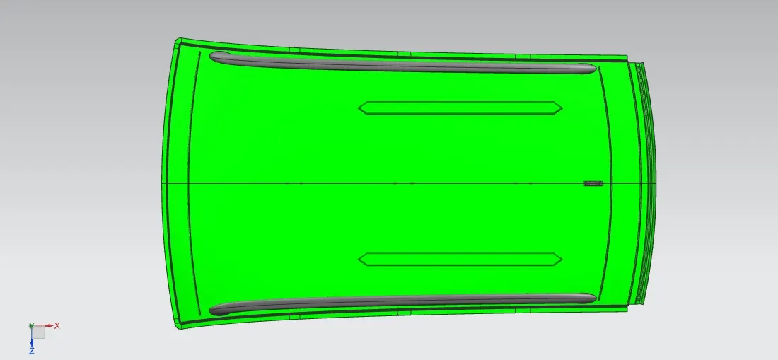
3mm Embosses are provided between Center Roof Rail And Bow Roof 2 from outside to inside direction As Qr value between them is failing.