Roof Design
ROOF DESIGN
AIM:
For the Given Roof Styling, create an Assembly by developing the essential flanges for the outer roof and creating the reinforcements. Provide appropriate dimensions and check for Draft Analysis
Do a curvature study on the roof and perform calculations to determine the position of the Bow-roofs.
INTRODUCTION:
Automobile roof is the upper portion of an automotive which protects the passengers/riders riding inside the automotive from the outside weather conditions eg- rain, sun, snow, and dust. Various environmental conditions are taken into account for designing the roof. Even though it serves as a styling surface roof should be provided with proper reinforcements for safeguarding passengers. Vehicle roofs are vulnerable to high heat conditions & moderate load during snowy conditions. Heat load calculation & snow load calculation are done to get a proper design of roof rails. This ensures the safety of the passengers in the vehicle.
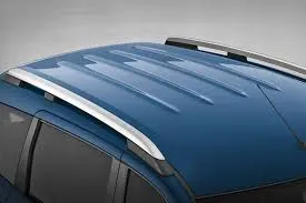
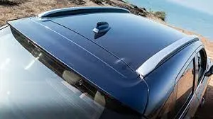
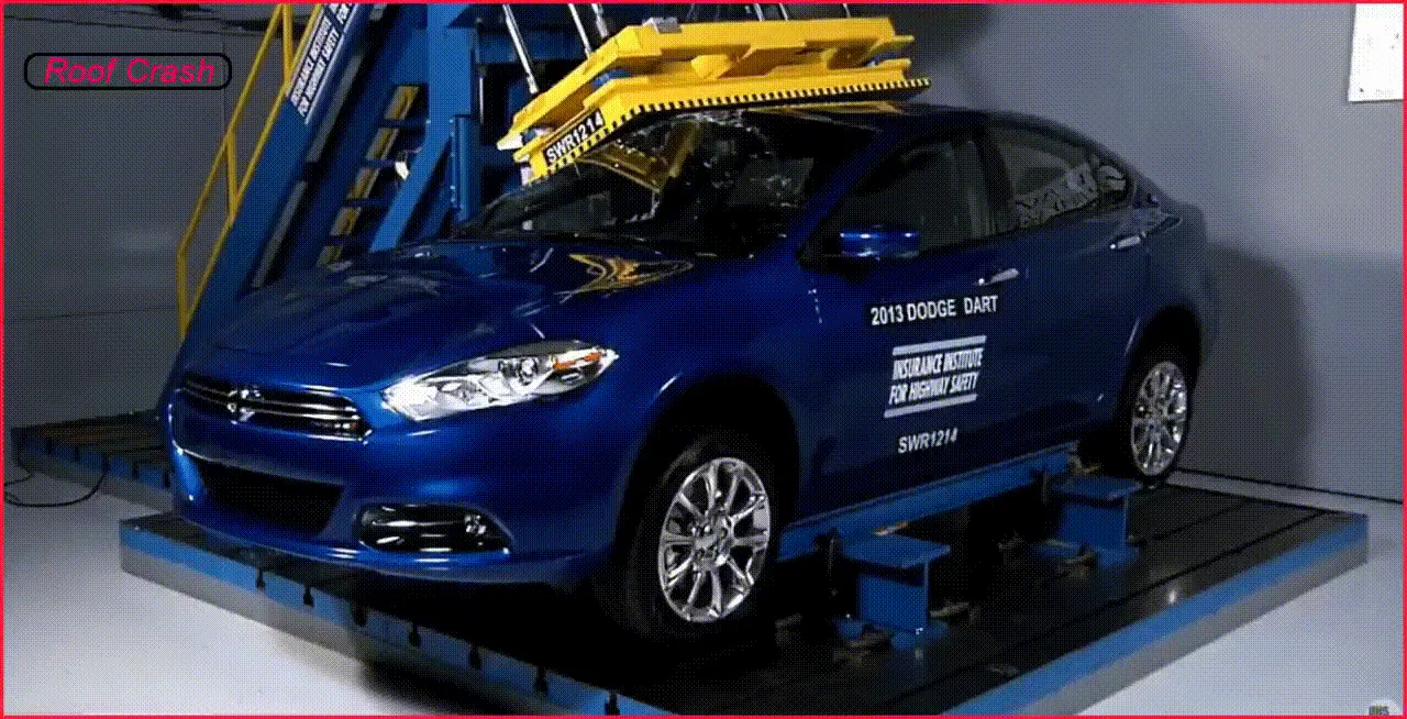
ROOF CRUSH TEST:
Roof crush test is the design given by the IIHS (Insurance Institute of Highway Safety). After analyzing the many accidents IIHS has then fixed some regulations, on how to perform the crush test.
IIHS gives the rating based on this test. For this, they consider two points while giving the rating
- How fast the car can reform to its original shape after the rollover and
- How deep is the protrusion after the rollover.
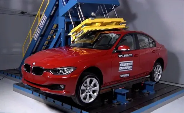
GOAL OF ROOF CRUSH TEST:
To minimize the protrusion into the occupant compartment, so that the seatbelts and airbags can do their job of protecting the occupant.
CONDITIONS TO FOLLOW FOR ROOF CRUSH TEST:
Two conditions should be followed for the roof crush test, they are
INITIAL CONDITION:
Close and lock all doors
Close all windows
SECOND CONDITION:
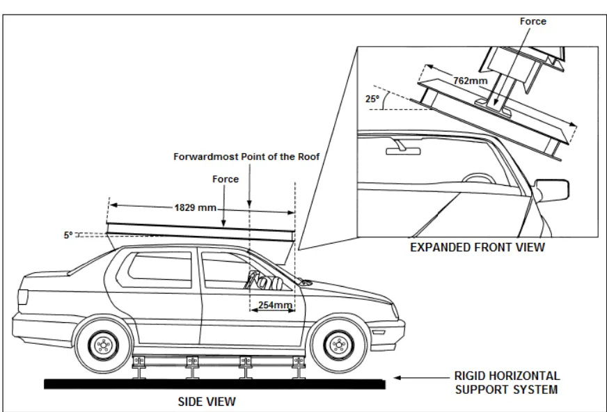
Fix the body sill or chassis frame on a hard lever surface horizontally
METHOD FOR APPLYING THE FORCE:
The load is applied in such a way that 5 degrees is titled from the front end to the rear end and the load will be 180mm in length and 750mm in width. The load is applied at the position of 25 degrees from the flatness of the roof. The load is applied on the roof for almost 120 sec and the crush speed at which the load is applied is 13mm/sec or less than that.

RESULT:
If the displacement goes above the requirements level then we have to increase the bow roof thickness or add more mastics points to increase the strength. The stronger the roof the better it can protect the occupants in the roll rover crashes.
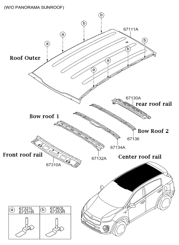
NOW LETS SEE WHAT ARE ALL THE PARTS ARE THESE IN ROOF:
- OUTER ROOF
- FRONT ROOF RAIL
- BOW ROOF 1
- CENTER ROOF
- BOW ROOF 2
- REAR ROOF RAIL
OUTER ROOF:
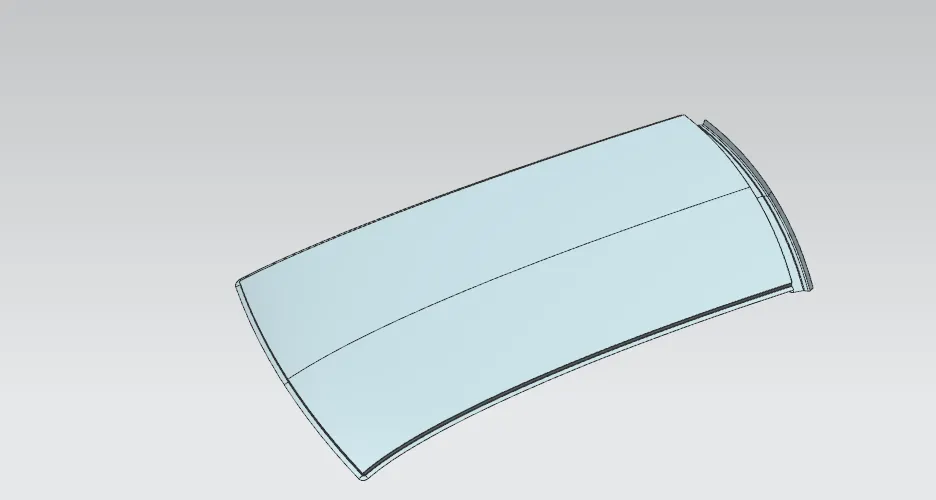
An Automobile roof or car top is the portion of an automobile that sits above passenger compartment, protecting the vehicle occupants from sun, wind, and other external elements.
FRONT ROOF RAIL:
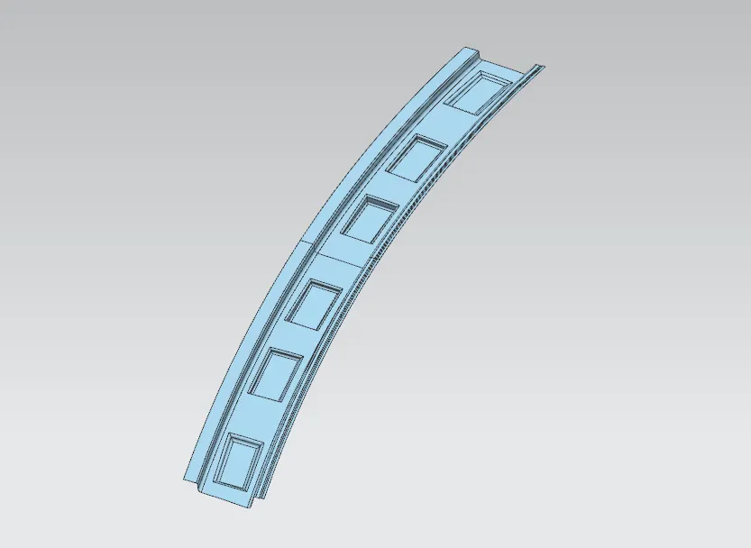
Front roof rail is the one that joins the windshield glass, the body side outer, and the inner panel.
BOW ROOF 1 AND 2:
The bow roofs are given to improve the torsional stiffness and load-bearing capacity of the roof structure. The number of bow roofs present depends on the overall size of the roof. Presently in this project, two bow roofs are added.
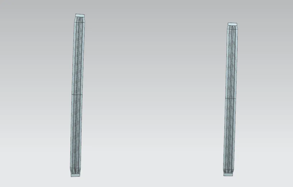
CENTER ROOF:
Central roof rail helps in providing effective support to the flat area of the roofs as it is more susceptible to failure under the action of load, generally, central roof rail is placed at the center of the roof which is connected to the B-pillar support structure. This central roof rail helps in adding strength to the roof during the rollover test.
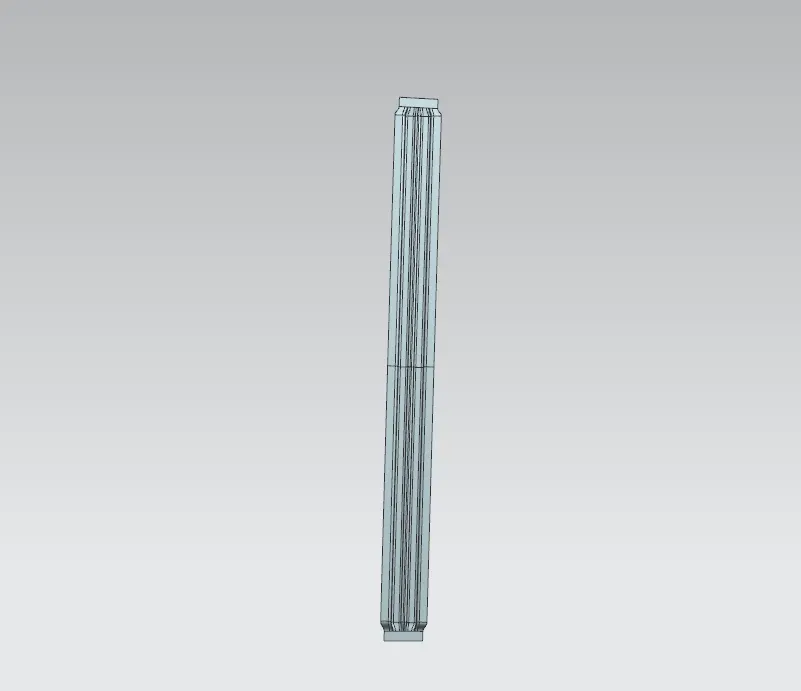
REAR ROOF RAIL:
Roof rail is the one that joins the back door and the body side outer.
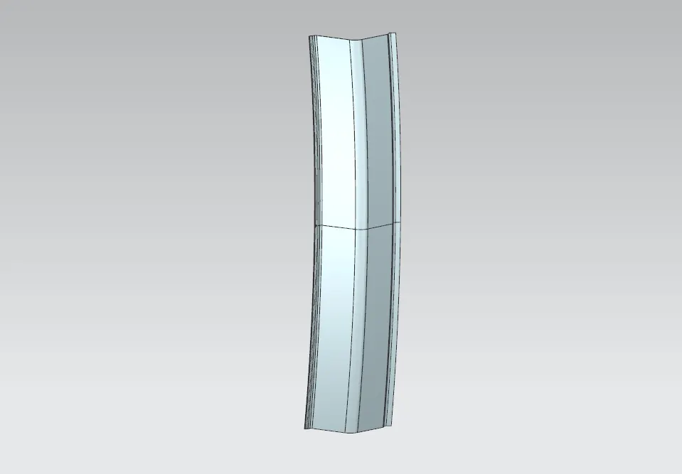
ROOF WITH RAILS:
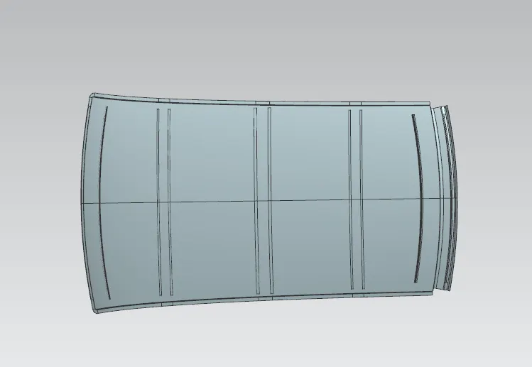
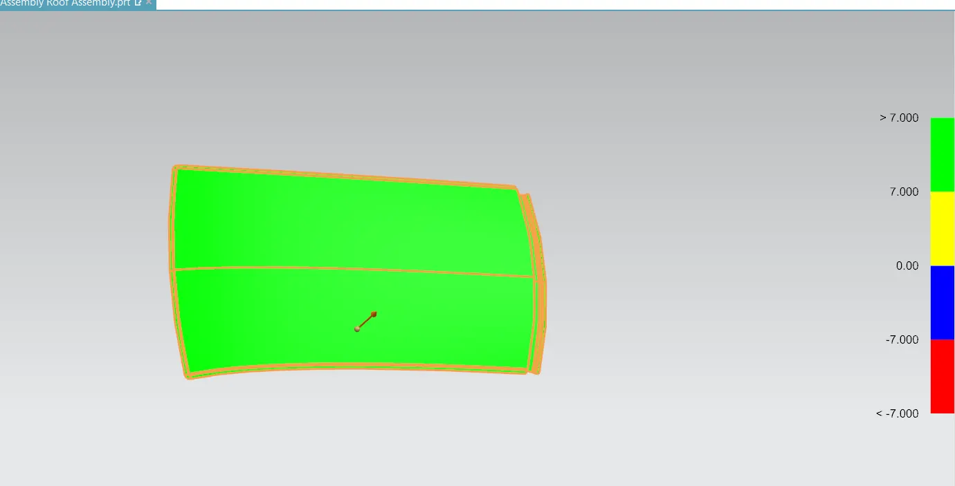
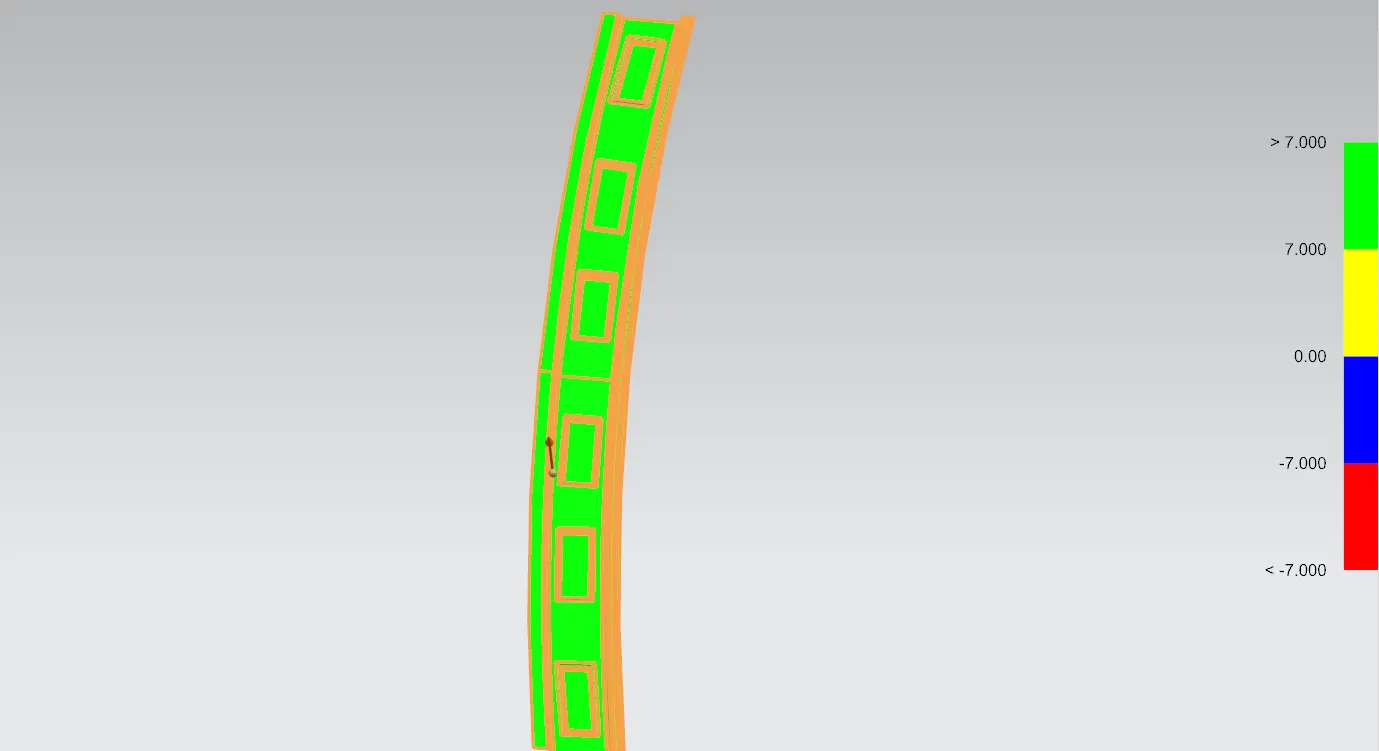
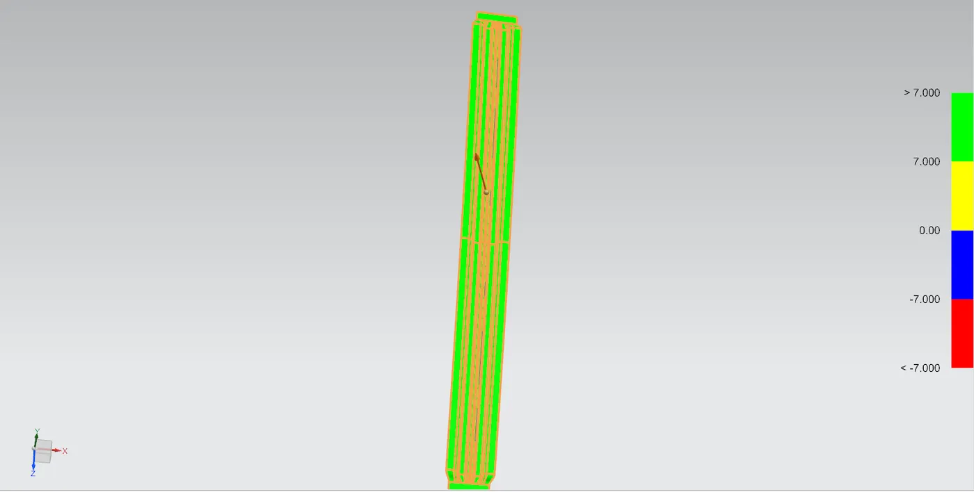
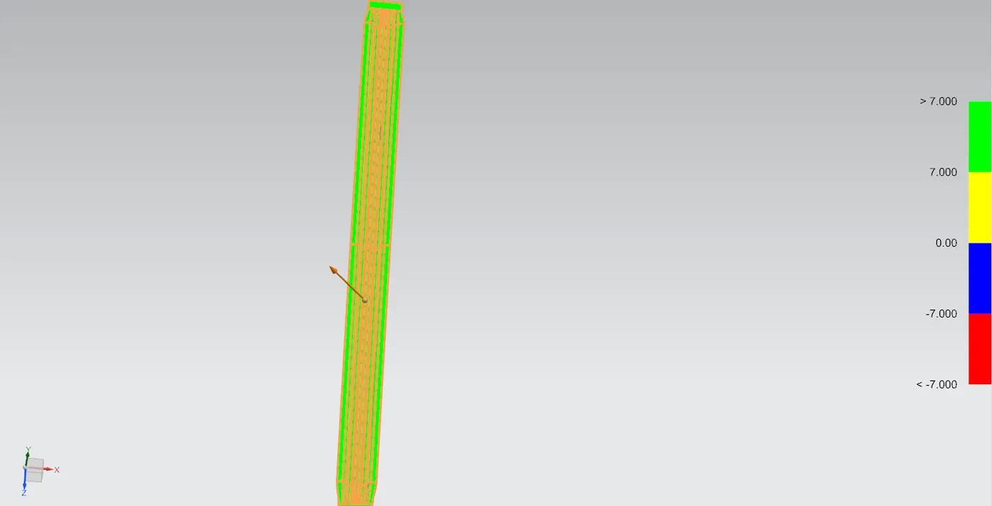
DRAFT ANALYSIS:
DRAFT ANALYSIS FOR ROOF OUTER:
DRAFT ANALYSIS FOR FRONT ROOF RAIL:
DRAFT ANALYSIS FOR CENTER ROOF RAIL:
DRAFT ANALYSIS FOR BOW ROOF RAILS:
BOW ROOF RAIL 1
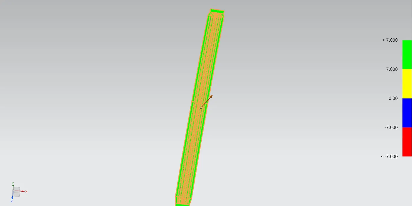
BOW ROOF RAIL 2
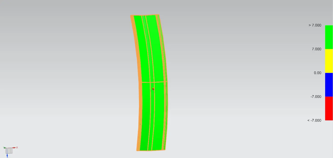
DRAFT ANALYSIS FOR REAR ROOF RAIL:
PROCEDURE TO DESIGN ROOF OUTER ON NX CAD:
Open the given model in NX which is the styling surface of the car's roof.
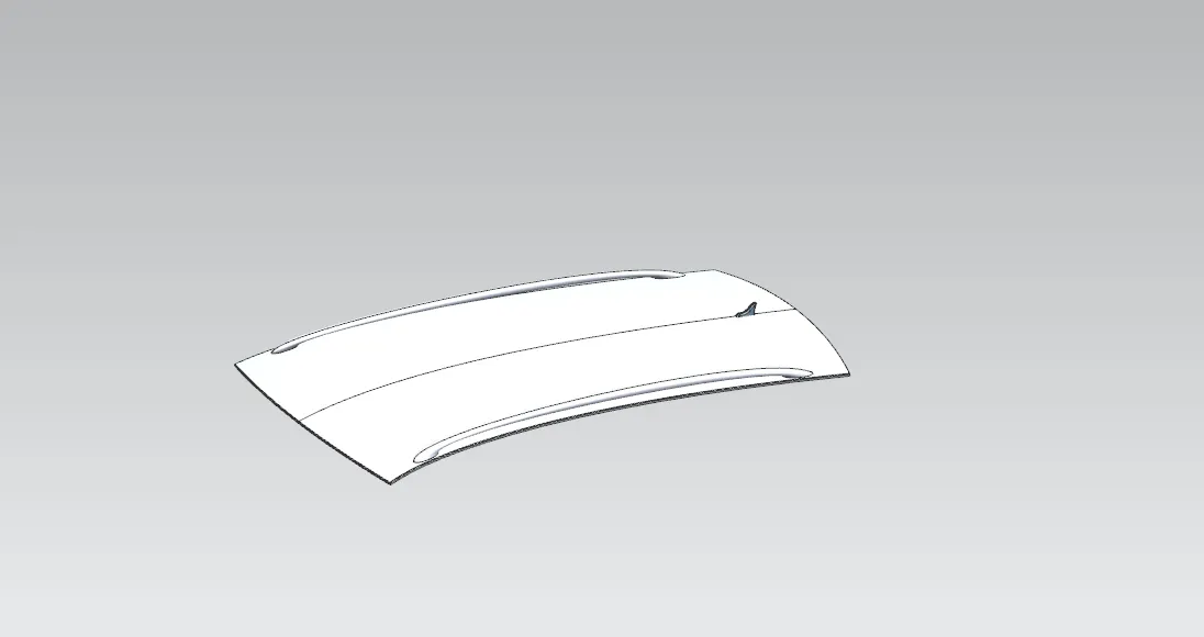
In this challenge, we will be creating the Roof's outer panel, Front roof rail, Rear roof rail, Center reinforcement and Bow roofs.
ROOF OUTER PANEL:
First, we will be extracting the top half portion of the roof surface. Since the roof surface is symmetrical in shape, we can easily work on half of the portion and reflect it at the end to create the whole roof.
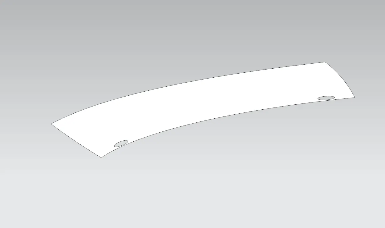
Untrim this surface in order to avoid the holes. Extract the outer boundaries of the original half surface and project it on the untrim surface to get the exact outer edge of the roof.
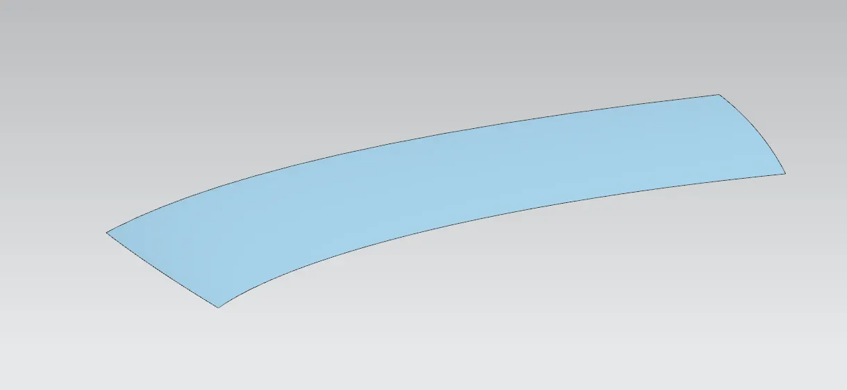
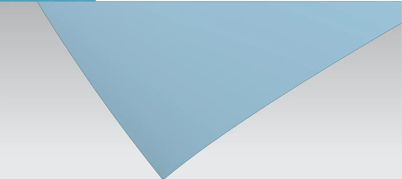
The corners of the roof surface are sharp so use the bridge curve and trim the sheet and trim the sharp edges.
Now will be creating flanges by using the law extension command.
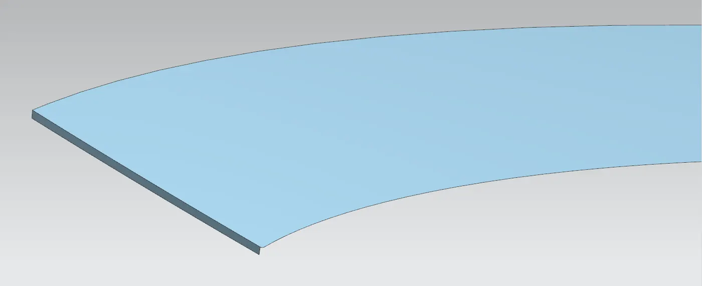
From the edge of the law extension create another law extension.
Similarly, by following the same procedure we can create a flange on the other edges as well.
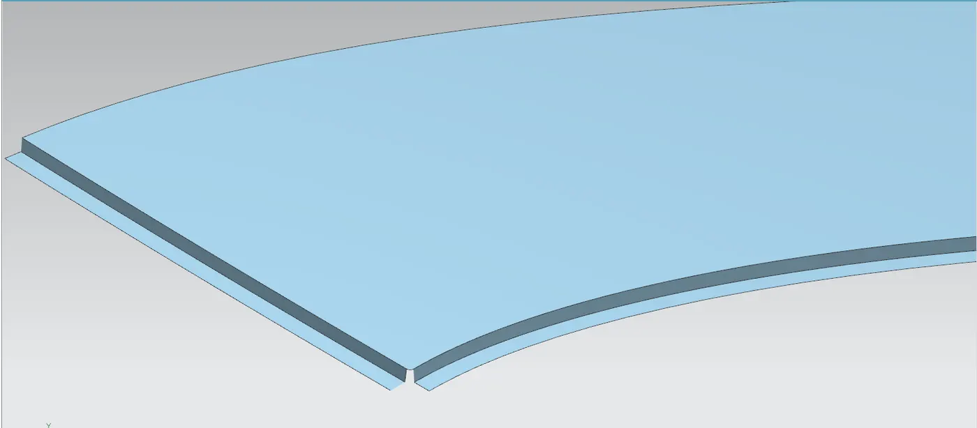
Using the through curve mesh command to create a surface on the corners by giving guide curves and support of the surfaces.
Sew these surfaces together and give the required fillets.
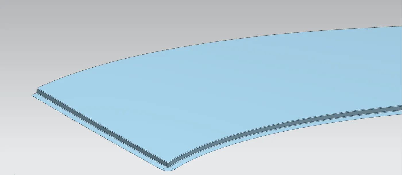
Now follow the master section given for Rear roof rail and create the Additional area.
For the rear end, there should be an additional area that helps to hold the back door without hitting the roof.
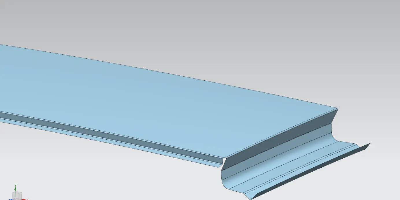
FRONT ROOF RAIL:
First Create the Part file for the Front roof rail in the assembly file.
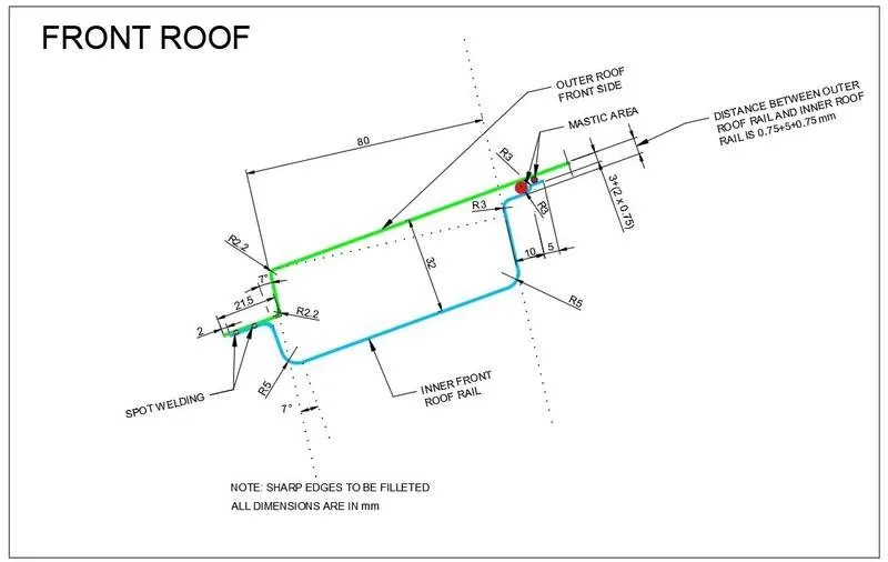
Following the master section which is given to us as input, we will be creating the Front roof rail.
FRONT ROOF RAIL MASTER SECTION:
Use the command wave geometry linker and select the extracted roof and ditch area part
Now offset the surface to 32mm and ditch area to 1.5mm(For spot welding)
Use Law extension command for ditch area to create the lower part of the front roof area.
Extend and attach the offsetted sheet till it touches the law extension.
Trim and extend the sheet and law extended sheet.
Then use Offset curve in face command and select the lower edge and set it to 80mm and trim the unwanted sheet.
Use law extension to build the lower side for the other part at an angle of 25 degrees.
Now offset the surface for 5+0.75+0.75mm for the mastic points for the first curve, then trim and extend.
Then use offset curve in face and set it for 10mm.
Then offset the surface again for 3+0.75+0.75mm for the mastic points for the second curve and use trim and extend.
Then use offset curve in face and set it for 5mm.
Now fillet the edges to 3.75 thickness.
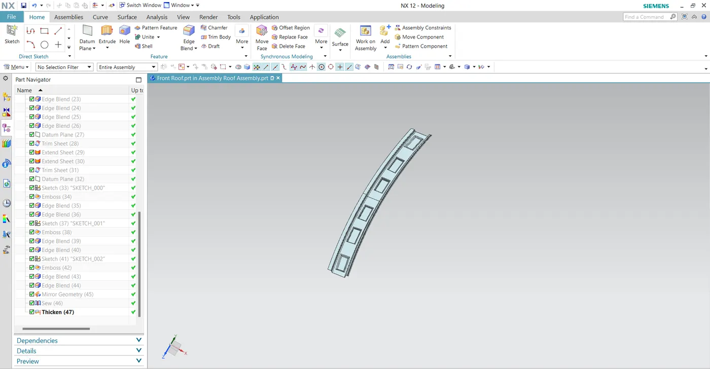
Now draw some sketches and create embossed. Then extend the sheet and trim the sheet so that there is no gap after mirroring.
Now mirror the sheet and see it.
Thicken it for 0.75mm.
REAR ROOF RAIL:
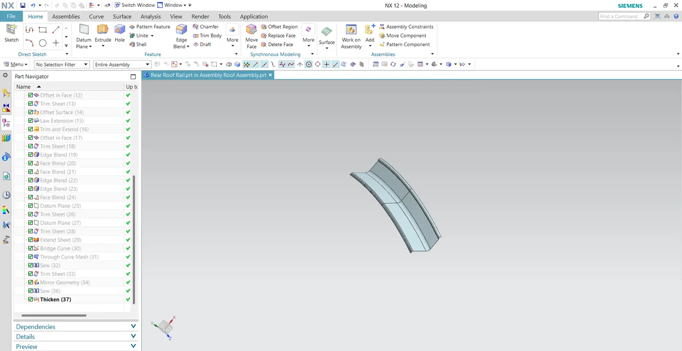
First Create the Part file for the rear roof rail in assembly part file.
Following the master section which is given to us as input, we will be creating the Rear roof rail.
MASTER SECTION FOR REAR ROOF RAIL:
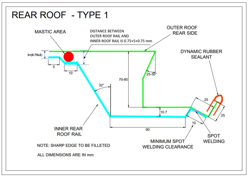
Similar operation which was performed in the Front Roof Rail needs to be followed to create the Rear Roof Rail.
CENTER ROOF RAIL:
First Create the Part file for the Center Roof Rail.
Following the master section which is given to us as input, we will be creating the Center Roof Rail.
MASTER SECTION OF CENTER REINFORCEMENT RAIL:
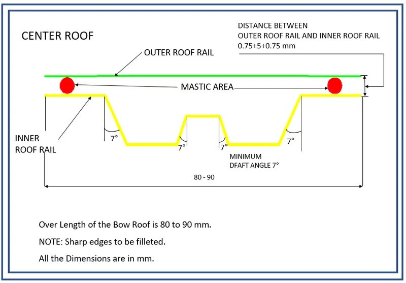
A center reinforcement is created to provide additional strength to the area where the roof surface is flat.
Use the Command Wave Geometry [linker and select the extracted roof and the ditch area part.
Use a datum plane on the curve at 50%.
Use the Intersection curve command then select the face and the datum plane at intersection line will be created.
Then offset the curve in the face for 20,40,55,75 and 95.
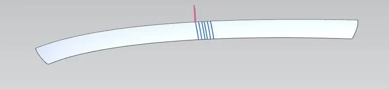
Trim sheet by selecting the curves.
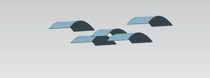
Use law extension command and join the sheets at 7 deg.
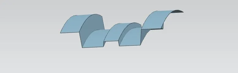
Blend the edges with the edge blend command.
Now offset the ditch area to 1.5mm in a downward direction.
Now use bridge command and sketch a curve that can be used as a guide curve.
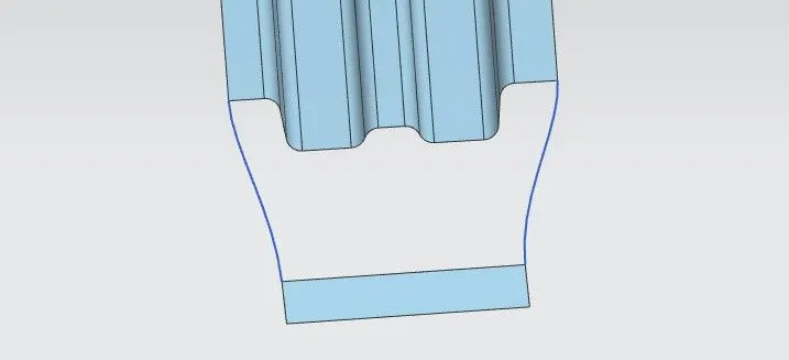
Now use through curve mesh command to join these surface.
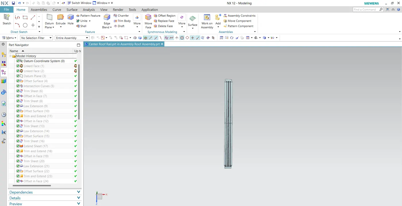
Then extend sheet and trim the sheet so that there is no gap after mirroring.
Now mirror and sew it.
Thicken it for 0.75mm.
BOW ROOF RAIL 1 AND 2:
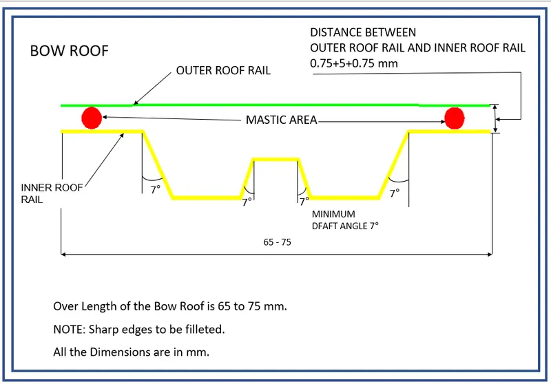
A similar operation which were performed in the Center Roof Rail needs to be followed to create Bow Roofs 1 and 2.
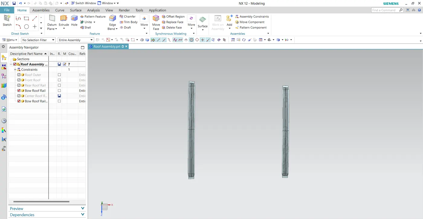
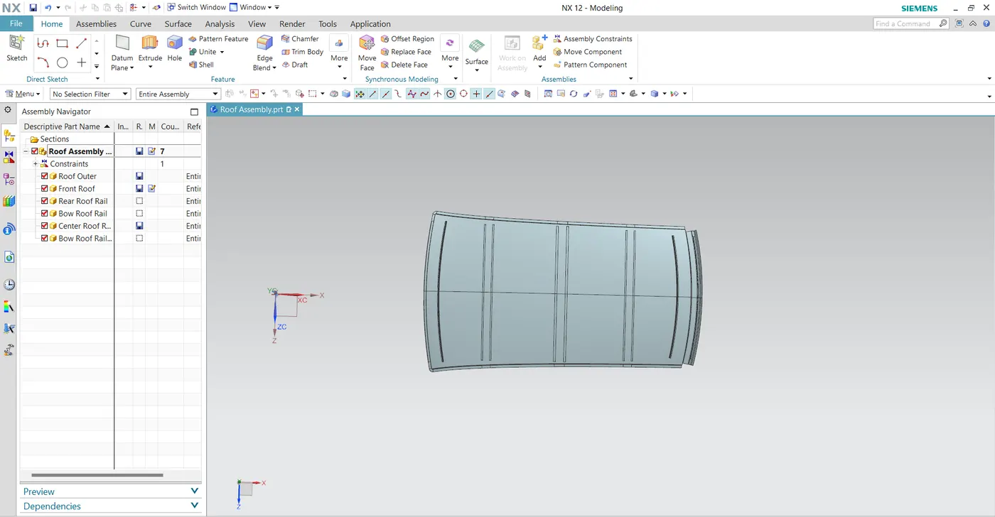
Roof has been designed by considering all the parameters and consideration:
HEAT LOAD CALCULATION:
The heat distortion study plays an important role in sheetmetal application. Heat distortion is temperature limit above which material cannot be used for structural application. This study is useful to find where the materials starts to soften when exposed to a fixed load at elevated temperatures. In order to avoid the bending, damage of the roof based on the heat distortion temperature. This study will help to locate the position of the bow roof rails to give enough strength.
Bow- Roof Prediction Formula:
W = [ 1.73 x 10^(-3) x L] + [1.85 x 10^(-8) x (R^2)/t] + [1.10 x 10^(-3) x I] - 2.68
Where,
L = Roof Length in X-direction[mm] (Roof dimension in 0-Y)
R = Roof Curvature
R = 2(Rx*Ry) / (Rx+Ry)
Rx = X curvature
Ry = Y curvature
t = Roof plate thickness [mm]
I = Bow Roof Span [mm]
Judgment condition: W<2.7
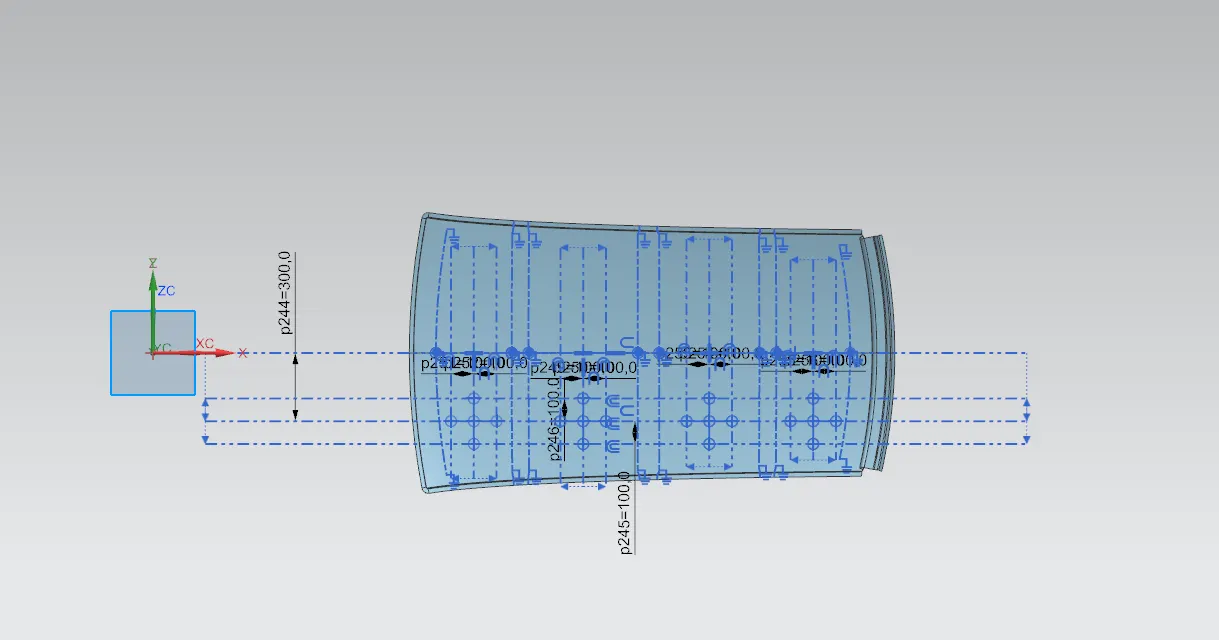
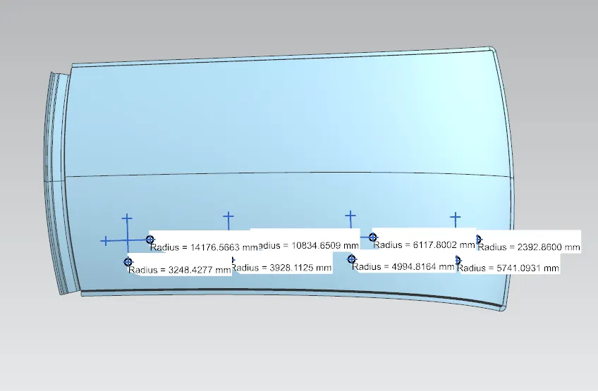
CALCULATION:
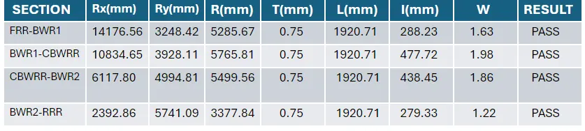
From the above table, it can be concluded that all values of 'W' are less than 2.7, which implies the position of roof rails are as per standard.
SNOW LOAD CALCULATION:
Snow load criteria study is used to check the durability of the roof to withstand the snow fall on the roof and reflex it is original shape without any permanent deformation after load being removed.
Qr = [Iy x t2] / [ α x s x [(Rx + Ry)/2]^2 x 10^(-8)]
Where
α = My x Lx2 x 10^-12, My = Y(Ly-Y)
Judgment condition = Qr ≥ 3.1
t = Roof Plate thickness(mm)
Ly = Distance between the front and rear Rails on the Vehicle along with 0Y(mm)
Length of Roof panel with the center point between Roof rail front/Rear as the reference point of the front and the rear
Lx = Distance between the Left and Right end of the roof on the Roof BOW(mm)
Width of the roof panel exposed on the surface.
Y = Distance Front Roof Rail to Roof BOW(mm)
s= Distance for which Roof BOW bears divided load(mm)
s = L1/2 + L2/2
Iy = Geometrical moment of inertia of Roof BOW(Y-cross section )(mm^4)
Rx = Lateral direction curvature radius of roof panel Y cross-section on Roof BOW(mm)
Roof panel curvature Radius of the Length Lx in Front view
Ry = Longitudinal Direction curvature radius of the Roof panel x cross-section on Roof BOW(mm)
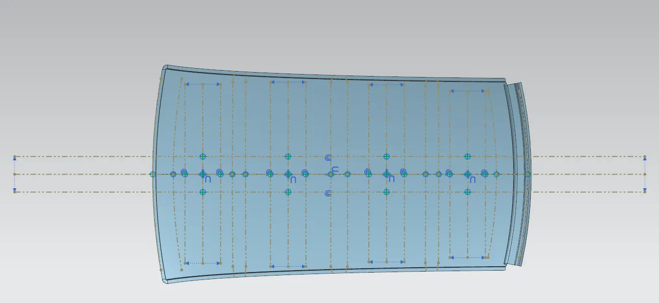
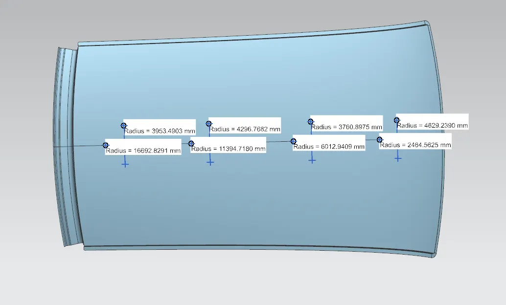
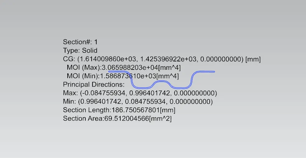
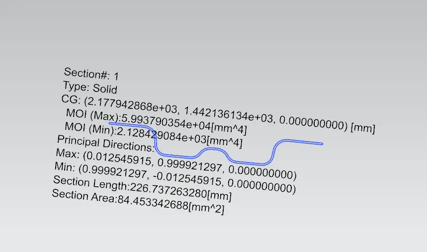
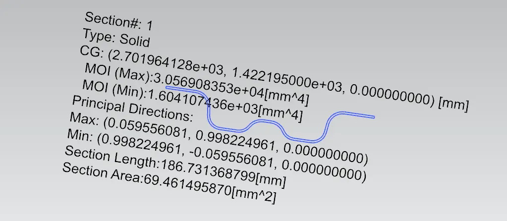
CALCULATIONS:
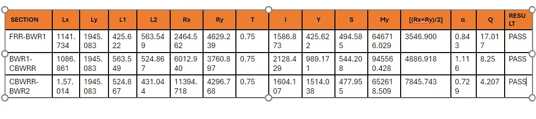
From the above calculations, the value 'Q' obtained is always greater than 3.1.
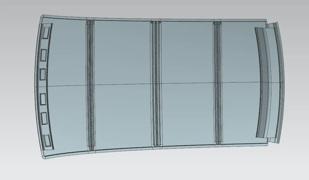
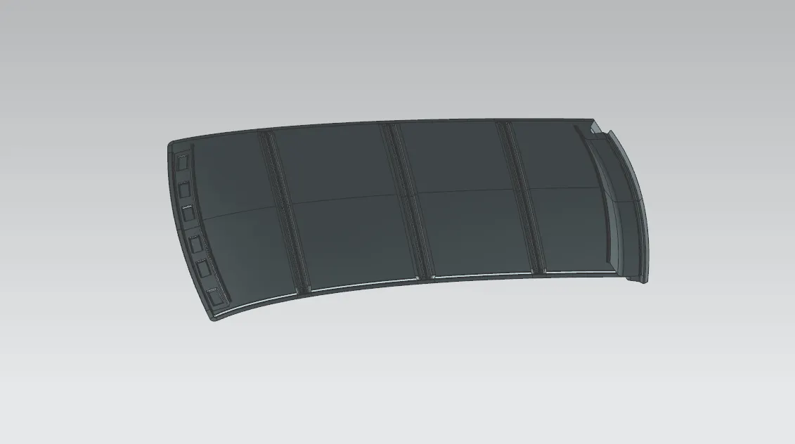
ROOF ASSEMBLY:
CONCLUSION:
Design of the roof was successfully completed using SIEMEN NX as per the given master section. The position of bow roof rails are as per the given standards. Draft analysis & section analysis ensure the manufacturability of every component.