Roof Design
AIM:
Designing a roof and related reinforcements from the current style surface is the project's primary goal. To verify the efficiency of roof reinforcement, heat load and snow load calculations will be performed on the affected part of the roof. To evaluate the manufacturability of each reinforcement, conduct a draft analysis.
INTRODUCTION:
Roof:
The top part of an automobile that shields the occupants from the sun, wind, and rain is called the roof. When designing the same, a variety of environmental factors are taken into consideration. Although the roof serves as a surface for style, it should have the necessary reinforcements to keep passengers safe. Vehicle roofs are susceptible to intense heat and moderate loads in the winter. Calculations of heat load and snow load are made in order to properly design roof rails. By doing this, the passengers' safety within the car is guaranteed.
Roof Crush Test:
The design provided by the IIHS (insurance institute of highway safety) is for the roof crush test. Following an analysis of the numerous incidents, IIHS amended certain rules on the proper way to conduct the crush test. Whenever the load is placed, it is applied with a 50-degree tilt from the front to the rear, measuring 1800 mm in length and 750 mm in width. At a position 250 from the roof's flatness, the load is applied. The force is applied to the roof for approximately 120 seconds, with a crush speed of no more than 13 mm/sec.
In order to boost strength, we must either add additional mastics points or thicken the bow roof if the displacements exceed the required amount. The better a roof can protect its occupants in rollover collisions, the stronger it is.
DESIGN PARAMETERS:
When creating a roof, the number of roof rails must be created to have sufficient strength to support the weight. In order to increase strength, bow roofs are typically attached in flatter regions. Spot welding is used to secure the front and rear roof rails to the ditch. Additionally, mastic sealants are used to secure the front, rear, and centre roof rails to the roof. Reduce the space between the bow roof and the roof rails for improved NVH. When designing roof rails, the following factors are taken into consideration.
- Visibility criteria
- Head clearance
- Curvature study
- Heat distortion and snow load criteria
- Draft analysis
Master Section:
These are the 3D model's cross-sectional data. To communicate the functional requirements of the product to the design engineer, OEMs and the automobile industry frequently utilize these master sections. It provides the dimensions that should be considered while creating a specific part or component, including height, breadth, length, radius, and clearance. All the designed parts given below are made using the master section.
1. Front Roof Rail
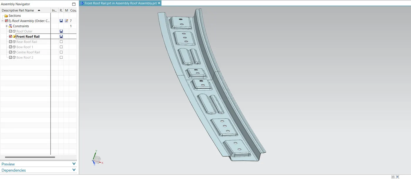
In addition to mounting the brackets for various elements, like the rear-view mirror and room lamp, the front roof rail reinforces the roof surface to give it more strength. The visibility criteria determine the width of the front roof rail. In order to prevent a person from feeling claustrophobic, the front roof rail's depth is chosen such that there is adequate headroom between the driver's head and the roof rail's end surface.
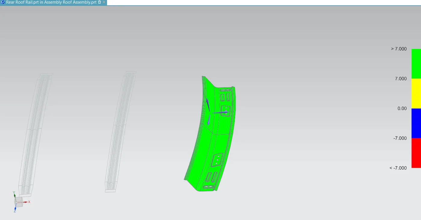
2. Rear Roof Rail
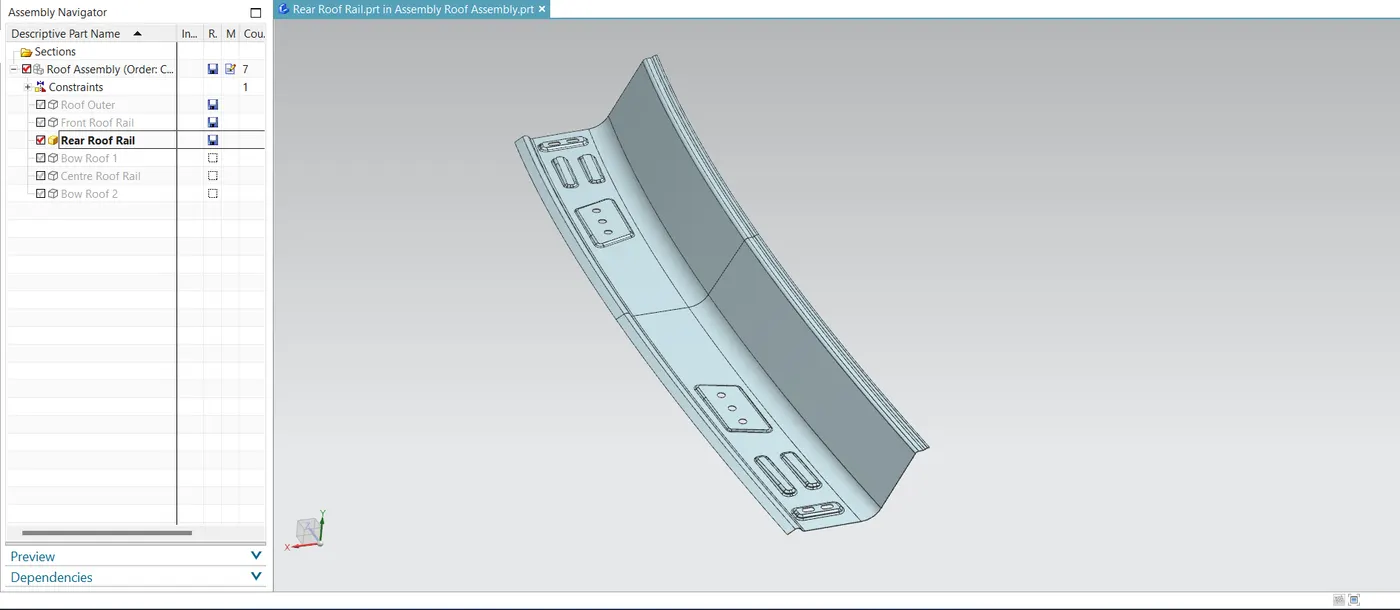
It is the reinforcement that is attached to the roof panel's back side. This item is used to attach panels to the bodyside and backdoor. On the rear roof rail, there is also a provision for opening the back door.
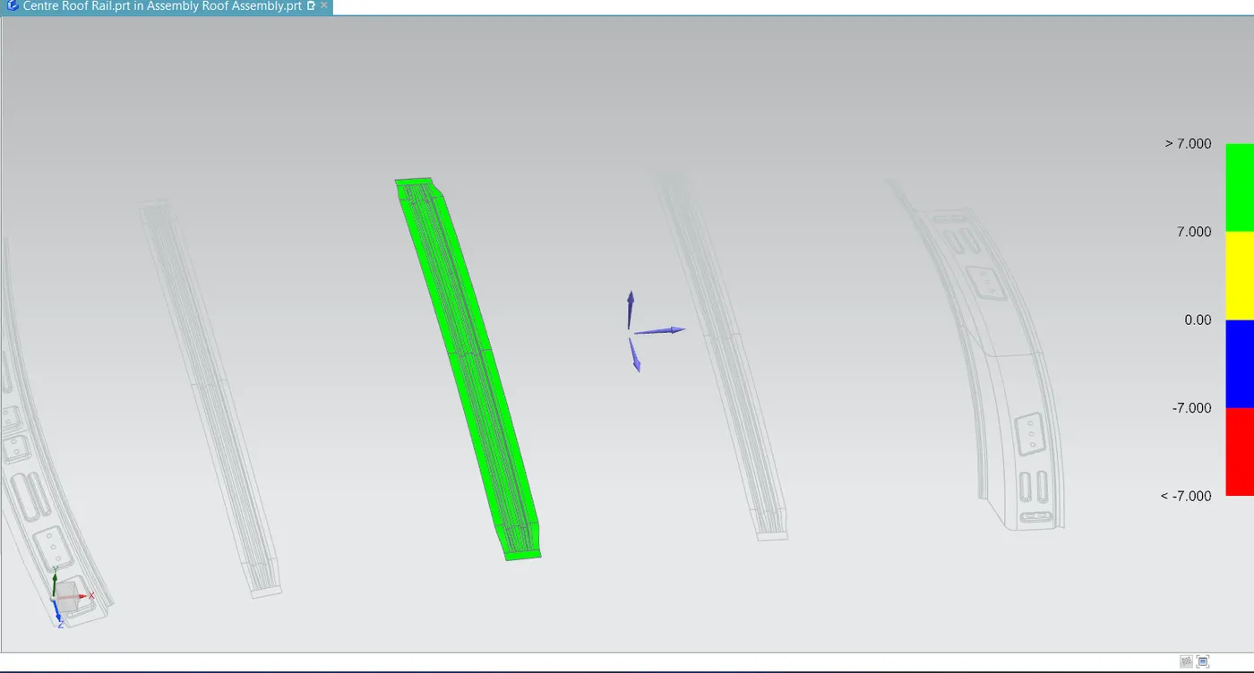
3. Centre Roof Rail
The middle section of the outer roof panel, which is supported at both ends by the B pillar, gains strength from the centre roof rail.
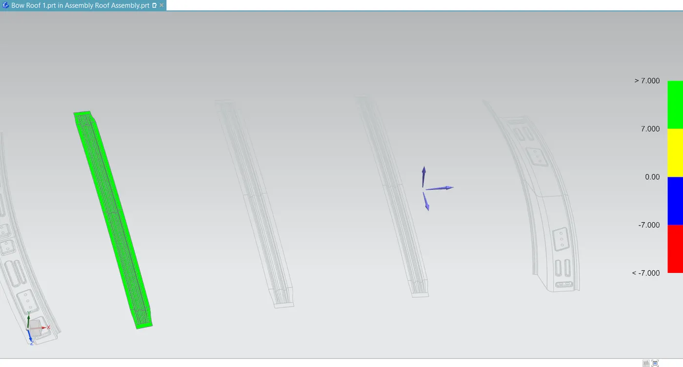
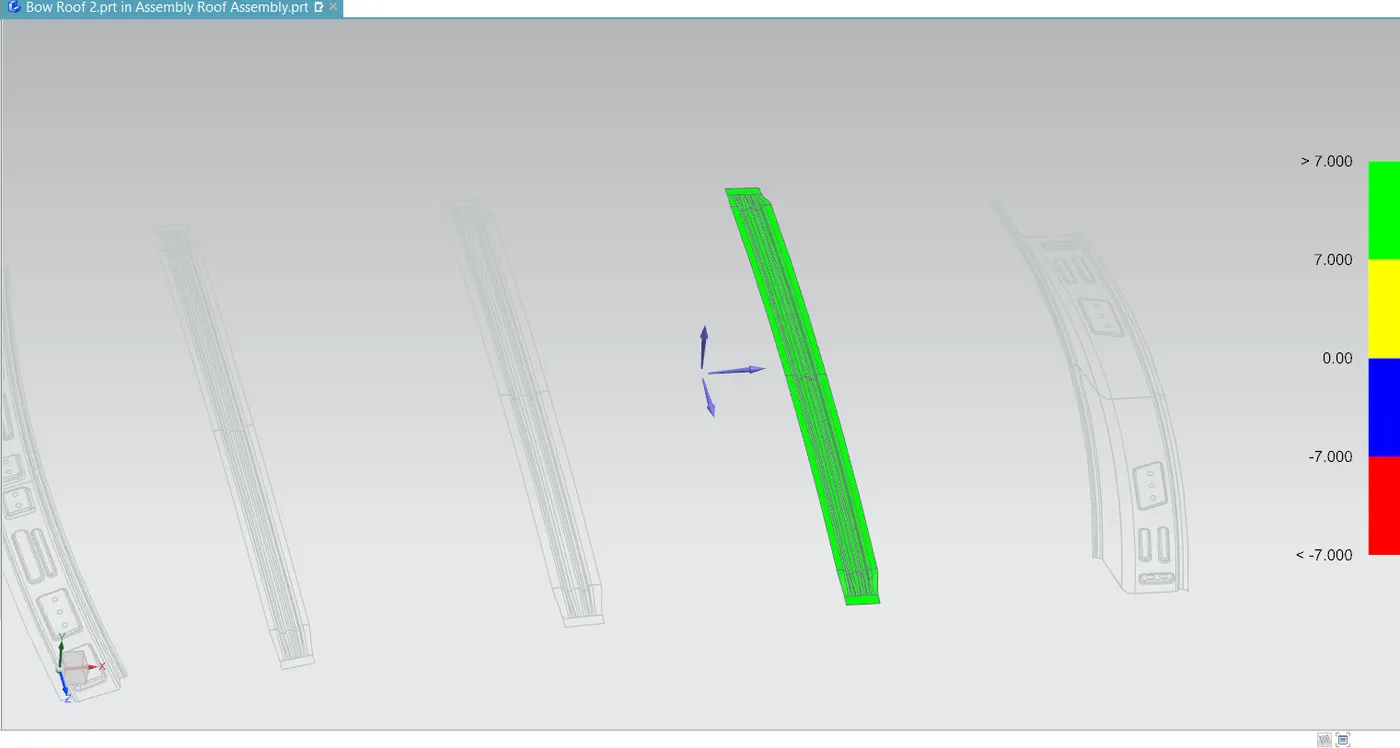
4. Bow Roof Rail
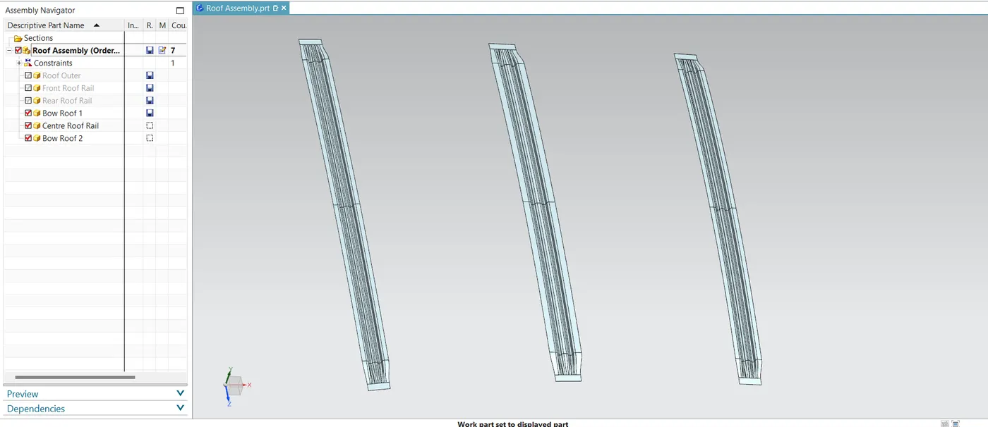
To offer extra support, these are placed between the centre roof rail and either the front or the rear roof rail. The length of the roof panel determines how many bow roof rails are needed.
DRAFT ANALYSIS:
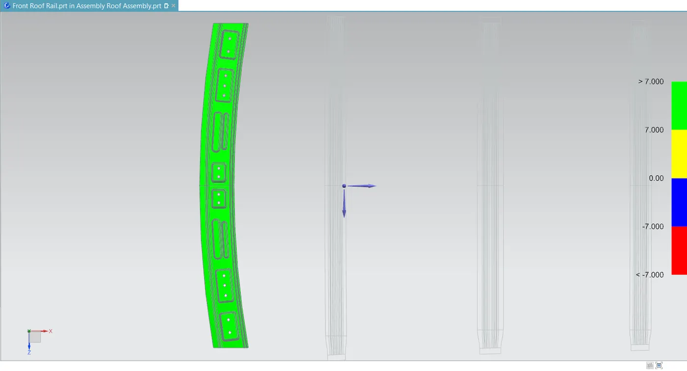
The draft analysis command lets you know if the part you drafted will be easy to remove. Zones on the analysed piece that have a deviation from the draft direction at any given point that matches present values are found using colour ranges in this type of analysis.
A minimum draft angle of 7 degree is considered for research purposes. When all of the components are facing the tooling direction, the colour green denotes a component that has passed analysis and has a positive draft angle greater than 7 degree.
FINAL ASSEMBLY:
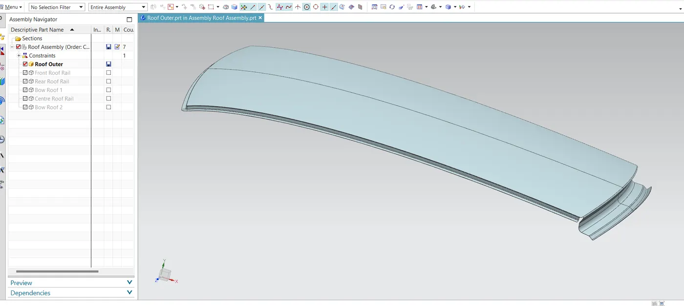
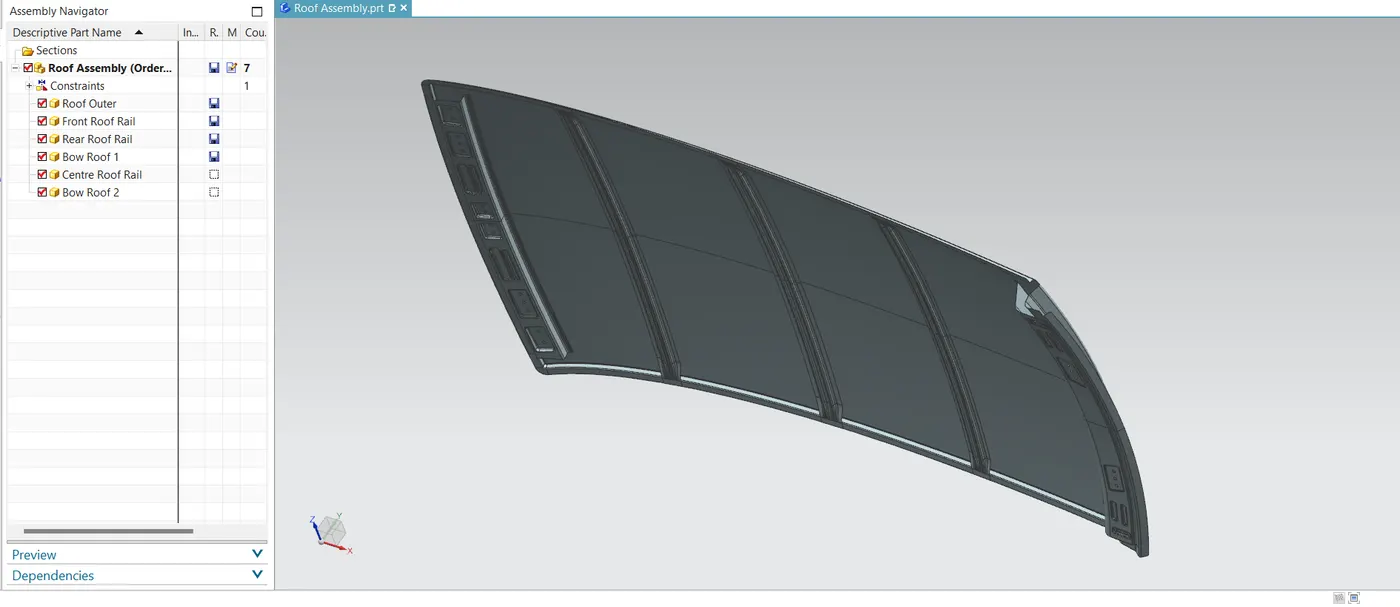
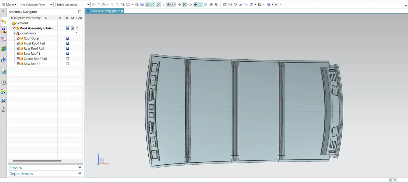
HEAT DISTORTION CALCULATION:
An essential component of Sheetmetal application is the thermal distortion study. The temperature at which a material may no longer be used for structural purposes is known as heat distortion. Finding out where the material begins to soften when subjected to a fixed load at a high temperature is made easier with the help of this study. To prevent the roof from bending due to temperature-induced heat distortion. The location of the bow roof rails to provide adequate strength will be determined with the aid of this analysis.
Bow-Roof Prediction Formula:
W=[1.73*10-3*L]+[1.85*10-8*(R2)/t]+[1.10*10-3*l]-2.68
Where,
L = Roof length in X-direction[mm] (Roof dimension in 0-y)
R = Roof curvature
R = 2(Rx*Ry)/(Rx+Ry)
Rx = X curvature
Ry = Y curvature
t = Roof plate thickness[mm]
l = Bow roof span[mm]
Judgement Condition
OK < 2.7
Calculation:
- Initially, we need to choose a plane that will be used for all of the sketches, and it should be parallel to the outside surface of your roof.
- After getting at the sketch, the roof's centre line, 0-Y, was produced. From that line, 3-Y, an offset of 300 mm, was created. Next, 3-Y was offset 100 mm and 100 mm, respectively, in the up and down direction. In a 2D sketch, the margins of the front, Rear, bow, and centre roof rail are projected (by project curve).
- after which, using the point command, the point of intersection of the points is established. I choose the intersection option, then project curve (pc) and 0-Y to generate the intersection point.
- The junction point is used to produce a line, and the line's midpoint is used to generate a vertical line.
- It is necessary to shift the vertical line by 100 mm to the right and left in order to produce an intersecting point.
- The same procedure is carried out in each situation. The sketch was completed, and the points were projected onto the outside surface of the roof's upper surface.
- Drawing the arc with the three-point option by specifying the start point, finish point, and mid-point using the Arc command. All of the vertical and horizontal points are now being caressed as this operation continues. The local radius command is used to show the radius of the constructed arc (Rx-Ry).
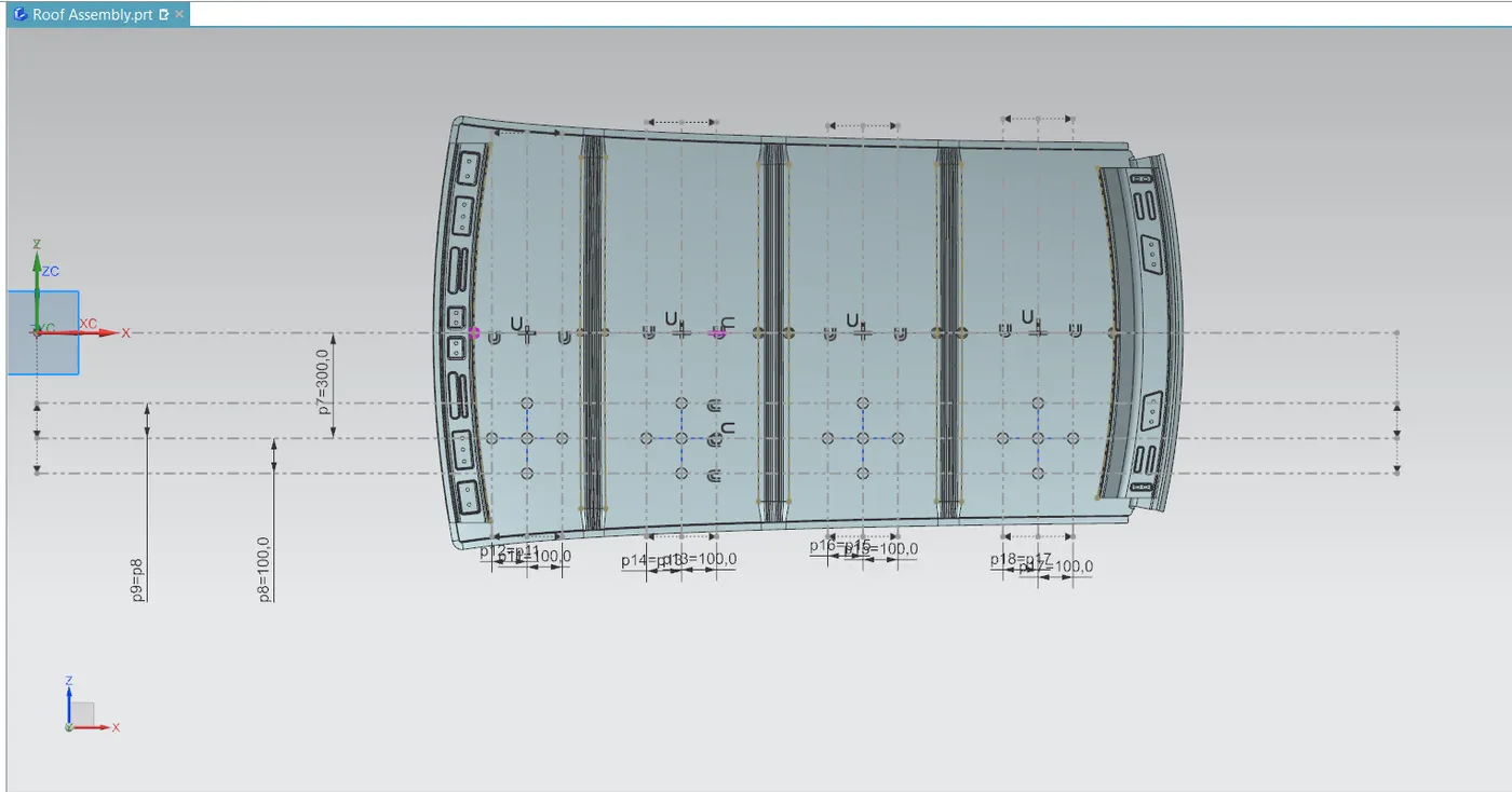
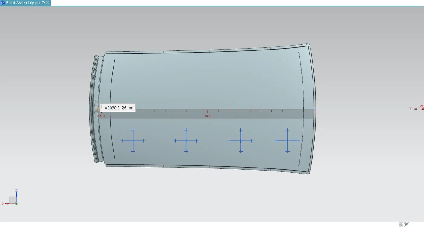
- The vertical arc is Rx and the Horizontal arc is Ry.
|
SNOW LOAD CALCULATION:
The purpose of the snow load criteria research is to determine whether the roof can sustain snowfall and return to its former shape without suffering any long-term deformation after the load is removed.
Qr = [ly*t2]/[α*S*[(Rx+Ry)/2]2] *10-8
Where,
α = My*Lx2*10-12, My = Y(Ly-Y)
t = Roof plate thickness[mm]
Ly = Distance between the front and the rear roof rail on the along with 0-y[mm]
Length of roof panel with the centre point between roof rail Front / Rear as the front and rear reference point.
Lx = Distance between the left and right end of the roof on the roof bow [mm]
The width of the roof panel is exposed on the surface.
Y = Distance front roof rail to bow roof[mm].
S = Distance for which roof bow bears divided load[mm]
S = L1/2 + L2/2
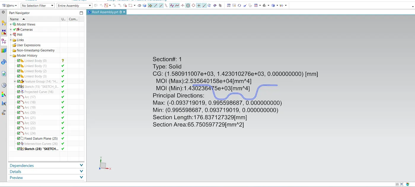
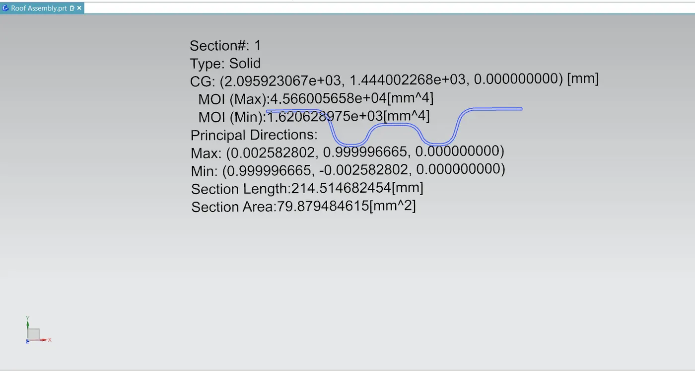
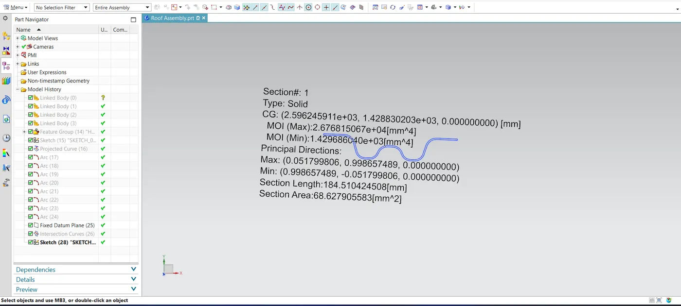
ly = Geometrical moment of inertia of roof bow (Y cross section) [mm4]
Rx = Lateral direction curvature radius of roof panel Y cross section on Roof Bow[mm]
Roof panel curvature radius of the length Lx in front view
Ry = Longitudinal direction curvature radius of the roof panel X cross section on Roof Bow[mm]
Roof panel X curvature radius of length S in side view.
Judgment condition
Qr >= 3.1
Calculation:
- First, draw a plane that will be used for all of the sketches. The plane should be parallel to the outside surface of your roof.
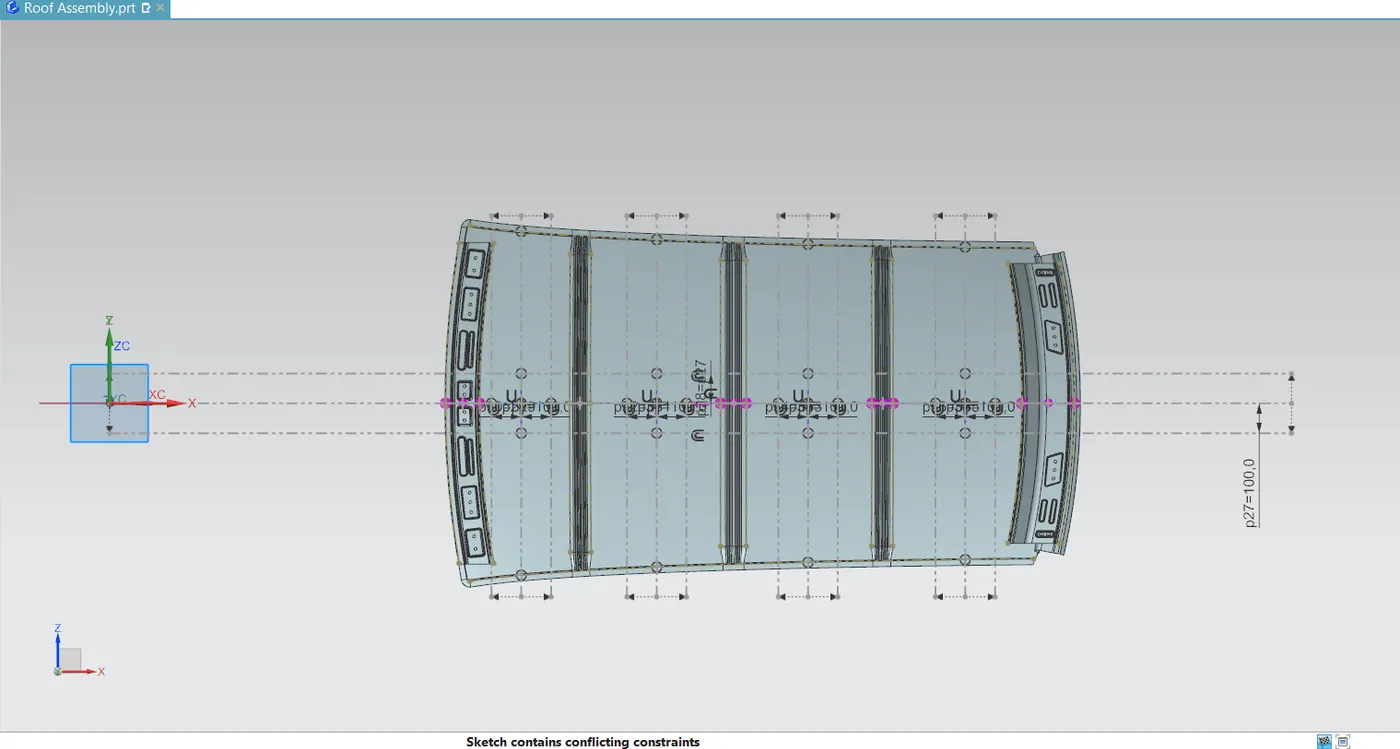
- After arriving at the sketch, draw 0-Y, which will represent the centre line of your roof. From there, it must be offset 100 mm in the up and down directions, respectively.
- In a 2D sketch, the margins of the front, Rear, bow, and centre roof rail are projected (by project curve). Then, Intersection point is created.
- The junction point must be used to generate lines, and I was able to create a vertical line by using the line's midpoint.
- The vertical line is offset by 100 mm to the left and right, creating an intersection point.
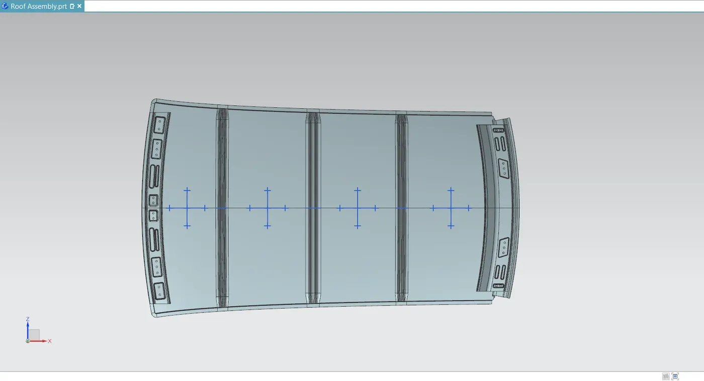
- Completing the drawing and projecting the points onto the roof's outermost surface.
- Draw the arc using the three-point option by specifying the start point, end point, and mid-point using the arc command. All of the vertical and horizontal points are now being caressed as this operation continues. The local radius command is used to show the radius of the constructed arc (Rx-Ry).
- Then, project your roof's exterior horizontal edges.
- The junction point would be created with the assistance of the intersection command.
- The vertical measurement of the intersection point formed above and below must be made with the use of fast dimension.

CONCLUSION:
Using Siemens NX, the roof design was successfully finished in accordance with the provided master sections. The bow roof is positioned in accordance with the guidelines. Draft and section analyses guarantee that each component is able to be manufactured.