Roof Design
ROOF DESIGN WORKBENCH
Objectives: The objective of the project is to learn the essential things of ROOF DESIGN AND REINFORCEMENTS using the Class-A Surface. In this project the main thing is to develop a design idea and as it is a sheet metal component so by keeping in mind all engineering constraints the model will be designed.
ROOF:-
In car the roof is the portion of an automotive which is placed above the passenger compartment, protect the occupants from sunlight, wind, rain and so many other external things. In roof design such considerations are used which helps in weight reduction (i.e. lowering the center of gravity) has always been a high priority topic in automotive design. As it is known that the roof is generally an integral part of the body-in-white. Therefore, the integration of structural components into the roof requires an in-depth consideration of different aspects.
The car is the most common type of transport in the world. The main building material used in cars is the relatively steel. However, as the automotive industry begins to pay more and more attention to fuel efficiency, reducing CO2 emission and design, aluminum is playing an ever more important role in modern cars. Every kilogram of aluminum used in a car reduces the overall weight of the vehicle. For this reason more and more car parts are being made from aluminum: radiators, wheels, suspension parts, transmission bodies and body parts: the hoods, the doors and some other child parts of vehicle. Aluminum was first used in car bodies in the premium segments. Thus, the first mass produced car with a full aluminum body was the Audi A8. Other luxury brands soon followed suit: BMW, Proche, Land Rover, and Jaguar.
TYPES OF ROOFS:-
There are at least three types of roofs commonly installed on cars, namely sunroofs, moonroofs, and also panoramic roofs. Sunroofs are often even called moonroofs. The three are actually different in terms of use and benefits.
Sunroof
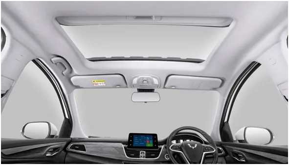
Sunroofs can be opened and closed using an electronic system. Sunroofs cars allow light, fresh air, or even both to enter the car cabin. It’s easier to imagine sunroof as a window on the car roof.Commonly, sunroofs carry two types of panels made from the same solid metal used for the car ceiling exterior and can be pulled by hand to open the glass panel. Above it is colored glass which can be tilted backward to allow air from outside to enter the cabin.
Moonroof
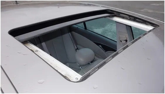
Moonroofs are actually one type of sunroofs. However, the material and uses are different. Moonroofs are made to allow the car driver and passengers to enjoy the outside view at night without having to get out of the car or open the car roof. Moonroofs have colored glass panels that allow light and air to enter without having to shift the visor. However, lately, moonroofs are also equipped with a metal coating to keep the sunlight from entering directly into the cabin during the day. Usually, the moonroof opens just slightly compared to the sunroof, so that air and light can enter into the cabin. However, there are a number of car manufacturers who now make moonroofs wide open just like sunroofs. The working systems between moonroofs and sunroofs are also slightly different. Sunroofs will open outwards when activated, while moonroofs will open backward into the car roof. Up until now, there is no standards to differentiate between sunroofs and moonroofs. For information, in the 80s, the sunroofs were only coated with metal and did not have a glass.
Panoramic roof
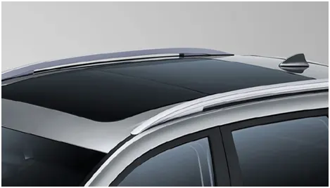
In the last couple of years, the different kind of roofs, namely panoramic roofs is embedded in luxurious cars. Recently, the panoramic roofs have become increasingly popular in premium SUV's. This type of car roof is generally similar to the moonroofs, which has a large glass panel stretching across the roof, right above the first to the second rows. The panoramic roofs can open wider compared to the moonroofs in general. Panoramic roofs also have coating blinds to keep the cabin cool when the glass layer is closed, but the view in the sky is still visible. The panoramic roofs offer a different look to the car’s interior so that it becomes more luxurious. You can see the interior of the Wuling Almaz, which has been equipped with this sophisticated feature that makes for an elegant and classy look. Not to mention that you can see the scenery during the day and night without the need to open the roof of the car.
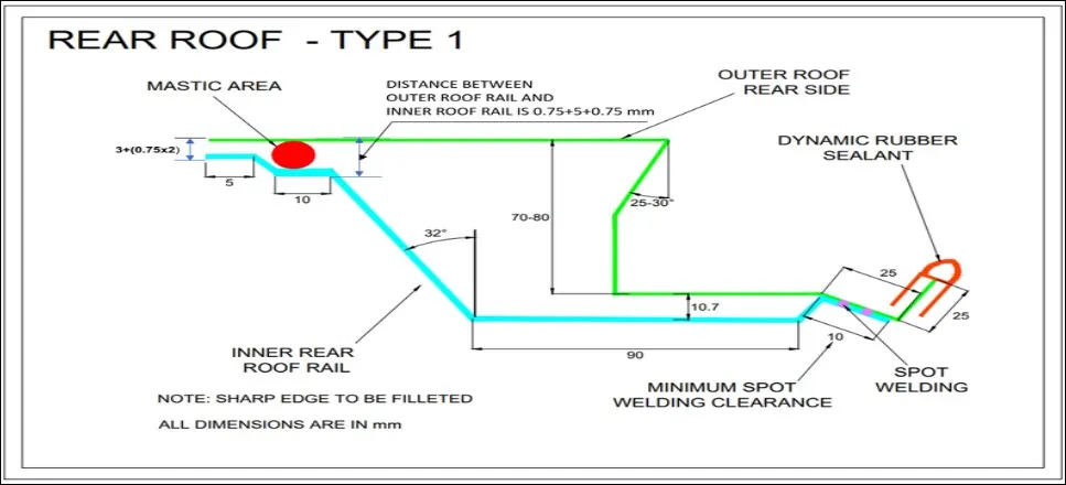
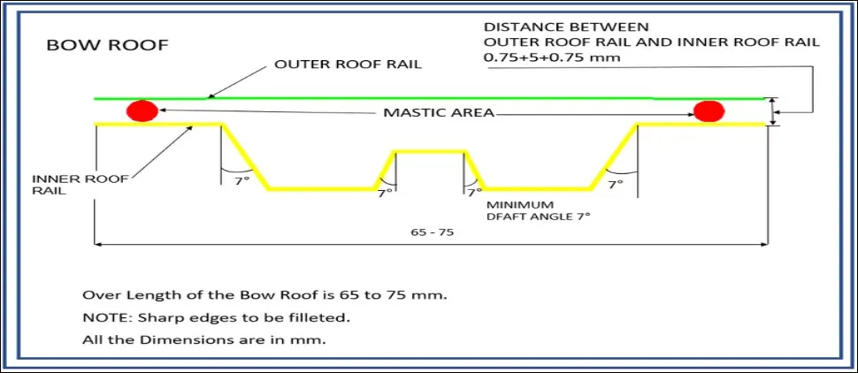
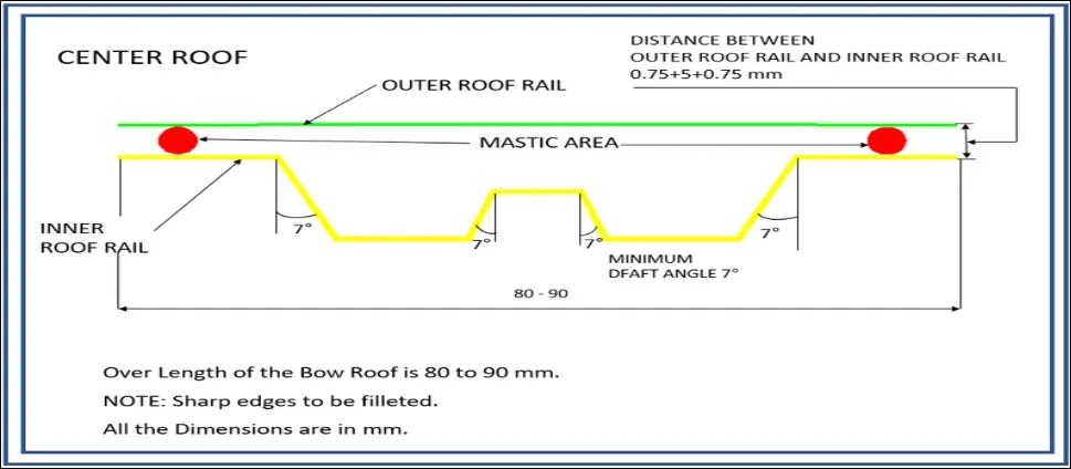
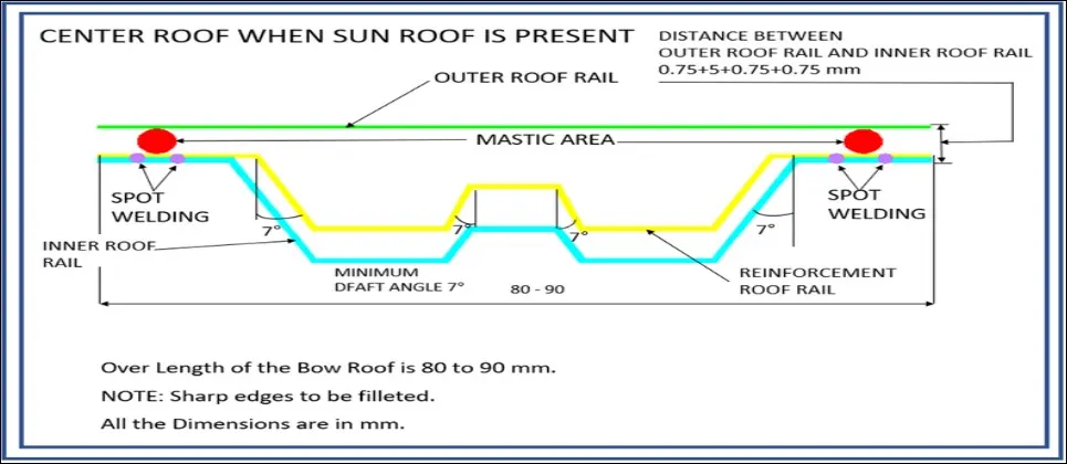
Master Section and its Parameters:
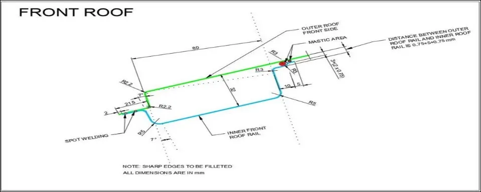
REINFORCEMENTS:-
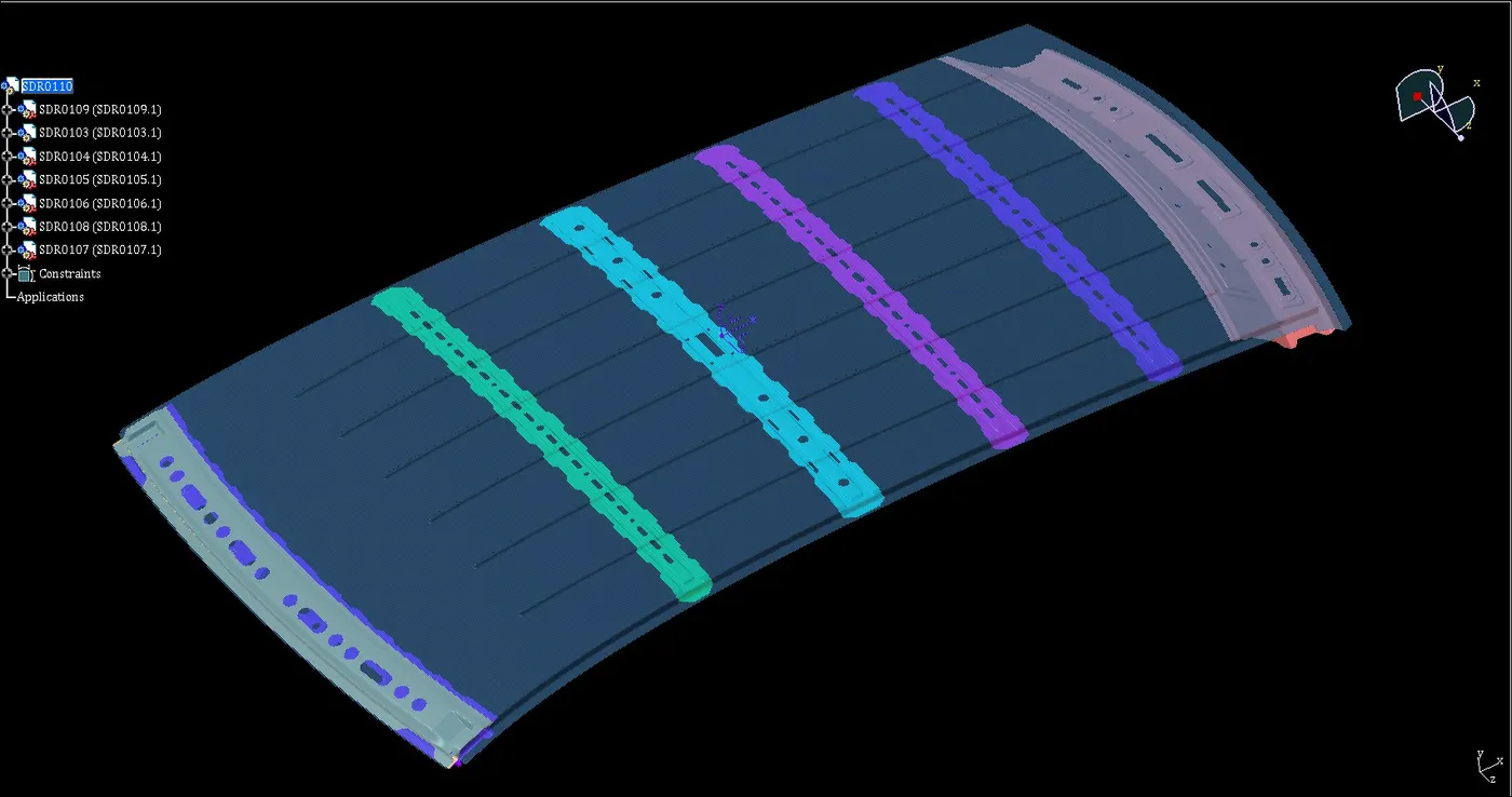
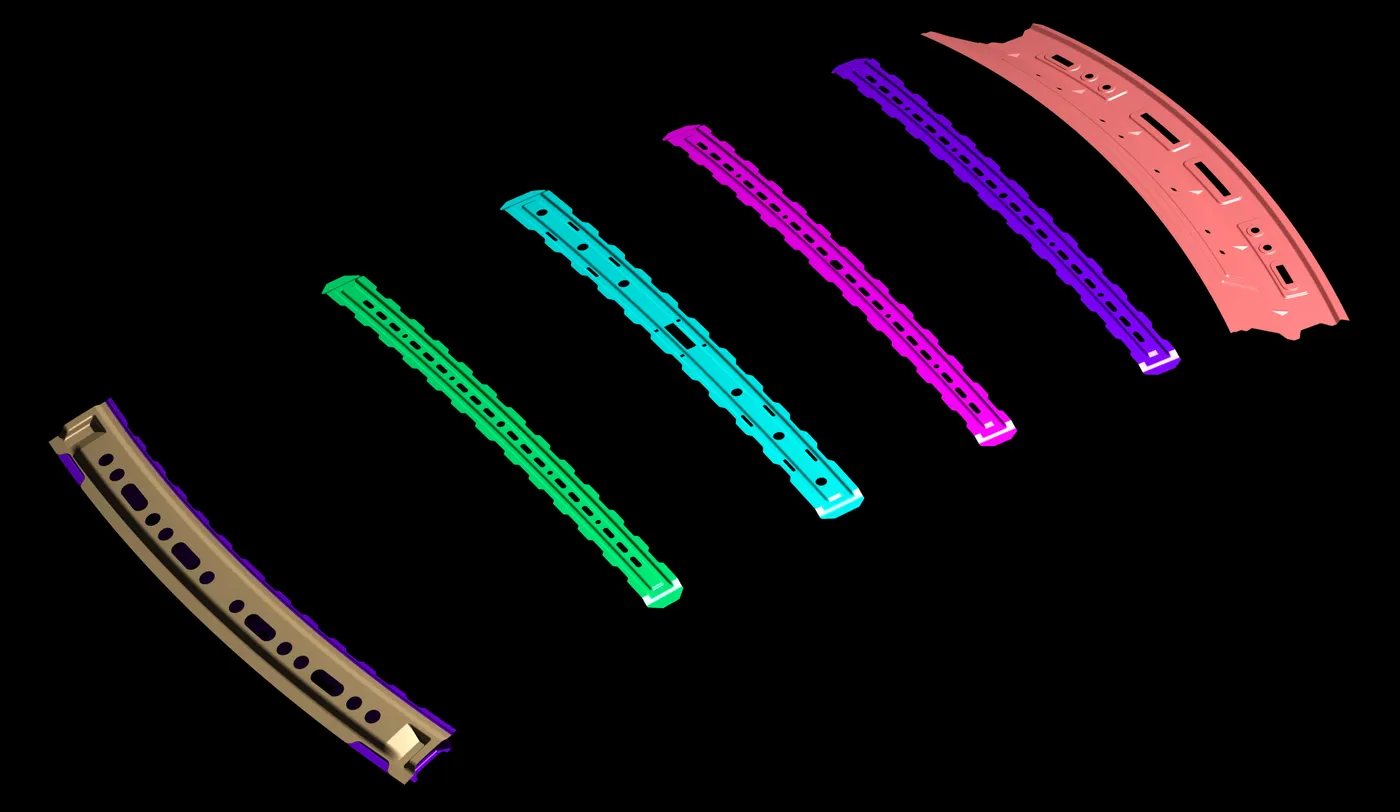
First we try to understand that when we get a piece of sheet metal, it tends to be soft and weak, and can be bent easily comparing with the metal blocks. But if it is so weak, why product developers are still applying the sheet metal to the auto parts, or design it into enclosure, housing, bracket and much more? The fact is the sheet metal parts can be strengthened accordingly, so that they can play their roles in different applications. The flat sheet metal part is not strong enough, as it lacks of the structural integrity. In addition, the flat sheet metal part is easy to bend and deform under pressure. Therefore, the flat sheet metal design should be avoided. Adding ribs, flanges, or hems to sheet metal parts are suggested to bolster the sheet metal parts. If the roof is flat, it is weak and cannot able to with stand the external load like snow load, roll over and etc. so in order to increase the strength of the roof, reinforcement like front roof rail, central roof rail, rear roof rail and the bow roof rail are attached with the flat surface of the roof with different joining process. In general, there are four types of reinforcement are used,
- FRONT ROOF RAIL
- REAR ROOF RAIL
- CENTER ROOF RAIL
- BOW ROOF RAIL
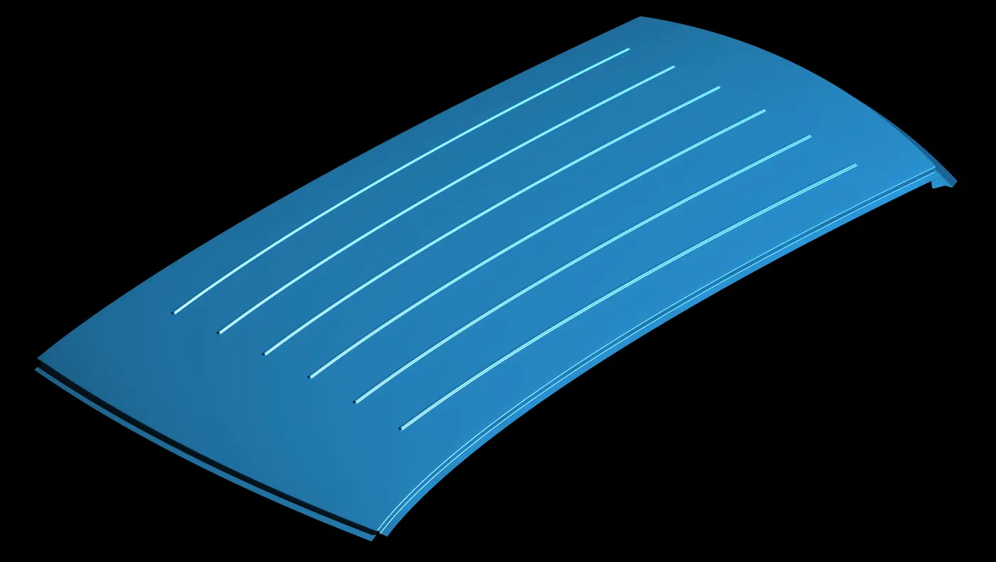
ROOF IMAGE
FRONT ROOF RAIL
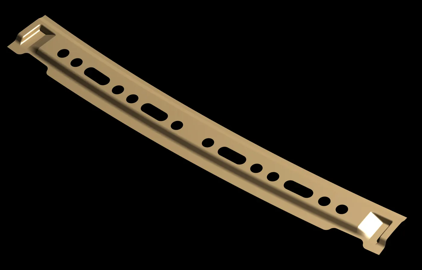
Front Inner Roof Rail
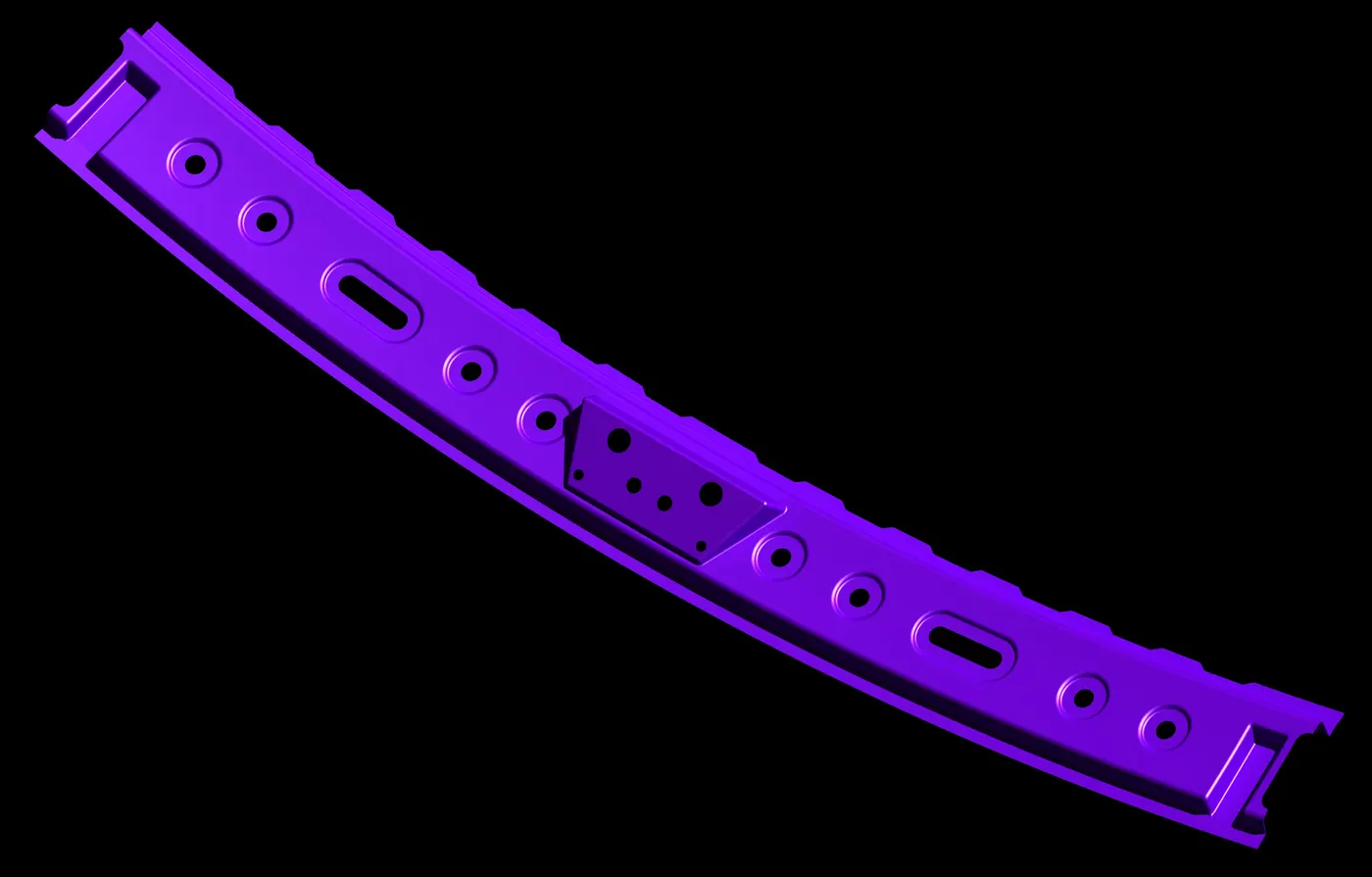
Front Outer Roof Rail
REAR ROOF RAIL
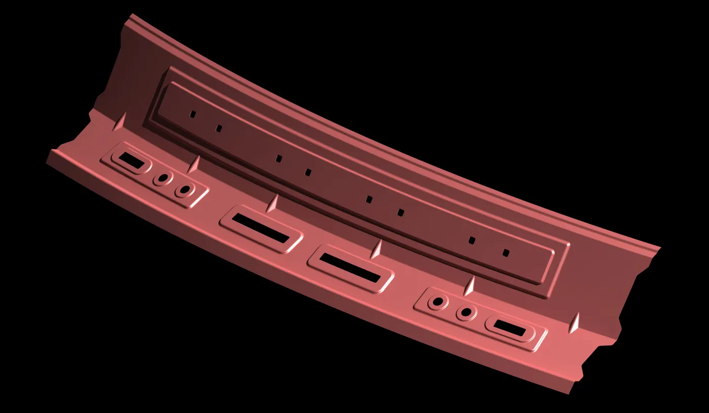
CENTER ROOF RAIL
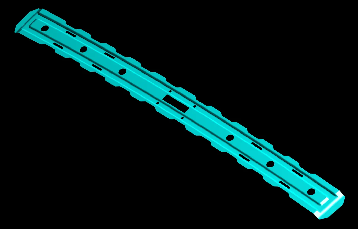
BOW ROOF RAIL
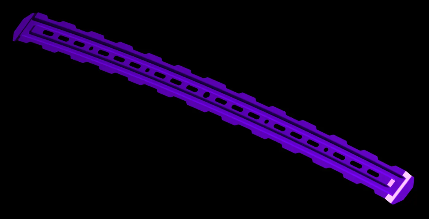
Bow Roof Rail 01
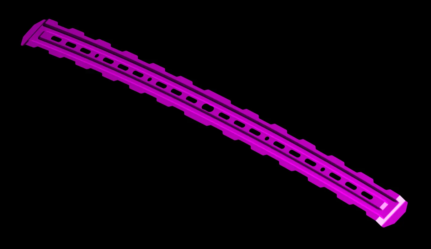
Bow Roof Rail 02
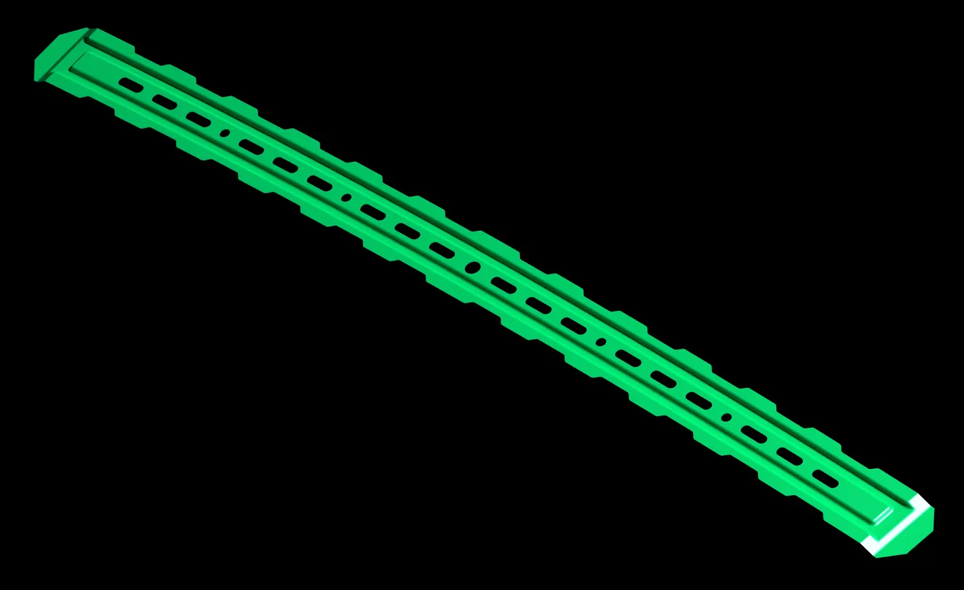
Bow Roof Rail 03
VIEWS OF COMPLETE ROOF DESIGN
SECTION MODULUS:
Section modulus is a geometric property for a given cross-section used in the design of beams or flexural members. Other geometric properties used in design include area for tension and shear, radius of gyration for compression, and second moment of area and polar second moment of area for stiffness. Any relationship between these properties is highly dependent on the shape. There are two types of section modulus, the elastic section modulus (S) and the plastic section modulus (Z).
Elastic section modulus
For general design, the elastic section modulus is used, applicable up to the yield point for most metals and other common materials.
The elastic section modulus is defined as S = I / c, where I is the second moment of area (or area moment of inertia, not to be confused with moment of inertia) and c is the distance from the neutral axis to the most extreme fiber. It is often used to determine the yield moment (My) such that My = S ⋅ σy, where σy is the yield strength of the material.
- It is the ration of moment of inertia and the distance of the topmost or the bottommost fiber from the neutral axis.
- It represents the strength of the section.
- Greater the value of S, greater will be the strength of the section.
Section Modulus, S = I (Moment of Inertia) / y
Plastic Surgery Modulus
The plastic section modulus is used for materials where elastic yielding is acceptable and plastic behavior is assumed to be an acceptable limit. Designs generally strive to ultimately remain below the plastic limit to avoid permanent deformations, often comparing the plastic capacity against amplified forces or stresses.
The plastic section modulus depends on the location of the plastic neutral axis (PNA).The PNA is defined as the axis that splits the cross section such that the compression force from the area in compression equals the tension force from the area in tension. So, for sections with constant, and equal compressive and tensile yielding stress, the area above and below the PNA will be equal, but for composite sections, this is not necessarily the case.
The plastic section modulus is the sum of the areas of the cross section on each side of the PNA (which may or may not be equal) multiplied by the distance from the local centroids of the two areas to the PNA:
��=����+����
The Plastic Section Modulus is not the First moment of area. Both relate to the calculation of the centroid, but Plastic Section Modulus is the Sum of all areas on both sides of PNA (Plastic Neutral Axis) and multiplied with the distances from the centroid of the corresponding areas to the centroid of the cross section, while the First moment of area is calculated based on either side of the "considering point" of the cross section and it is different along the cross section and depends on the point of consideration.
IN FIRST ITERATION:-
MOI (Max.) = 1.333831454e+09[mm^4]
MOI (Min.) = 4.719270266e+06[mm^4]
Length= 2108.949mm [∴Total length at the cross section area]
Let,
Y= L/2 [∴Distance between the neutral axis and the extreme end of the object]
Y= 2108.949/2
Y= 1,054.4745mm
As we know that,
Section Modulus, S = I / y
S1 = Imin. / y
S1 = 4.719270266 x 10+06/ 1,054.4745mm
S1 = (4.47547121 x 10-3) x 10+06
S1 = 0.004475 x 10+06 mm3
IN SECOND ITERATION:-
As we have the information that greater the value of S, greater will be the strength of the section. So, as to obtain the increase in strength of the section, we increase the cross section area and achieved the best result for the section modulus.
MOI (Max.) = 1.353292996e+09[mm^4]
MOI (Min.) = 4.767816936e+06[mm^4]
Length= 2108.949mm [∴Total length at the cross section area]
Let,
Y= L/2 [∴Distance between the neutral axis and the extreme end of the object]
Y= 2108.949/2
Y= 1,054.4745mm
As we know that,
Section Modulus, Z = I / y
S2 = Imin. / y
S2 = 4.767816936 x 10+06 / 1,054.4745mm
S2 = (4.521509943 x 10-3) x 10+06
S2 = 0.004521 x 10+06 mm3
Thus, it verifies that the second iteration has better result than the first iteration. After comparing section modulus of both the iteration’s, it proves that the S2 is greater than S1.
CONCLUSION
As the cross-section area is increased by offsetting the curve 0.5mm, then as a result it can be seen that there is an increase in moment of inertia and as moment of inertia increases it increases the value of Section Modulus. Thus strength of the component or part increases. As with the single attempt of analysis, a better result can’t be obtain. After having an end numbers of attempt, analization and observation on a particular component or part, the satisfying or required result needed in the design of a component is achieved.