Roof Design
Objective:
- To develop the essential flanges and reinforcements using roof styling as input.
- To do a curvature study on the roof and perform calculations to determine the position of the Bow-roof.
- To determine the Heat Distortion Criteria of the car's roof.
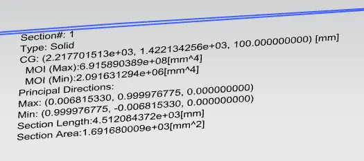
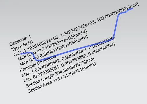
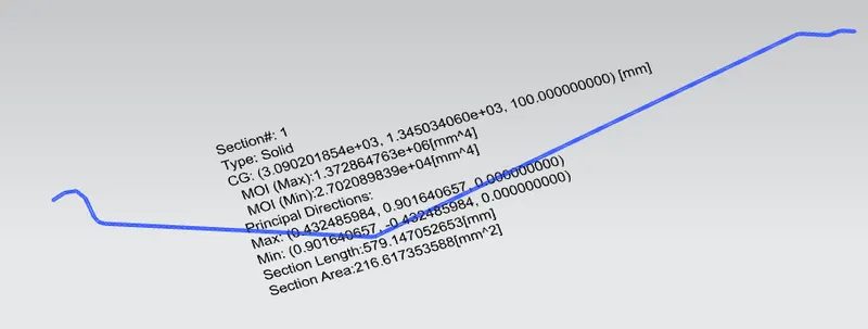
- To find the section modulus on the O-Y section of the roof and also for all the components of it.
- To determine the Snow Load Criteria for a car's roof.
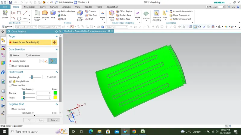
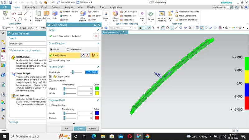
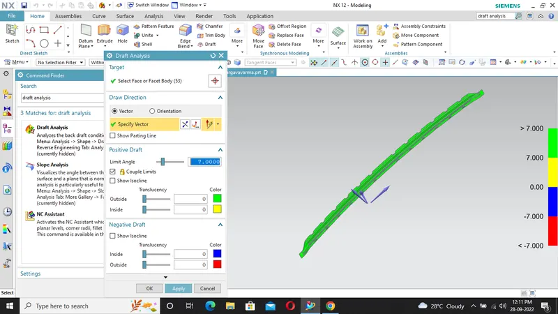
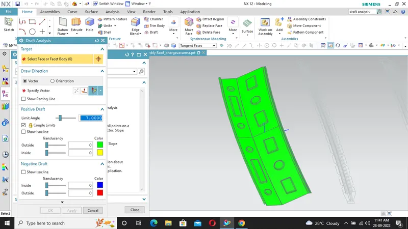
- To perform Draft Analysis on the final CAD model of the roof.
DESIGN CONSIDERATION:
- VISIBILITY CRITERIA
- HEAD CLEARENCE
- CURVATURE STUDY
- HEAT DISTORTION AND SNOW LOAD CRITERIA
- MATERIAL THICKNESS
ROOF:
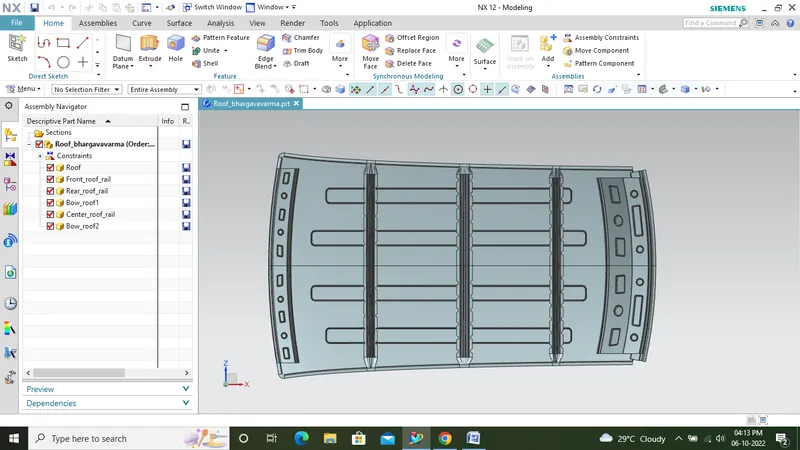
An automobile roof or car top is the portion of an automobile that sits above the Passenger compartment, protecting the vehicle occupants from sun, wind, rain, and other external elements. Because the earliest automobiles were designed in an era of horse-drawn carriages, early automobile roofs used similar materials and designs.The Automobile roof consists of the following parts:
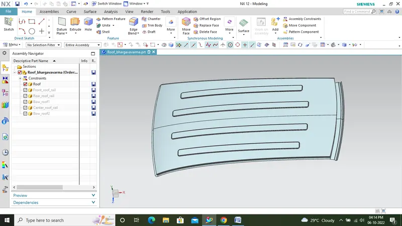
- The outer panel
- Front roof Rail
- Bow Roof
- Centre Roof Rail
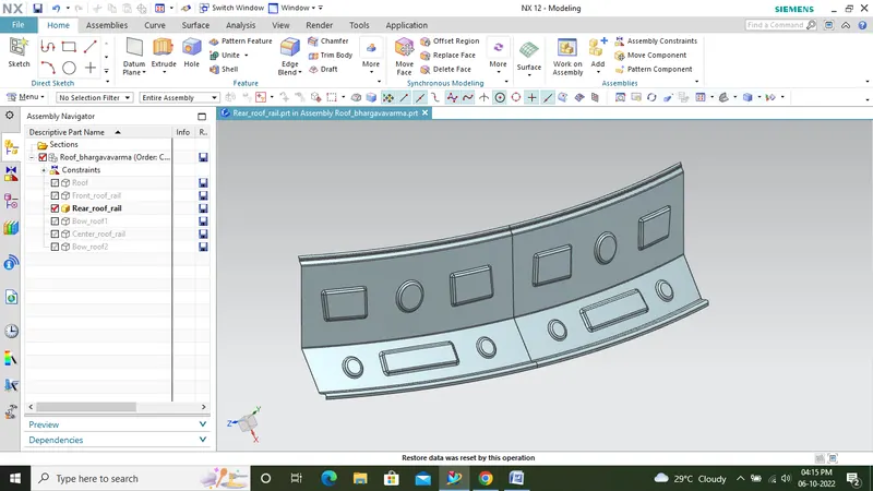
- Rear Roof Rail
The outer panel:
Front roof rail:
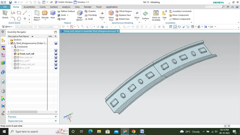
The front roof rail is created at the front side of the roof to provide strength to the roof. Headroom clearance and the driver visibility are the two important factors to be considered while designing the front roof rail. the front roof rail is connected to the roof outer panel with the help of mastic seal.
Bow roof 1:
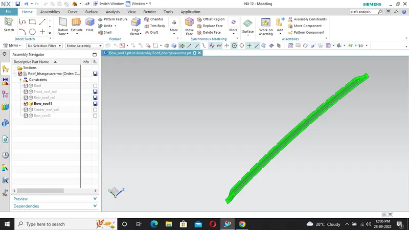
It is used to give strength to the area between the front roof and the centre roof rail. Also it is created in the area between the centre roof rail and the rear roof rail to provide enough strength. It can be created in any numbers depending upon the roof length but the position of the bow roofs is to be justified by curvature study.

Center roof rail:
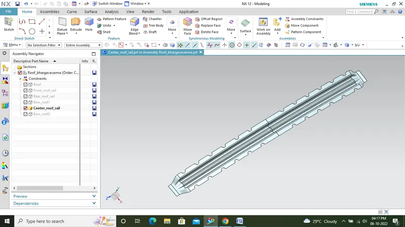
It is created at the centre of the roof. It is connected to the roof by mastic seal.
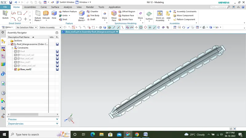
Bow roof 2:
It is used to give strength to the area between the centre roof rail and rear roof rail.It can be created in any numbers depending upon the roof length but the position of the bow roofs is to be justified by curvature study.
Rear roof rail:
Curvature Study
To satisfy heat distortion and snow load performance of the roof, we have to determine the desired optimum location of bow roofs and roof plate thickness. If the roof is exposed to high temperatures for a long time the roof structure will tend to deform. This study will help to check whether our design is valid and if not will help to determine the optimum position of the rails to avoid the deformation of the roof. Similarly if the roof is subjected to the heavy load of snow, it will tend to deform or fail. To improve the strength under the snowed condition we have to position the rails at desired specific locations.
Heat distortion study:
This study is done to check how the sheet metal components perform in the extreme heat conditions. Sheet metals have tendency to change its shape in high temperatures. To avoid any failure of sheet metal components this study is done to determine its capacity.
Bow – roof prediction Formula
W = [1.73 x 10^ (-3) x L] + [1.85 x 10^(-8) x (R^2)/t] + [ 1.10x10^(-3) x l] - 2.68
Judgement Condition: OK< 2.7> 3.1
Where,
L = Roof Length in X-Direction[mm](Roof dimension in 0-Y)
R = Roof curvature
R = 2(Rx*Ry)/(Rx+Ry)
Rx = X curvature
Ry = Y curvature
t = Roof plate thickness [mm]
l = Bow Roof Span [mm]
| Bow–Roof Prediction calculation (w) | ||||||||||
| L | Rx | Ry | R | t | l | W | Status | |||
| front roof rail - bow roof1 | 2043.8527 | 5733.129 | 2647.359 | 3622.140061 | 0.74 | 382.9436 | 1.6051006 | OK | ||
| bow roof1 - Center roof rail | 2043.8527 | 4900.4671 | 6486.0519 | 5582.862321 | 0.74 | 433 | 2.111374 | OK | ||
| Center roof rail - Bow roof roof2 | 2043.8527 | 3918.5323 | 10883.924 | 5762.423057 | 0.74 | 426 | 2.1546032 | OK | ||
| bow roof rail 2 - Rear roof rail | 2043.8527 | 3314.59235 | 14362.55 | 5386.164507 | 0.74 | 218.9558 | 1.8219858 | OK | ||
Snow load Prediction formula
Qr = [Iy x t2] / [α x s x [(Rx + Ry)/2]2 x 10-8]
Where,
α = My x Lx^2 x 10^-12, My = Y(Ly-Y)
Judgement condition = Qr ≥ 3.1
250 ≤ s ≤ 380
t = Roof plate thickness [mm]
Ly = Distance between the front and rear roof Rails on the Vehicle along with 0Y[mm]
Length of Roof panel with the center point between Roof rail Front /Rear as the reference point of the front and the rear.
Lx = Distance between the Left and Right end of the roof on the Roof BOW [mm]
Width of the roof panel exposed on the surface.
Y = Distance front Front Roof Rail to Roof BOW[mm]
s = Distance for which Roof BOW bears divided load [mm]
s = L1/2 + L2/2
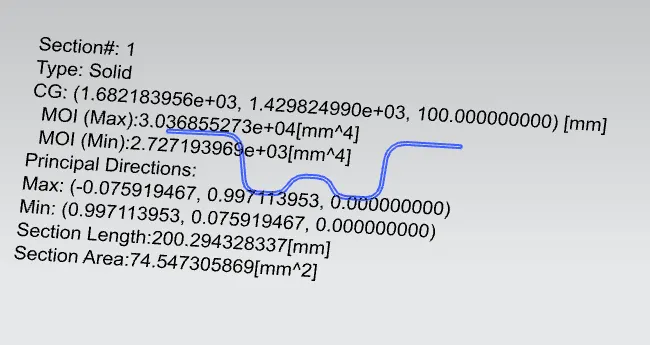
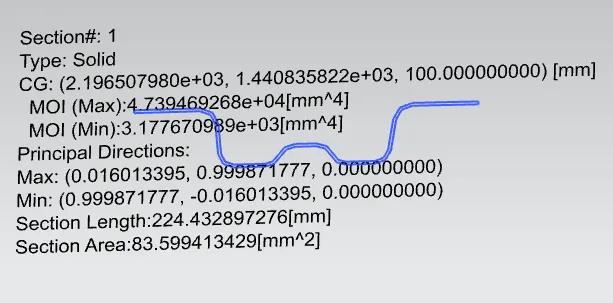
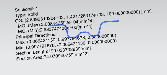
Iy = Geometrical moment of inertia of Roof BOW (Y cross-section) [mm4]
Rx = Lateral direction curvature radius of roof panel Y cross-section on Roof BOW [mm]
Roof panel curvature Radius of the Length Lx in Front view
Ry = Longitudinal Direction curvature radius of the Roof panel X cross-section on Roof BOW [mm]
Roof panel X curvature radius of length s in Side view
| Snow Load calculation(Qr) | |||||||||||||||
| Rx | Ry | Lx | Ly | L1 | L2 | Y | My | S | α | T | Iy | Qr | Status | ||
| front roof rail - bow roof1 | 4058.3021 | 4729.2193 | 1137.38 | 2043.8527 | 495.068 | 514.245 | 495.068 | 766753.74 | 504.6565 | 0.991898 | 0.75 | 2727 | 15.87347 | ok | |
| bow roof1 - Center roof rail | 4299.7299 | 80710.65439 | 1087.5209 | 2043.8527 | 514.245 | 502.6078 | 1009.5925 | 1044181.3 | 508.4264 | 1.234955 | 0.75 | 3177.671 | 0.157568 | NG | |
| Center roof rail - Bow roof roof2 | 8731.5932 | 6405.76238 | 1058.769 | 2043.8527 | 502.6078 | 407.4084 | 1512.2003 | 803964.92 | 455.0081 | 0.901238 | 0.75 | 2683.7 | 6.426253 | ok | |
| bow roof rail 2 - Rear roof rail | 3314.59235 | 14362.55 | 1046.4025 | 2043.8527 | 407.4084 | 0 | 1919.6087 | 238499.86 | 203.7042 | 0.261147 | 0.75 | 0 | 0 | nil | |
Manufacturing technique:
The manufacturing process for car roof parts, comprises the following steps:
By outer board machining process, bar shaped assembly, ring-shaped component processing and roof cant rail processing technology, formed respectively;
Outside plate process: the first step, open straight snips plate: first select applicable cold coiling specification, cold coiling is opened flat; Then according to production material specification, will open cold coiling after flat and be cut into into the iron plate of corresponding size; Finally the iron plate after shear is cleaned to iron filings; The first step, oil pressure, punch press: first iron plate is extended; Secondly to its trimming and punching; Then to its flanging and punching; Finally, after punching completes, it is carried out to the operation of side folding; Completed the making of outside plate;
Bar shaped assembly and ring-shaped component process: the first step, blanking, stamps out iron plate the outline blank of many roof cant rails, a ring-shaped component and a bar shaped assembly; Second step, carries out annular punching to ring-shaped component; Bar shaped assembly and roof cant rail are carried out to bar shaped punching;
Car roof anabolic process: the first step, by a plurality of M6 nuts of a side spot welding of ring-shaped component; By two M6 nuts of bar shaped assembly two ends spot welding; Second step, spots weld bar shaped assembly the opposite side of the corresponding nut of ring-shaped component; And circular groups and the punching of bar shaped assembly are aimed at; The 3rd step, is welded to ring-shaped component the inner side of outside plate; The 4th step, spots weld roof cant rail the inner side of outside plate; Finally car roof integral body is carried out to sanding thorn and ending.
Conclusion:
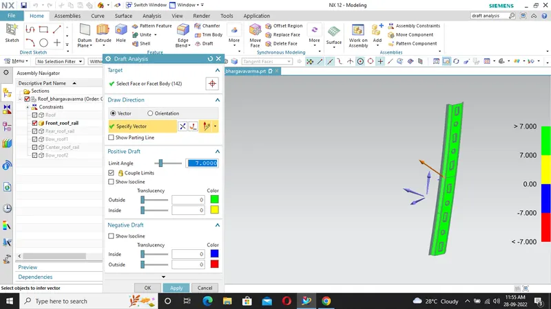
Design of roof was done using NX cad Draft analysis was done, Moment of inertia is calculated and checked for heat load and snow load criteria. Design passed the heat load criteria but failed at one sections in snow load criteria. To overcome this, embosses are provided on the roof surface.