Roof Crush Analysis of Dodge Neon
DODGE NEON ROOF IMPACT TEST:
Objective: To simulate the roof crush or roof impact analysis of the Dodge Neon model using 'CAE'. This project was done to analyze the deformation, stresses, and strains produced in the vehicle during a roof impact analysis.
Introduction:
- A crash test is usually done to analyze the vehicle beforehand and make some changes in the body, structure, or material of the BIW if required. Different types of crash tests are performed on a vehicle like a frontal crash, side crash, roof crush, pedestrian impact, etc. to ensure the safety of the passengers as well as the pedestrian.
- The data obtained from the crash testing is usually in terms of forces, stresses, displacements, curves, etc. which can be analyzed and the safety of the occupants can be predicted. The simulations done in the software are very much closer to the actual crashing scenario of a vehicle.
- In this project, the Dodge Neon 2005 model was tested for the roof crush analysis. For this, an impactor was placed on top of the vehicle at a certain angle (specified below) and was crushed on the roof.
- This project was done in HyperMesh and HyperCrash for case setup and simulation, and for the post-processing and 'FEA', HyperView and HyperGraph 2D was used. Different types of energies, Von-Misses stresses, plastic strains, displacements, and force graphs were computed.
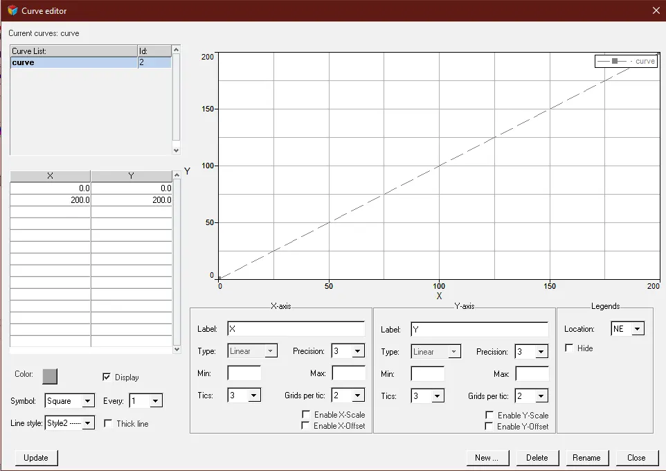
- The impactor is a rigid body with only one DoF in the translational Z-direction whose displacement was set to be 200mm till the end of the simulation. The increment of the displacement and velocity was linear, starting from 0mm/ms at t=0.
Procedure:
- There were two separate components provided, car model and the impactor. The impactor had to be aligned with the roof of the car as per the specifications in the Federal Motor Vehicle Safety Standards 216 (FMVSS 216).
- Both the models of the car and impactor provided in the .rad format were imported using the ‘import solver deck’ option in “HYPERMESH”. The impactor had to be aligned exactly on the roof frame of the car as per the coordinates provided.
- For this, ‘translate’ and ‘rotate’ commands were used. The impactor was first translated in X-axis in such a way that the target point on the car and the master node of the rigid body of the impactor were co-linear. Later it was translated similarly in the Y and Z axis such that it came right on top of the target point on the car frame.
- Later as per the guidelines provided in the question, the impactor was rotated. The following rotations were followed:
- A 180° rotation about the global z-axis
• A 5° rotation about the axis through axis AB
• A 25° rotation about the axis through axis AC
• A translation to put point A at global (-3500.00, 584.822, 1343.06)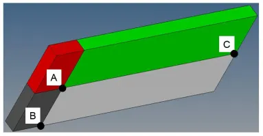
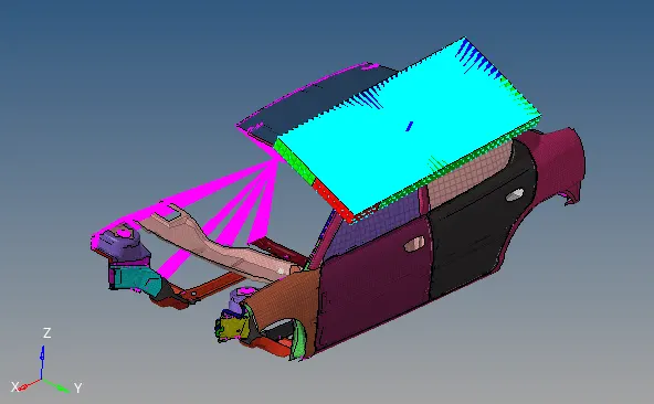
- For this operation, the ‘rotate’ option under the ‘tools’ tab in HyperMesh was used. The image shows the final position of the impactor according to the standards.
Interfaces:
- After positioning the impactor, the interfaces were added between the car and the impactor. All the interfaces present in the model were deleted and two new ‘TYPE7’ (/INTER/TYPE7) interfaces were created.
- One of the interfaces was for the car model. In that, all the properties were set as the reference or the ideal properties, and the slave nodes and the master segments were both set as the nodes of the car itself.
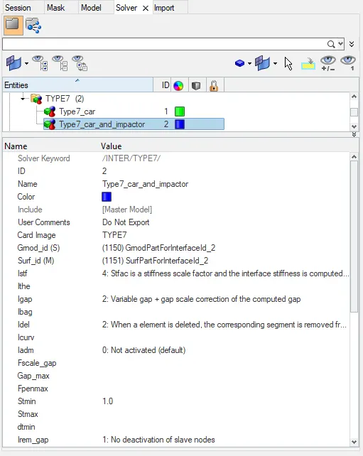
- The second interface was created between the car and the impactor. All of its other parameters were kept as the reference values. The friction value ‘FRIC’ was set as 0.2, with a minimum gap of 0.5mm. The slave nodes were selected as those of the car, while the nodes of the impactor were set as the master nodes. The image below shows the TYPE 7 interface created for the car and the impactor. These interfaces were added in the time history file ‘TH’ by ‘Solver>TH>create new>Entity ID>INTER’.
Boundary Conditions:
- During a roof impact test, the vehicle is fixed underneath using hooks or other systems. It is not supposed to move downward when the impactor hits the vehicle since it would reduce the accuracy of the results. Therefore, to get a realistic condition and to restrict the vehicle from moving downward (Z-axis), some boundary conditions had to be set.
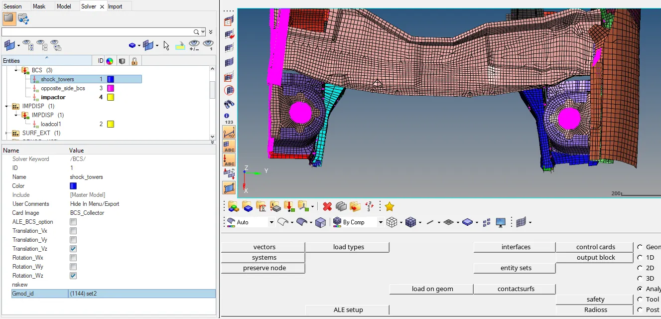
- Since suspension and wheels are the only links between the vehicle body and ground, the boundary conditions were applied at the point where the shock towers or the shock absorbers are connected to the frame of the vehicle.
- This was done by creating a rigid body from the ‘1D’ option getting its master node at the center of the rigid body. At this master node, the boundary condition had to be applied. A ‘BCS’ card was created from the ‘solver>create>boundary conditions>BCS’. The translational and rotational Z-axes were checked to arrest the degree of freedom in that direction. This operation was done for all the three shock towers keeping the skew or the frame of reference as the global coordinate system. The image below shows the boundary conditions created at the three shock towers in the model.
Impactor Boundary Conditions:
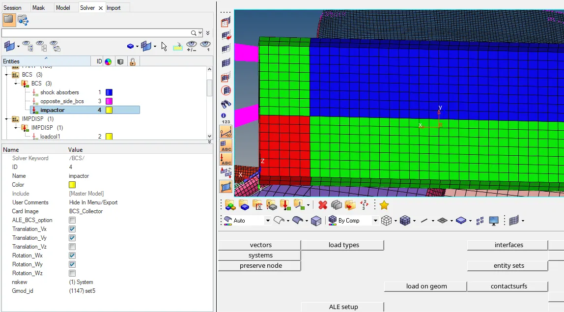
- The impactor was supposed to move only towards the roof of the vehicle to get the right impact. Therefore a boundary condition was created on the free node of the spring present on the impactor. The same procedure as above was followed for creating this boundary condition named ‘impactor’.
- A moving skew was created on the impactor in such a way that its Z-axis is facing the roof of the vehicle. This skew was mentioned in the ‘nskew’ option of the BCS card. Since the motion of the impactor had to be allowed only in the translational Z-axis (according to the skew created), all the other DOFs were checked to restrict the motion in those directions. The image below shows the BCS card created for the impactor.
- Since in this project, partial model of the vehicle consisting only the middle portion frame and the doors on the driver’s side is being used, there would be some movement and abrupt deformation during simulation due to the unbalanced masses.
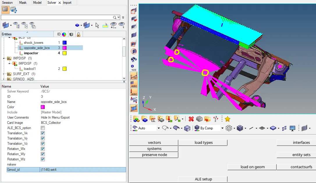
- To avoid the movement of the opposite side and to get accurate results, a boundary condition was created on three points. One on the master node of the rigid body representing the remaining components and masses of the car, and the other two on the rear cross-rails.
- In this BCS card, all the DoFs were arrested to restrict the motion of the vehicle in any direction, and the skew was set as a global system. The image below shows the BCS card with the circled master nodes.
Imposed Displacement:
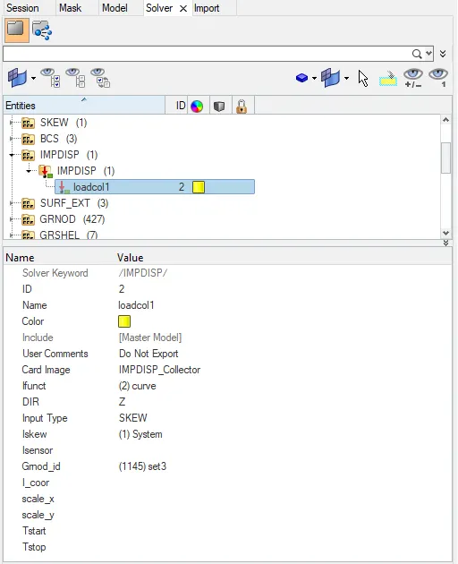
- To move the impactor towards the vehicle continuously until the end of the simulation, a displacement had to be imposed on it. For this, an ‘IMP DISP’ card was created from the ‘solver>create new> boundary conditions>IMPDISP’.
- The function for this imposed displacement card was a linear function, starting at t=0 with 0mm displacement till t=200 with the complete 200mm displacement. For the frame of reference, the skew which was created on the impactor before was selected, and the direction of the imposed displacement was set as Z. The image below shows the IMPDISP curve and card created on the impactor.
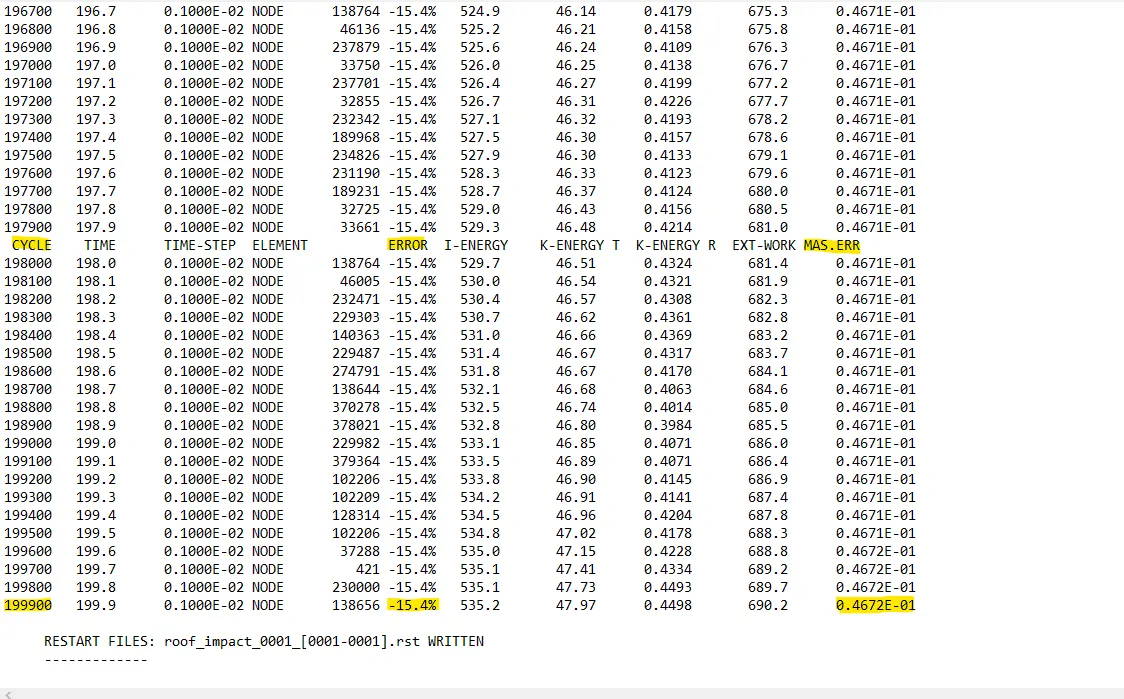
- After setting up the relevant boundary conditions and all the other cases, the simulation was started. For this purpose, the ‘RADIOSS’ operation was used from the ‘analysis’ tab. ‘-nt 4’ was used in the ‘options’ area for multi-threading purposes. The simulation took around 11300 seconds. After completing the simulation, 0001.out file i.e. the engine out file was analyzed for the cycles, energy error, and mass error.
Cycles: 199900
Energy Error: -15.4%
Mass Error: 0.04672
- The mass error of 46 grams was well within the limit of 2% of the total mass of the model. Though the energy error in the model was very high, it was somewhat acceptable as it was a quasi-static analysis and may have been created due to under integrated elements and hourglass energy.
Output Requests:
- Following outputs had to be requested in the ‘RADIOSS’ before the simulation:
- Elemental Energy
- Elemental Equivalent Plastic Strain
- Elemental Hourglass Energy
- Elemental Von-Misses Stress
- Nodal Added Mass
- Turn on parallel arithmetic
Displacement:
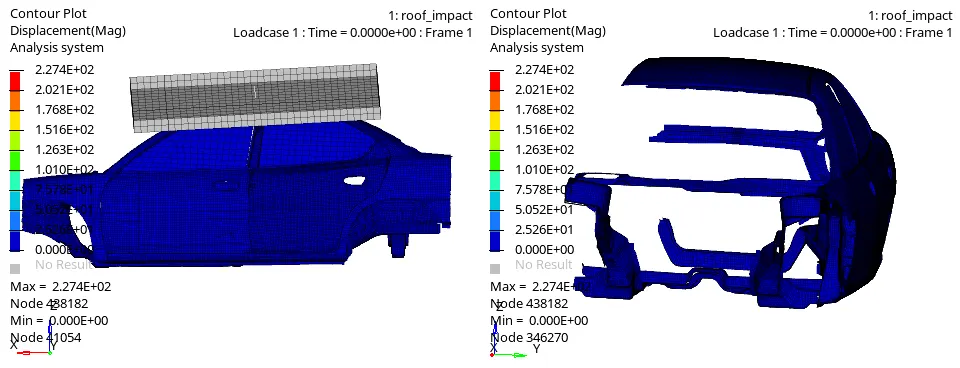
- The largest displacement recorded in the model was around 227.4mm 4881822nd node. The animation below shows the displacement in the model.
Von-Misses Stress:
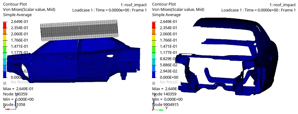
- The Von-Misses stress induced in the model throughout the simulation was 0.2649 KN/mm2 as seen in the gif below.
Plastic Strain:
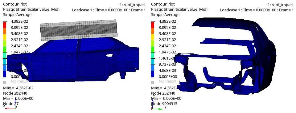
- The amount of plastic strain in the model was very low with a value of around 0.00438 with the use of a simple averaging method.
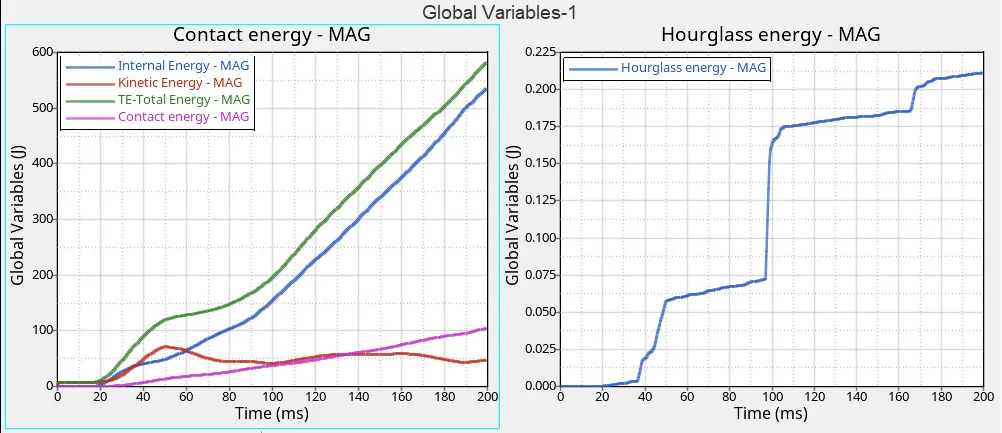
- Later in the HyperGraph 2D, the graphs for internal energy, kinetic energy, contact energy, and hourglass energy, and the force v/s displacement were plotted.
Energy Plots:
- The approximate amount of energies generated by the end of the simulation are as follow:
Internal Energy: 530J
Kinetic Energy: 50J
Contact Energy: 100J
Hourglass Energy: 2125J
Parallel Arithmetic/Cross Plot:
- The cross-plot is a chart that compares multiple measurements made at a single time or location along two or more axes. From the HyperView, the ‘build plots’ option was selected, and a displacement v/s time graph was plotted.
- Later by changing the HyperView window to HyperGraph 2D, the total resultant force v/s time graph of the interface between the car and the impactor was plotted. By using the ‘Math>two curves>cross plot’ option, the graph between the total resultant forces and displacement was plotted as shown below. Here the displacement of node no. 101855 has been plotted.
Result and Conclusion:
- FMVSS 216 Target Load: According to FMVSS 216 standards, the reaction force of the vehicle must be at least 47000N for a vehicle with a GVWR of 2722kg or less. This 47000N value should be equal to 3 * GVW. GVW is the Gross Vehicle Weight. It is the maximum operating weight specified by the manufacturer of the vehicle.
- In our case, the model which was analyzed for roof crush had a mass of 174.844kg. According to the formula, 3*174.844*9.81=5145.658N which is not equal to the specified value of 47000N.
- To get the 47000N value, the GVW of the vehicle must be 1600kg.
- So along with this, the project on roof impact analysis of dodge neon was completed successfully. For this project, two models were provided, one of the cars and the other of the impactor.
- The impactor was positioned on to the roof of the car according to the FMVSS216 standards and the boundary conditions were set and the RADIOSS operation was carried out. From the results, it was clear that the kinetic energy of the simulation was very low since it was a quasi-static case.
- After observing the simulation, it can be concluded that to increase the safety of the passengers, the A-pillar, and the B-pillar assembly can be reinforced which will increase the overall strength of the vehicle.