Roof Crash Analysis using Radioss in Hypermesh
AIM :
To test the vehicle crashworthiness by conducting a Roof Crush test as per Standard requirements and evaluate the results by using Radioss in Hypermesh.
OBJECTIVE :
- Import the model and transform the impactor into the required position.
- Create appropriate Interface with recommended parameters
- Create BCS to keep the suspension shock tower nodes locked in z.
- Create BCS on Impactor as per given conditions.
- To Create an Engine File and set the Timestep as per given conditions.
- To create Imposed Displacement to Impose the velocity of the impactor starting from 0 mm/s at t = 0. The displacement of the impactor should be 200 mm @ 200 ms.
- To include Selected output in animation files.
- Run the Simulation and Plot the Force vs Displacement and Energy vs Time.
SOFTWARE USED :
- Radioss (in Hypermesh)
THEORY :
FMVSS 216, Roof Crush Resistance, establishes strength requirements for the passenger compartment roof of passenger cars, multipurpose passenger vehicles, trucks, and buses with a GVWR of 2722 kilograms or less. The purpose of the standard is to reduce deaths and injuries due to the crushing of the roof into the passenger compartment in rollover accidents.
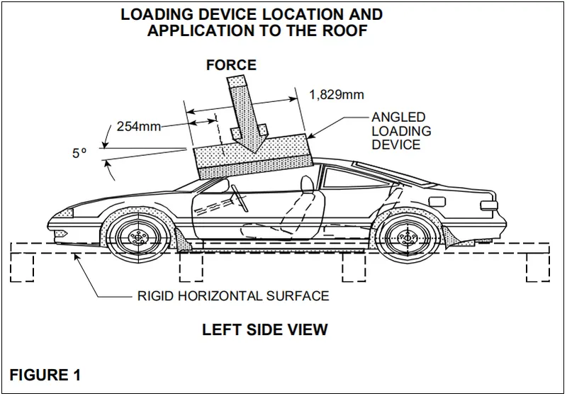
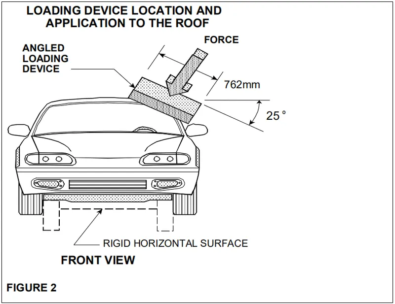
The prescribed static loading device is a rigid unyielding rectangular block 762 millimeters by 1,829 millimeters. It shall not move more than 127 millimeters to achieve the specified resistive load when applied to the forward edge of a vehicle’s roof – see Figures 1 and 2. The resistive load to be achieved is 1½ times the unloaded vehicle 2 weight (UVW) of the test vehicle or 22,240 Newtons, whichever is less.
Both the left and right front portions of the vehicle's roof structure shall be capable of meeting the requirements but a particular passenger car need NOT meet further requirements after being tested at one location. The passenger car's sills shall be placed on a rigid horizontal surface and fixed rigidly in position. The vehicle's windows shall be closed and the doors shall be locked. Any convertible top or removable roof structure shall be secured in place over the occupant compartment. Remove roof racks or other nonstructural components. The force shall be applied in a downward direction perpendicular to the lower surface of the static loading device at a rate of not more than 13 millimeters per second until reaching the compliant resistive load. The test shall be completed within 120 seconds. The static loading device shall be guided throughout the test so that it moves, without rotation, in a straight line with its lower surface oriented as follows and as shown in Figures 1 and 2.
- Its longitudinal axis is at a forward angle (side view) of 5º below the horizontal and is parallel to the vertical plane through the vehicle's longitudinal centerline.
- Its lateral axis is at a lateral outboard angle, in the front view projection, 25º below the horizontal.
- Its lower surface is tangent to the surface of the vehicle.
- The initial contact point, or center of the initial contact area, is on the longitudinal centerline of the lower surface of the static loading device and 254 millimeters from the forward most point of the centerline.
- If the vehicle being tested is a multipurpose passenger vehicle, truck, or bus that has a raised roof or altered roof, and the initial contact point of the static loading device is on the raised roof or altered roof to the rear of the roof over the front seat area, the plate is positioned so that the midpoint of the rearward edge of the lower surface of the static loading device is within 10 mm of the transverse vertical plane located at the rear of the roof over the front seat area.
Real Roof Crush tests, quasi-static or dynamic, have been widely used to evaluate the safety integration of vehicle structure, where there are specific standards such as FMVSS 208 and 216. With the development of crash technologies, several crash codes such as LS-DYNA3D, pam crash, and Radioss, are used for vehicle impact simulations. The most difficult of the simulation is still the quasi-static roof crush simulation. If a higher speed is used for the quasi-static simulation, it will result in inertia effects which smooth out non-linearities and deficiencies in the solution algorithms. While implicit solver could address quasi-static impact scenarios, the large deformation of parts surrounding roof and pillar areas, and contact involving multiple vehicle parts make the convergence of the solutions very difficult and sometimes unstable within implicit solvers.
Quasi-static Analysis :
Static analysis is when the load does not depend on time. Dynamic analysis is when the load does depend on time and inertia plays an important role.
Quasi-Static, which is time-dependent but then the load acts at a slower rate such that the inertial effects of the body are negligible. When the body is loaded slowly its deformation rate is also very slow.
PROCEDURE :
Model Import :
1. Import the neon_roof_0000 rad file and FMVSS_216_ROOF_IMPACTOR_coarse_0000 file using Radioss in Hypermesh.
Fig: Car(BIW) and Impactor
Impactor Transform :
2. Place the Impactor in a required position(Top of the Roof) as per given Conditions.
3. Isolate only the Impactor & Roof and Hide other Components.
4. Go to Tools-->rotate option and Select all nodes on the Impactor and a 180° rotation about the global z-axis with the point opposite to C as a base point and Click rotate+.

Fig: Rotation about the global z-axis
5. Change Z-axis to N1, N2, N3, B, and Select N1 as Point A, N2 as Point B, and Base Point as Point A. A 5° rotation about the axis through axis AB and Click rotate+.
6. Select N1 as Point A, N2 as Point c, and Base Point(B) as the midpoint of AC. A 5° rotation about the axis through axis AB and Click rotate+.
7. Go to Tools-->Translate option and Select all nodes on the Impactor and Select x-axis and Set magnitude value as -3500 and Click translate+.
8. A translation to put point A at global ( -3500.00, 584.822, 1343.06) and set impactor at the top of the roof by using the translate option.
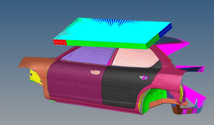
Fig: Impactor Transformed
Creating Interface :
9. Create a Type 7 contact interface between the impactor and the car and Create another Interface for the SelfContact of Car.
10. Go to Solver-->Create-->INTER-->new Type-7 Interface with recommended parameters and Select Master as Impactor and Slave as Car.
11. Create another Interface for SelfContact of Car, by selecting Master & Slave as a Car.
Fig : Type-7 Interface - Master(Impactor) & Slave (Car)
11. Choose appropriate Stiffness, Minimum Gap(Gap_min), Co-efficient of Friction, Friction Penalty Formulation, and Save data from the interface to the Time History file.
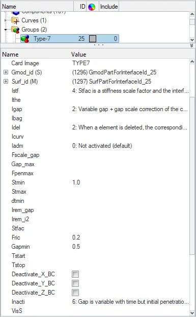
Fig: Type-7 with Recommended Parameters
Boundary Conditions for Suspension :
12. Go to 1D-->Rigids option and Select multiple nodes & Calculated node and Select edges on the Suspension shock tower and Click Create. Create RBODY for all suspension shock towers.
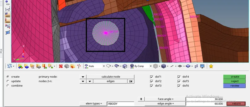
Fig: Rigid Body Created in Suspension Shock tower
13. Go to Solver-->RightClick-->Create-->Boundary Conditions-->BCS option and Select Centre node of RBODY by creating grnd_ID and Locked in Z(DOF3).
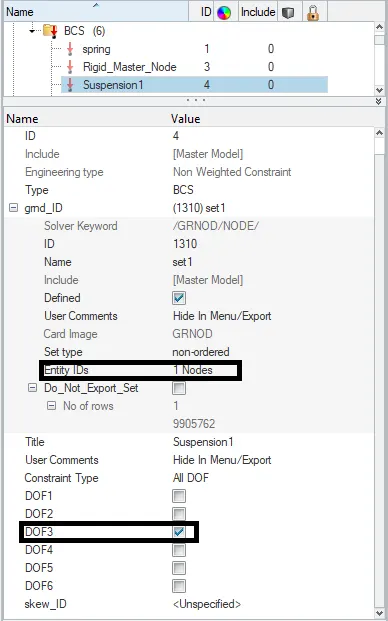
Fig: Boundary Condition for Suspension Shock Tower
Impactor Boundary Conditions :
14. The impactor assembly contains a spring attached for stability. Create a BCS collector to fix the free end of the spring.
15. Go to Solver-->BCS-->RightClick-->Create option and Select the Spring Top end of the node by creating grnd_ID and Locked in all DOF.
16. Create a moving SKEW to define the direction normal to the impactor’s face.
17. Go to Solver-->RightClick-->Create-->SKEW-->MOV option and Select origin node, Axis node, and Plane node and Click Create. Z-axis should be in the Normal direction.
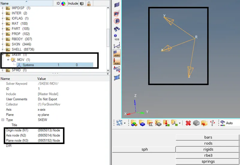
Fig: Creating Skew to define normal direction to impactor's face
18. Create a BCS collector to guide the master node of the impactor rigid body so that it is free to translate normally to the face of the impactor, but is fixed in all other DOFs.
19. Go to Solver-->BCS-->RightClick-->Create option and Select the Master node of the impactor Rigid Body by creating grnd_ID and Locked in all DOF except DOF3.
Imposed Displacement :
20. Impose the velocity of the impactor starting from 0 mm/s at t = 0. The displacement of the impactor should be 200 mm @ 200 ms. To avoid abrupt changes in the acceleration of the impactor.
21. Go to Solver--> Right Click-->Create-->Boundary Conditions-->IMPDISP option and Select the Master node of the impactor Rigid Body by creating grnd_ID and Set in Direction Z and Select the Skew ID which is already created in SKEW.
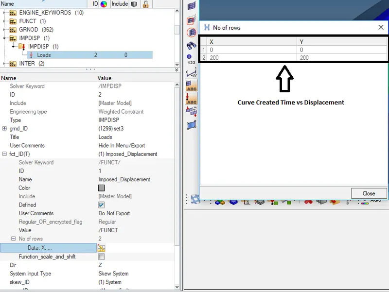
Fig: Creating Imposed Displacement
Engine File :
22. For using Constant Nodal Time Step, Go to Solver-->RightClick-->Create-->Engine Keywords-->DT-->DT/NODA optionand Set TScale=0.67 & Tmin=0.005.
23. Create TFILE in Engine Keywords and Set Time frequency=0.1 ms to Print time history every 0.0001 seconds.
24. Go to Solver-->Engine Keywords-->Create-->RUN option and Set Tstop=200ms to solve the simulation for 200ms.
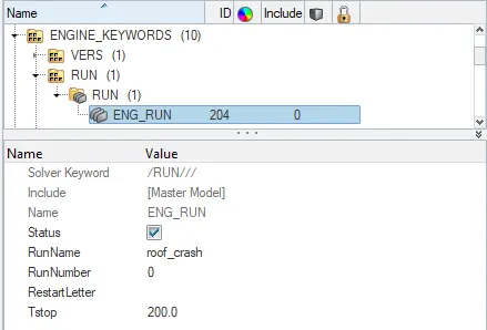
Fig: Engine File
Animation File :
25. Create an Animation file for every 0.005 seconds by using Solver-->Engine Keywords-->Create--> ANIM-->ANIM/DT option and set Tfreq=5ms.
26. Create ANIM/MASS in Engine Keywords to generate animation files containing nodal masses.
27. Create ANIM/ELEM in Engine Keywords--> ANIM option and Select the Elemental Energy, Equivalent Plastic Strain, Hourglass Energy, Vonmises Stress to include in animation files.
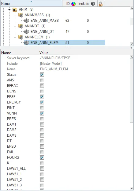
Fig : Animation File
28. Go to Model-->Cards-->AnalysisFlags-->IPARITH and turn on Parallel arithmetic.
PLOT RESULTS :
Contour Plots :
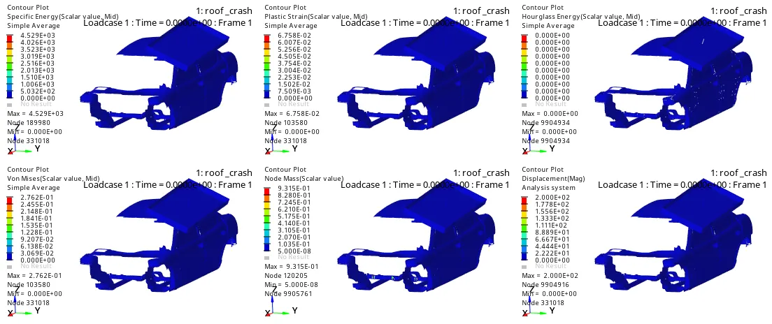
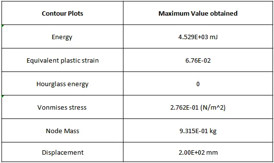
From the above contour plots observed that,
From the quasi-static roof crush simulation with the help of Hypermesh(in Hyperwiew mode) Contour plots are displayed above. From the Contour plots, accurate results will be obtained.
- A Specific Energy Plot shows the amount of energy dissipated during the roof crash and 4.529E+03 mJ is the Maximum amount of Energy dissipated.
- In Plastic Strain plot shows that the amount of deformation on the Vehicle during a roof crash. 6.758E-02 is the Maximum Strain rate.
- Hourglass energy, which is work done by the forces calculated to resist hourglass modes, takes away from the physical energy of the system. No Hourglass Energy is created.
- The von Mises stress is used to predict the yielding of materials under complex loading from the results of uniaxial tensile tests. The von Mises stress satisfies the property where two stress states with equal distortion energy have an equal von Mises stress. The Vonmises Stress plot shows that, While Deformation occurs, Stress will be created and Maximum stress is 2.762E-01N(mm)2">N(mm)2N(mm)2.
- In Node Mass Plot shows that 9.315E-01 is the maximum Nodal added Mass.
- A Displacement plot shows the motion of an object in a direction perpendicular to its surface. From the Displacement, the plot observed that during Frontal Crash Deformation will occur, and Maximum Displacement is 2.000E+02 mm.
Force vs Displacement Plot :
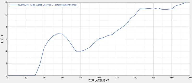
From the above Plot observed that,
Force in the Direction of Displacement. The work done by a constant force is proportional to the force applied times the displacement of the object. During Roof Crush, Maximum force is 12 kN Maximum Displacement is 197 mm at the time t=194ms.
Checking that the FMVSS 216 target load of 47,000 N (= 3 * GVW) with the Simulation result.
Conditions :
a. If GVW is more than 2200 kg,
Resistive Force = 1.5 * GVW
b. If GVW is less than 2200 kg
Resistive Force = 3 * GVW
GVW for the given model = 175.41 kg (GVW is Multiplied with 9.81 to convert kg to N),
Resistive Force = 3 * GVW * (9.81 / 1000)
= 3 * 175.41 * 0.00981
Resistive Force = 5.16 kN (as per FMVSS 216 target load)
- By Comparing FMVSS 216 target load as 5.16 kN and Force obtained from the roof crush simulation is 12 kN. The simulation result is higher than the target load. So we know that the Model is failed due to the Crash event.
Energy Plot :
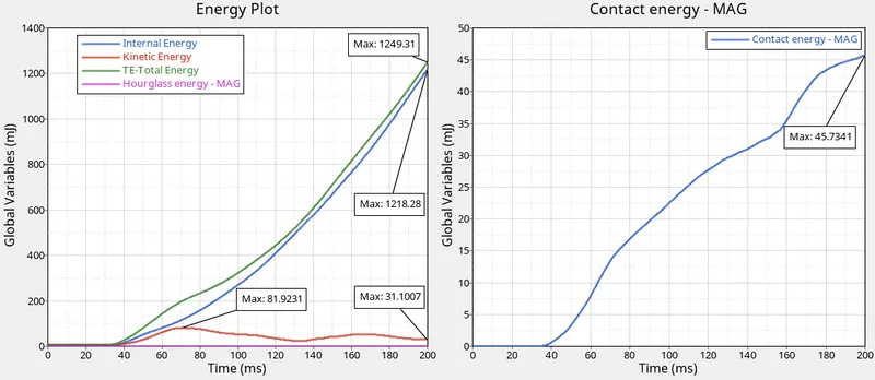
From the above Energy Plot we observed that,
- For the first 40 ms there is no crush between BIW Component and Impactor. After 40 ms roof Crush starts and Internal Energy starts to gain the energy of the system due to changes in its internal state, and Maximum Internal Energy is 1218.28 mJ is generated.
- Kinetic energy (KE) of an object is the energy that it possesses due to its motion. In the Simulation, the Vehicle is in rest condition, so there is no Kinetic energy will be generated. After 40 ms roof Crush starts and Maximum Kinetic energy 81.9231 mJ at time t=70 ms will be created because the vehicle is in motion due to sudden impact on the car by the impactor. At the end of the simulation, Kinetic Energy is 31.1007 mJ at time t=200 ms.
- We Know that Total Energy remains constant(no loss or generation of energy), Kinetic Energy decreases while Internal Energy Increases. But in this less Kinetic Energy and more Internal Energy is generated. So that Total Energy is 1249.31 at t=200ms.
- Contact Energy is a Combination of Penetration and Contact Force (between Master & Slave Nodes). For the first 40ms, there is no crash between BIW Component and Rigid Wall, After 40 ms Side Crash starts and Contact Force is a force applied between Master & Slave nodes and energy required to resist the Penetration of Master & Slave Node So that Contact Energy is increased up to 45.7341mJ.
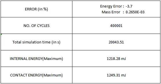
Error Result :
1. After Running the Simulation, Open the Engine OUT File from the saved folder and Check the Energy Error & Mass Error.
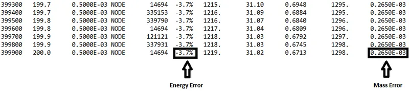
2. Energy Error is -3.7%(better to have within -5%) and Mass Error is 0.000265%.
CONCLUSION :
As per FMVSS No.216 requirement Roof Crush Resistance, vehicle crashworthiness is evaluated by conducting a roof crush test at an impact displacement from 0 mm/s at t = 0 to 200mm/s at t=200. Energy Error, Mass error, Total Simulation run time, Displacement, Vonmises stress, Energy Absorption, Hourglass Energy, Equivalent Plastic strain, Nodal added maas has been evaluated during crash simulations, and results were displayed.