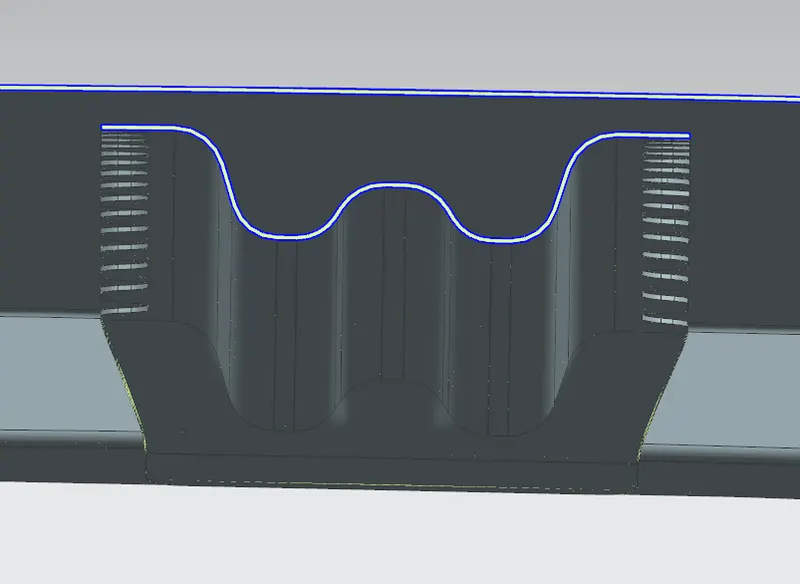
Roof challenge
ROOF DESIGNING
The design and Functional requirements for the roof are,
- Visibility criteria
- Head clearance
- Curvature study
- Heat distortion and snow load criteria.
When we are designing a roof, we should take care of these things. Considering the visibility criteria, the driver should have a good view to the front and back side of the car. There should be a minimum head clearance gap for the passengers. And curvature of the roof should be analysed for the strength study and palcing the reinforcements to improve the strength. Also heat distrotion and snow load criterias has to be checked.
Heat distortion temperature or heat deflection temeperature is a measure of a material resistance to alteration under agiven load at an elevated temperature. The snow load criteria is checked mainly for the cars designed for snow fall regions. In snow region the snow falls will be accumulated on the roof, so the roof should have the strength to be bear the load. These all are checked practically trial and error.
We can design roof in many ways, there are many types of roof styles are available in our market, here we are designing a simple roof considering the design and functional requirements. If we needed can add sun roofs, so we have to adjust the rails respectively. And also if we are providing sun roof, we have to provide an extra reinforcement for the Centre rail. But here we did'nt done here. Also can provide the mounting areas for the interior lights as per our requirements.
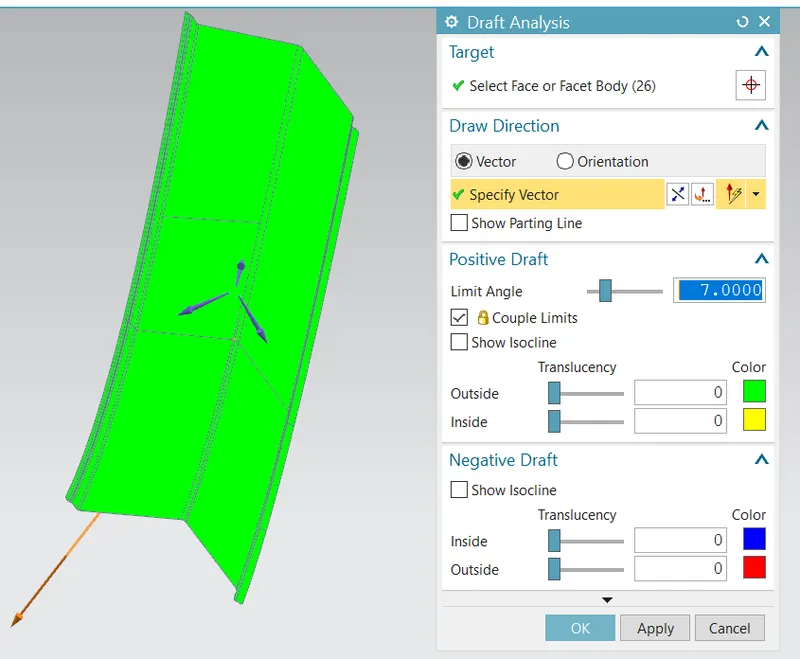
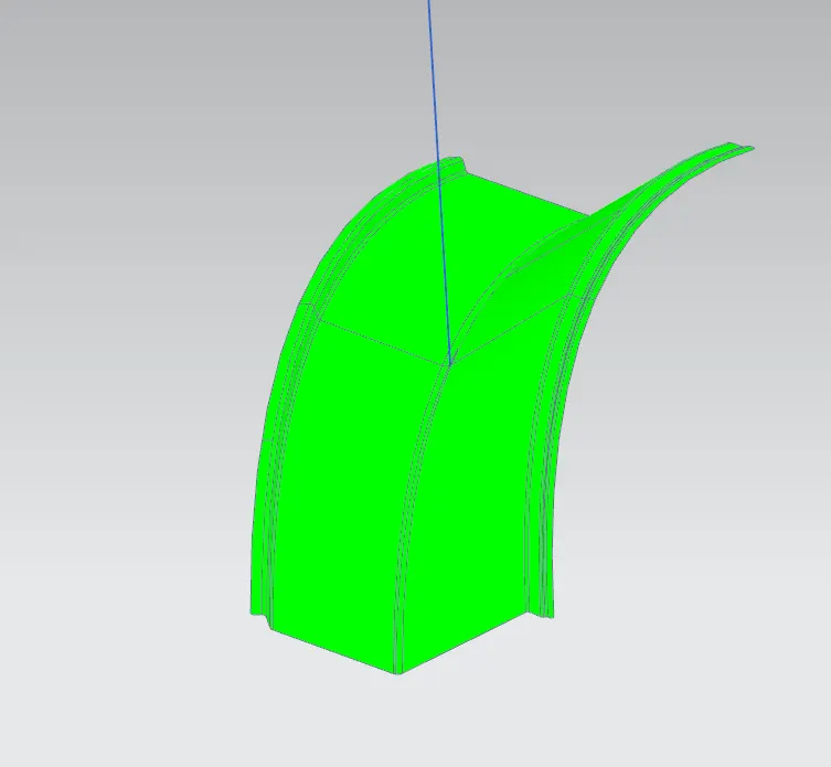
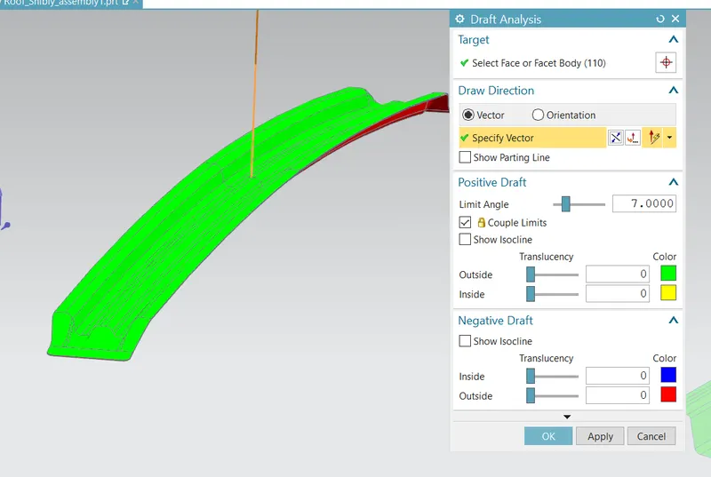
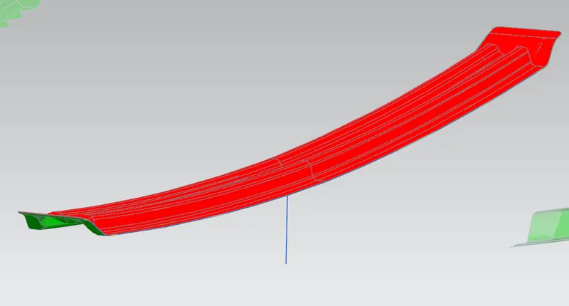
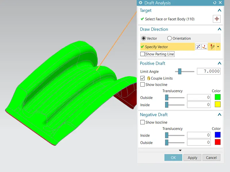
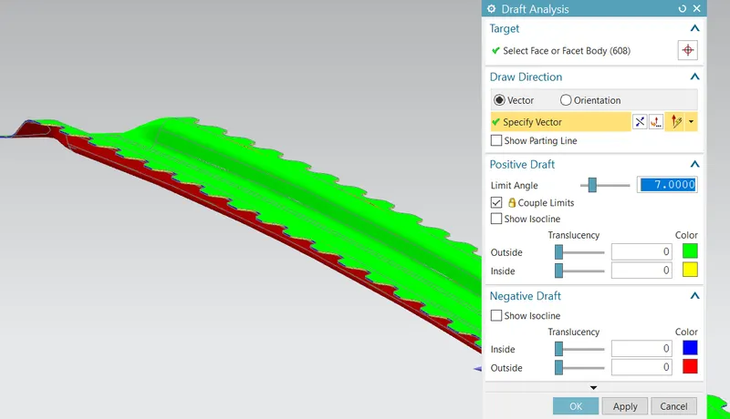
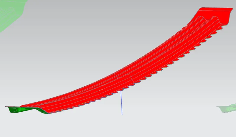
Drafting analysis and its pictures are mentioned for our design.
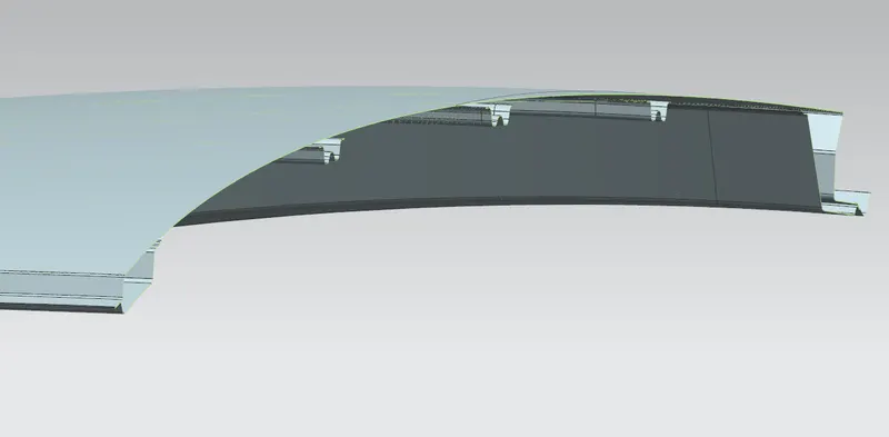
Completed Roof pictures
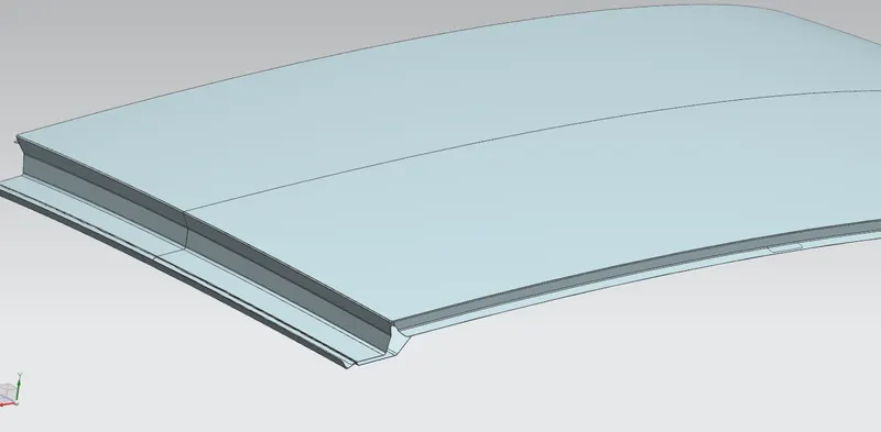
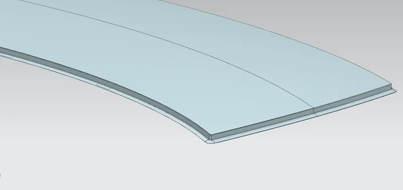
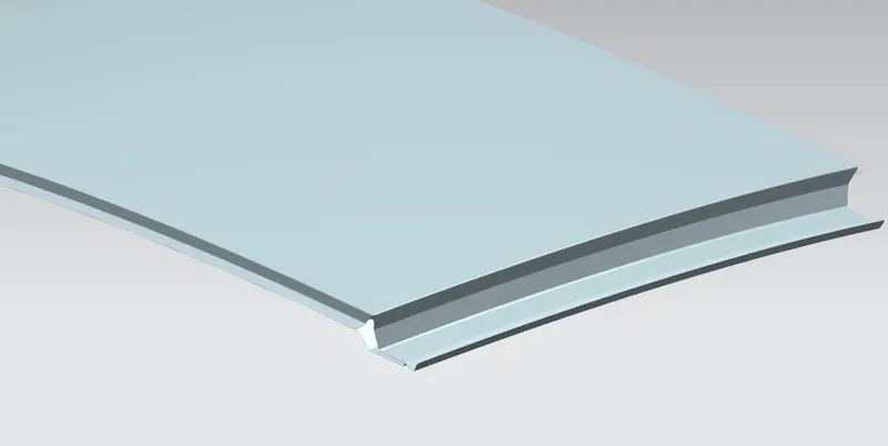

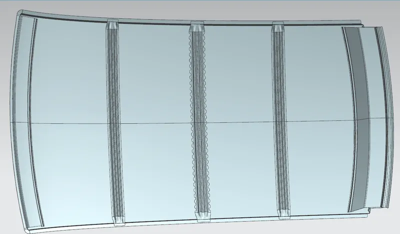
Section view-
Drafting Analysis
Front Roof Rail:
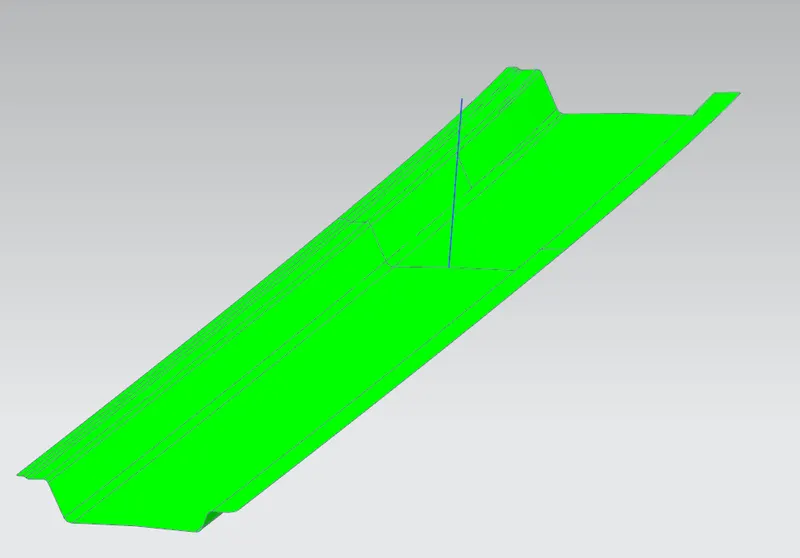
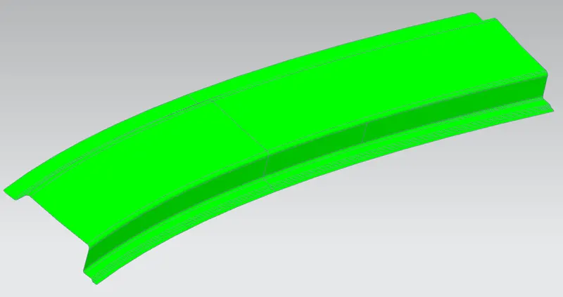
Rear Roof Rail:
Bow Roof Rail 1:
Solid body-
Surface-
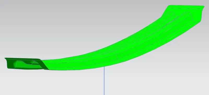
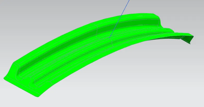
Bow Roof Rail 2
Solid Body-
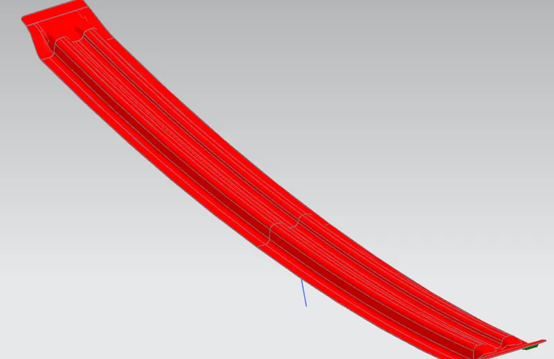
Surface-
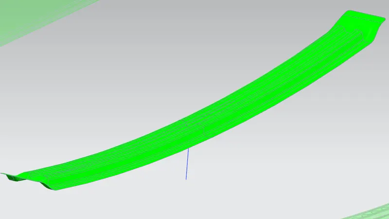
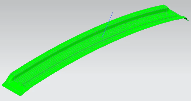
Centre Roof Rail
Surface-
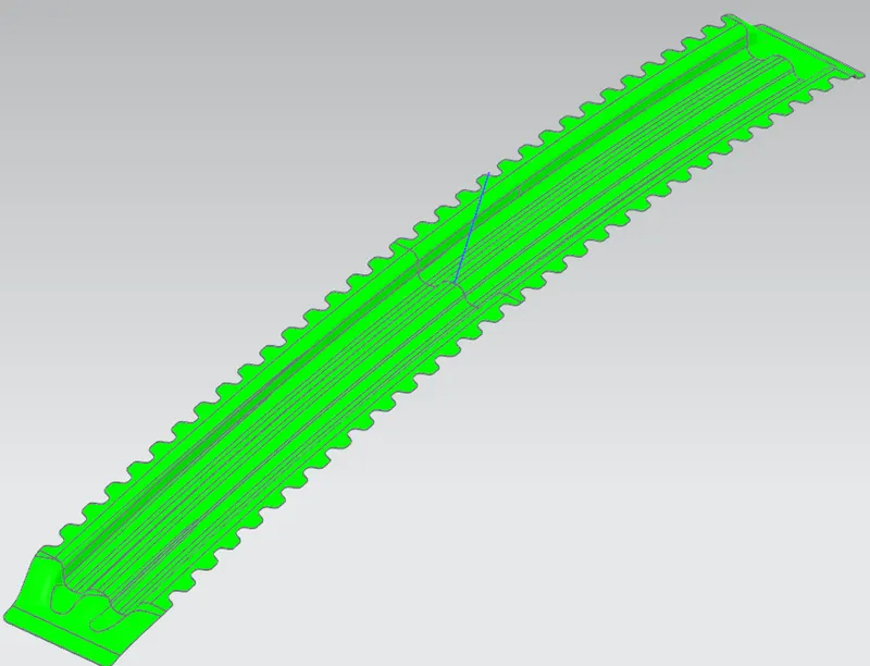
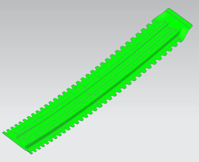
Solid Body-
Heat Distortion Calculation
W=[1.73*10^(-3)*L] + [1.85*10^(-8)*(R^2)/t] + [1.10*10^(-3)*I] - 2.68
Section 1
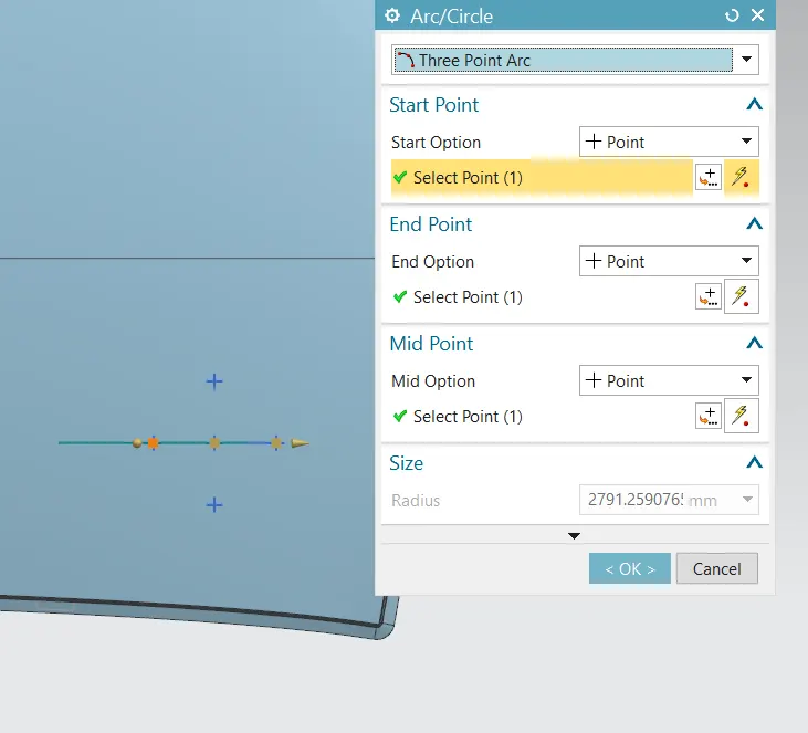
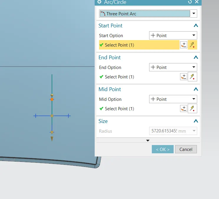
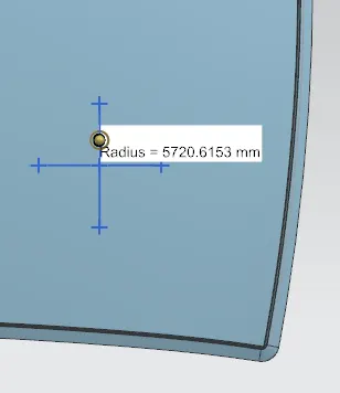
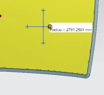
Here we got, Rx=2791 mm
Ry=5720 mm
R=2(Rx*Ry)/(Rx+Ry)
=2(2791*5720)/(2791+5720)
=3751.5 mm
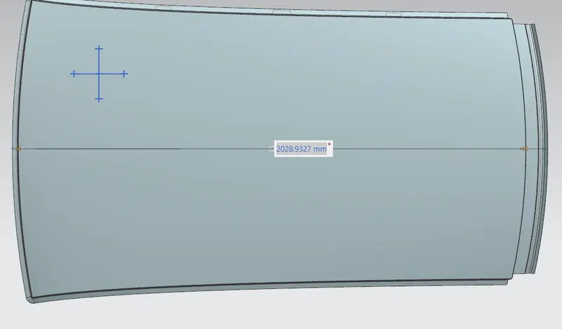
L= 2028.9 mm
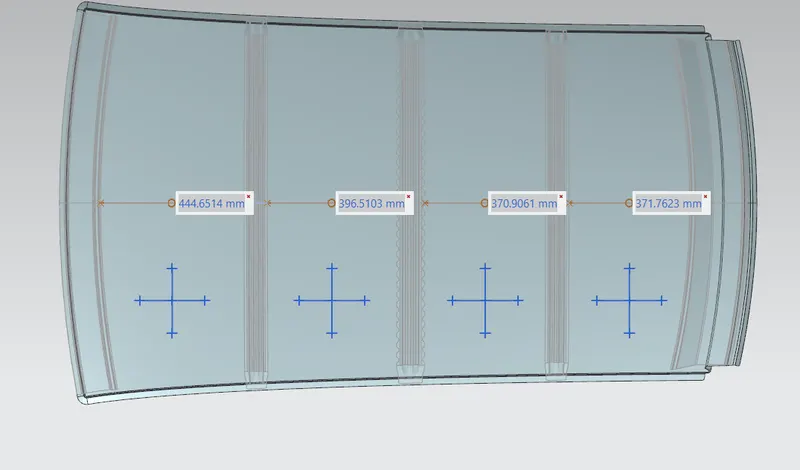
I =444.65 mm
t= 0.75mm
W=[1.73*10^(-3)*L] + [1.85*10^(-8)*(R^2)/t] + [1.10*10^(-3)*I] - 2.68
=[1.73*10^(-3)*2028.9] + [1.85*10^(-8)*14073752.25/0.75] + [1.10*10^(-3)*71.9] - 2.68
=1.668 < 2.7 , So the condition here satisfies
Similarly,
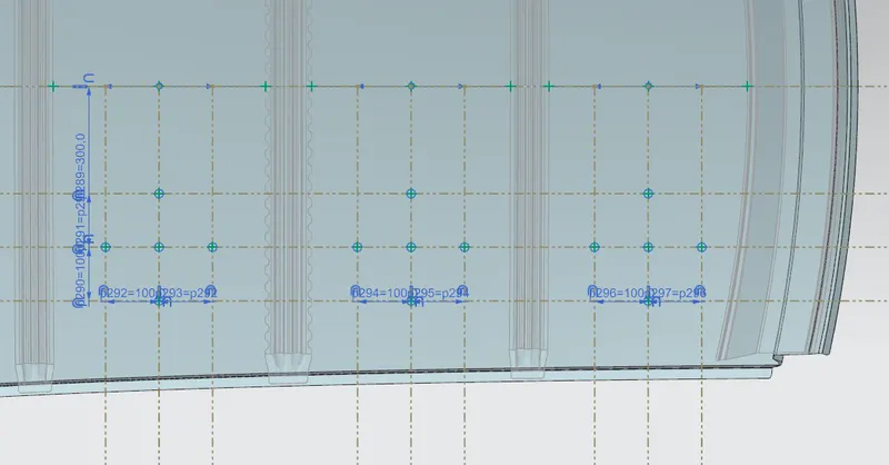
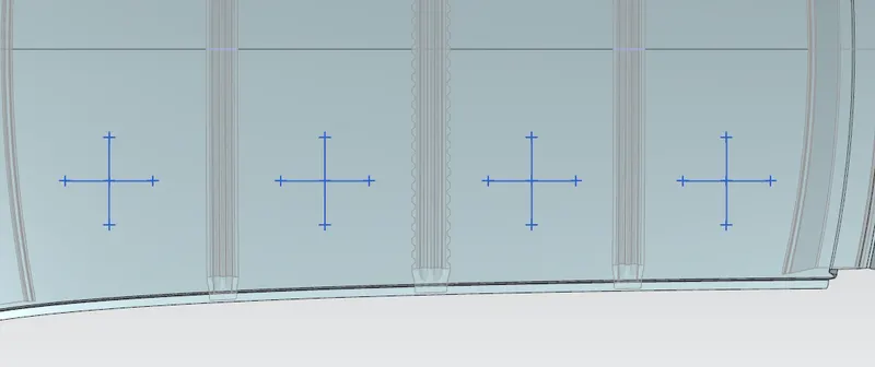
| Section | L | Rx | Ry | t | I | R | W | W_result |
| FR-BR1 | 2029 | 2791 | 5720 | 0.75 | 444.65 | 3751.5028 | 1.66643807 | ok |
| BR1-CTR | 2029 | 6663.2 | 4855.2 | 0.75 | 396.5 | 5617.3025 | 2.04465416 | ok |
| CTR-BR2 | 2029 | 10685.2 | 3956 | 0.75 | 370.9 | 5774.2058 | 2.06058251 | ok |
| BR2-RR | 2029 | 14527.1 | 3288.4 | 0.75 | 371.7 | 5362.8487 | 1.94845694 | ok |
Here we can see the difference in the W value with the change in curvature of the roof. when taking the centre of the roof, there has a big radius of curvature, so the W is about to reach the boundary of the judgement condition.
we have done a section modulus study in previous challange there we understood that if we increases the thickness we can achieve a good strength for the parts. also if we are able to provide a less radius of curvature the area will increase and can achieve good strength.
Snow Load Calculation:
Qr = [Iy*t^2]/[α*s*[(Rx*Ry)/2]^2 *10^(-8)]
Where,
α = My * Lx2 * 10-12, My = Y(Ly-Y)
t = Roof plate thickness [mm]
Ly = Distance between the front and rear roof Rails on the Vehicle along with 0Y[mm]
Length of Roof panel with the center point between Roof rail Front /Rear as the front and rear reference point.
Lx = Distance between the Left and Right end of the roof on the Roof BOW [mm]
The width of the roof panel is exposed on the surface.
Y = Distance front Roof Rail to Roof BOW [mm]
s = Distance for which Roof BOW bears divided load [mm]
s = L1/2 + L2/2
Iy = Geometrical moment of inertia of Roof BOW (Y cross-section)[mm4]
Rx = Lateral direction curvature radius of roof panel Y cross-section on Roof BOW [mm]
Roof panel curvature Radius of the Length Lx in Front view
Ry = Longitudinal Direction curvature radius of the Roof panel X cross-section on Roof BOW [mm]
Section 1:
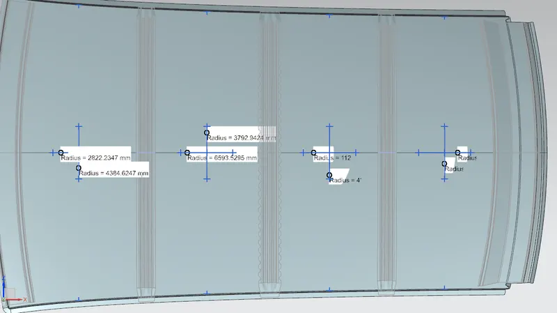
Rx=2822.2 mm
Ry=4384.6 mm
Picture of measurements of Rx and Ry is given below;
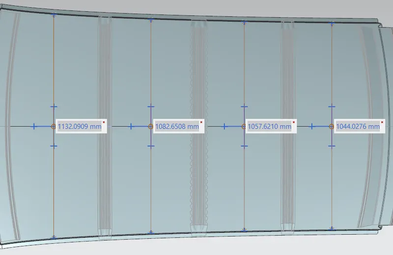
Picture of measurements of Lx in different session is given below;
Picture of measurement of Ly;
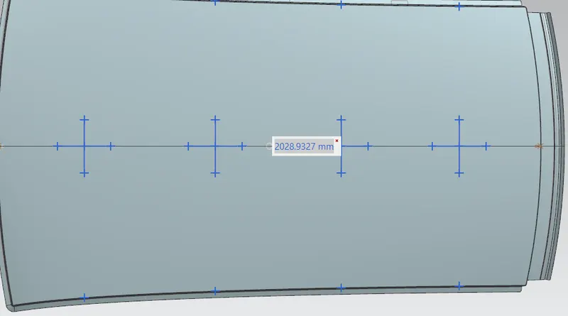
here,
Lx=1132 mm
Ly=2029 mm
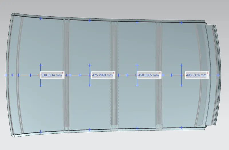
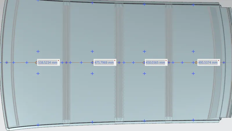
L1=538.5 mm
L2=475.8 mm
Y=538.5 mm
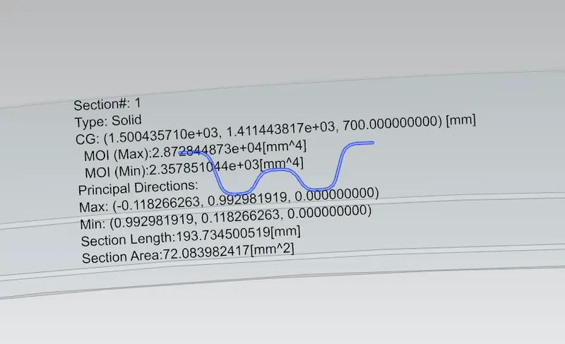
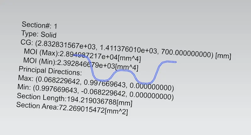
Iy=2591.45 mm^4
s=L1/2 +L2/2
=(538.5/2)+(475.8/2)
=507.15 , s is to be between 250 and 380 here its not satisfying the condition.
My=Y(Ly-Y) = 538.5(2029-538.5) = 802634.25
α=My*Lx^2*10^(-12)
=802634.25*1132^2*10^(-12)
=1.03
Picture of measurements of Y is given below;
Section inertia Iy of Bow rails;
Bow rail01:
cntr rail:
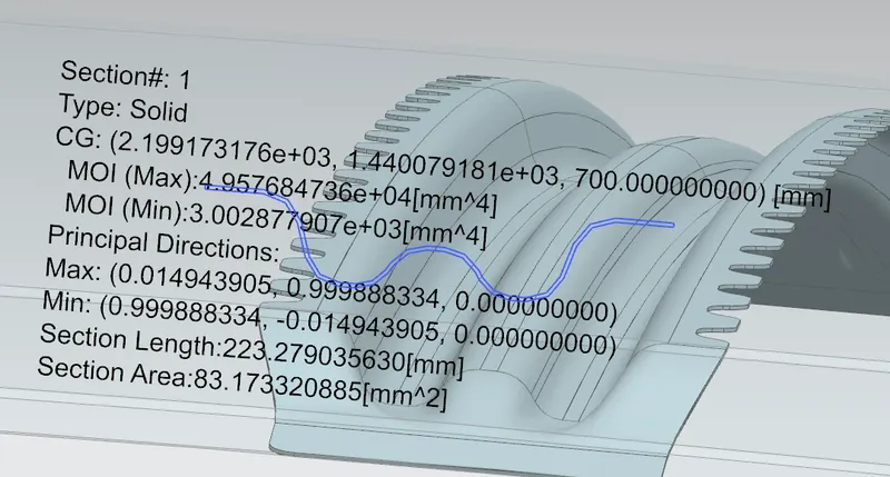
Bow rail02
Measurings of Y
Tabulated Values
| Section | Iy | α | Lx | Ly | Y | s | Rx | Ry | t | Qr | Qr_result | s_result |
| FR-BR1 | 2591.45 | 1.028514791 | 1132 | 2029 | 538.5 | 507.15 | 2822.2 | 4384.6 | 0.75 | 21.52254 | OK | NG |
| BR1-CTR | 3002.9 | 0.86613954 | 1082.6 | 2029 | 475.8 | 462.9 | 6593.5 | 3792.9 | 0.75 | 15.62134 | OK | NG |
| CTR-BR2 | 2614.2 | 0.794762794 | 1057.6 | 2029 | 450 | 472.75 | 11209.5 | 4284.04 | 0.75 | 6.521552 | OK | NG |
| BR2-RR | 0.828187052 | 1044 | 2029 | 495.5 | 16292 | 4022.8 | 0.75 | #DIV/0! | #DIV/0! | NG |
Here all my Qr values are satisfying the condition, If they are not satisfying the conditions we provide embosses on the roof. And also we can try to increase some more thickness of the sheet. If it is a long car we increse the number of bow roofs to provide more strength.
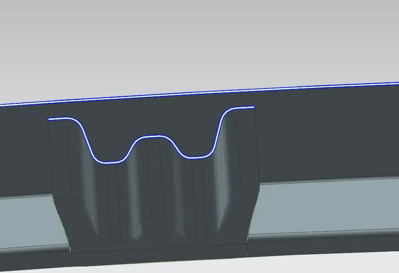
Also we can provide embosses and holes on the rails to provide strength and reduce the weight.
Some sectional views of the completed roof is given below,
rear rail:
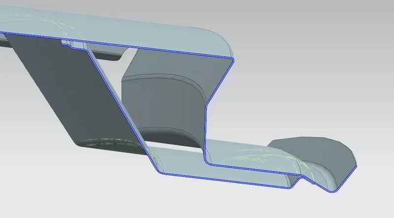
front rail:
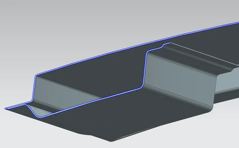
Bow rail:
centre rail: