Roof challenge
AIM:
* To develop the essential flanges and reinforcement with approprite dimensions and checking draft by performance draft analysis ,calculating section inertia ,heat distortion and snow load on the roof.
ROOF:
* An automobile roof of car top is the portion of an automobile that sits above the passangers compartment ,protecting the vehicle occupants from sun,wind,rain and other external elements.
The Automobile roof:
* The outer panel
* front roof rail
* BOW roof
* Centre roof rail
* Rear roof rail
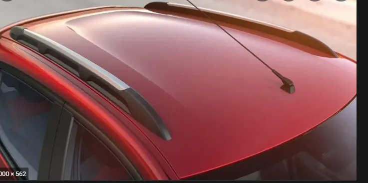
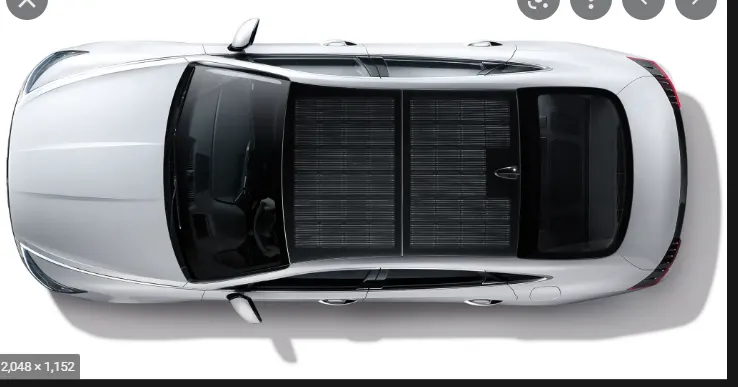
* Sunroofs : A sunroof is a movable panel that opens to uncover a window in an automobile roof, allowing light and/or fresh air to enter the passenger compartment. Sunroofs can be manually operated or motor driven, and are available in many shapes, sizes and styles. While the term sunroof is now used generically to describe any glass panel in the roof, the term "moonroof" was historically used to describe stationary glass panes rigidly mounted in the roof panel over the passenger compartment. A moonroof has a glass panel that is transparent and usually tinted. Previous terms include Sunshine Roof, Sliding Head and Sliding Roof.

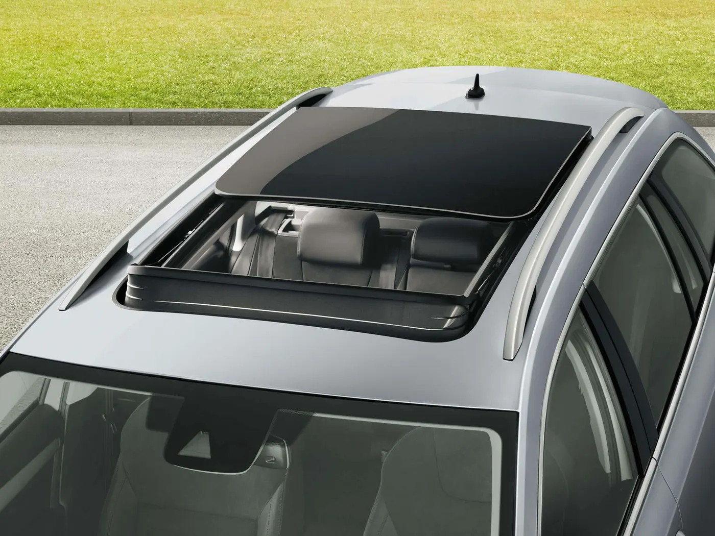
- * Targa Tops - Targa top, or targa for short, is a semi-convertible car body style with a removable roof section and a full width roll bar behind the seats. The rear window is normally fixed, but on some targa models, it is a removable plastic foldable window, making it a convertible-type vehicle. Any piece of normally fixed metal or trim which rises up from one side, over the roof and down the other side is sometimes called a targa band, targa bar, or a wrapover band.
- Targa tops are different from T-tops, which have a solid, non-removable bar running between the top of the windscreen and the rear roll-bar, and generally have two separate roof panels above the seats that fit between the window and central t-bar.
ROOF designed by some criteria:
* Visibility criteria as safety and functionality
* Head clearance for easy and comfort
Roof Skin:
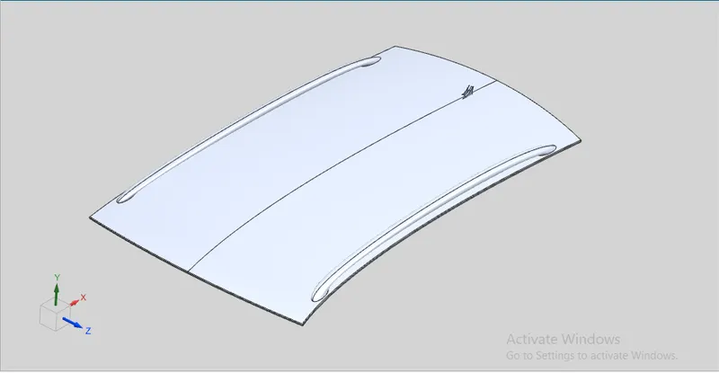
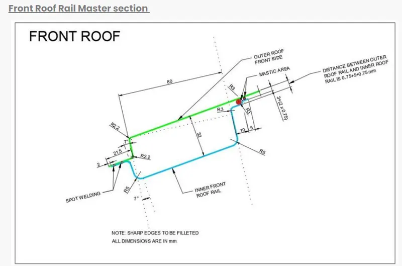
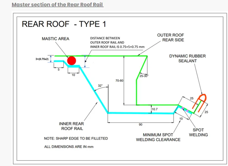
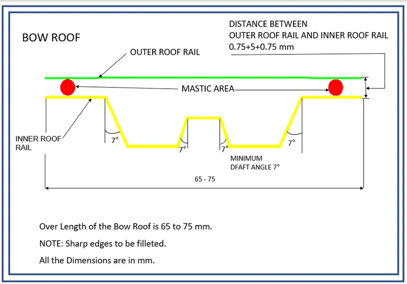
Master section of Bow Roof
FRONT ROOF RAIL:
The front roof rail is created at the front side of the roof to provide strength to the roof. Headroom clearance and the driver visibility are the two important factors to be considered while designing the front roof rail. the front roof rail is connected to the roof outer panel with the help of mastic seal.
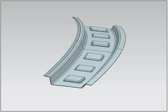
FIG 2. FRONT ROOF RAIL
BOW ROOF:
It is used to give strength to the area between the front roof and the centre roof rail. Also it is created in the area between the centre roof rail and the rear roof rail to provide enough strength. It can be created in any numbers depending upon the roof length but the position of the bow roofs is to be justified by curvature study.
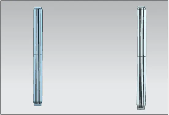
FIG 3. BOW ROOF
CENTRE ROOF RAIL:
It is created at the centre of the roof. It is connected to the roof by mastic seal.
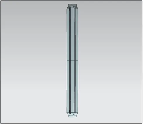
FIG 4. CENTRE ROOF
REAR ROOF RAIL:
It is created at the rear end of the roof. The fitment of the backdoor is to be considered while designing the rear roof rail.
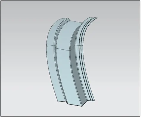
FIG 5. REAR ROOF RAIL
ROOF IMAGES:
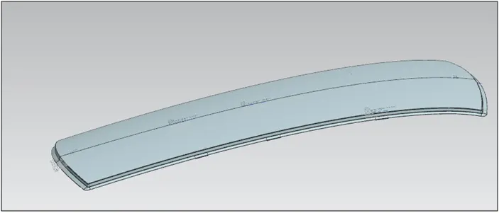
FIG 6. ROOF IMAGE 1

FIG 7. ROOF IMAGE 2
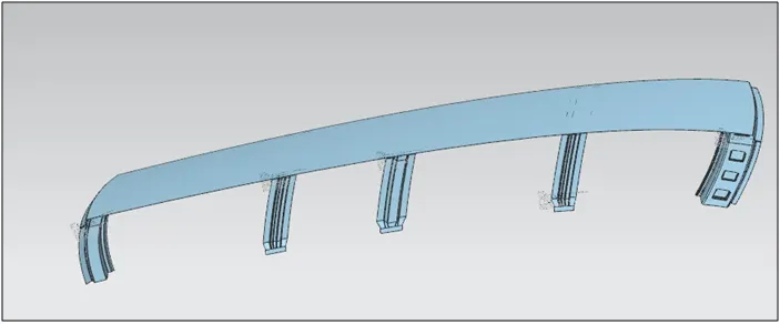
FIG 8. ROOF IMAGE 3
HEAT DISTORTION CRITERIA:
Heat distortion temperature is the temperature at which metal softens and deforms under a specified load. While designing roof, this criteria is taken into consideration. We create bow roofs when the roof is long and flat to increase its strength. The position of the bow roofs is to be justified and this justification is done by curvature study:
Bow - Roof prediction Formula:
W = [1.73 x 10^(-3) x L] + [1.85 x 10^(-8) x (R^2)/t] + [ 1.10x10^(-3) x l] - 2.68
Where,
L = Roof Length in X-Direction[mm](Roof dimension in 0-Y)
R = Roof curvature
R = 2(Rx*Ry)/(Rx+Ry)
Rx = X curvature
Ry = Y curvature
t = Roof plate thickness [mm]
l = Bow Roof Span [mm]
Judgment Condition
OK< 2.7
TO MEASURE L:
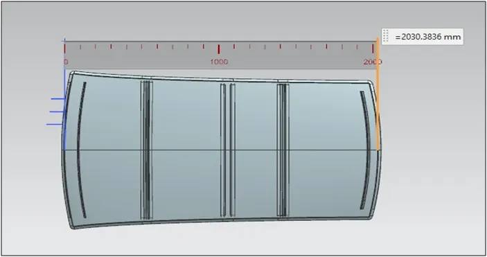
FIG 9: TO MEASURE L
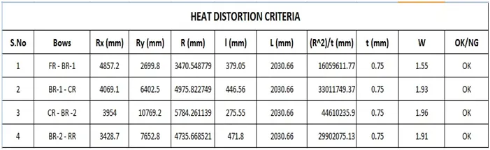
Here we can see that the roof is completely satisfying the conditions of heat distortion.
Snow Load Prediction Formula
Qr = [Iy x t2] / [α x s x [(Rx + Ry)/2]2 x 10-8]
Note: The Qr value given over here is correct. There was a typo error in the formula given in the video.
Where,
α = My x Lx2 x 10-12 , My = Y(Ly-Y)
t = Roof plate thickness [mm]
Ly = Distance between the front and rear roof Rails on the Vehicle along with 0Y[mm]
Length of Roof panel with the center point between Roof rail Front /Rear as the front and rear reference point.
Lx = Distance between the Left and Right end of the roof on the Roof BOW [mm]
The width of the roof panel is exposed on the surface.
Y = Distance front Front Roof Rail to Roof BOW[mm]
s = Distance for which Roof BOW bears divided load [mm]
s = L1/2 + L2/2
Iy = Geometrical moment of inertia of Roof BOW (Y cross-section )[mm4]
Rx = Lateral direction curvature radius of roof panel Y cross-section on Roof BOW [mm]
Roof panel curvature Radius of the Length Lx in Front view
Ry = Longitudinal Direction curvature radius of the Roof panel X cross-section on Roof BOW [mm]
Roof panel X curvature radius of length s in Side view
Judgment condition
Qr ≥ 3.1
250 ≤ s ≤ 380
ROOF
SECTION MODULUS STUDY OF THE SECTION OF THE ROOF RAILS:
The section modulus of the cross-sectional shape is of significant importance in designing of structures. It is a direct measure of the strength of the structure
A structure that has a larger section modulus than another will be stronger and capable of supporting greater loads.
Section modulus (S) = I/y
Where,
I = Moment of inertia in (mm4)
y = Distance between the neutral axis and the extreme end of the object (mm)
FRONT ROOF RAIL:
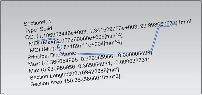
FIG 20. FRONT ROOF RAIL SECTION INERTIA ANALYSIS
I = 10871.9 mm^4
y = 114.28mm / 2 = 57.14mm
S = I/y = 190.27mm^3
BOW ROOF 1
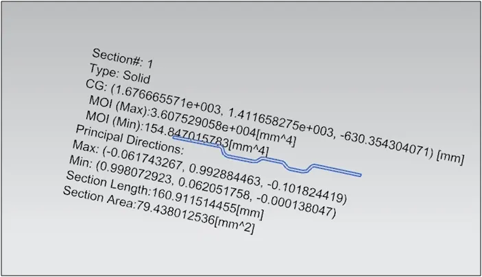
FIG 21. BOW ROOF 1 RAIL SECTION INERTIA ANALYSIS
I = 154.8 mm^4
y = 74.97mm / 2 = 37.49 mm
S = I/y = 4.13mm^3
CENTRE ROOF RAIL:
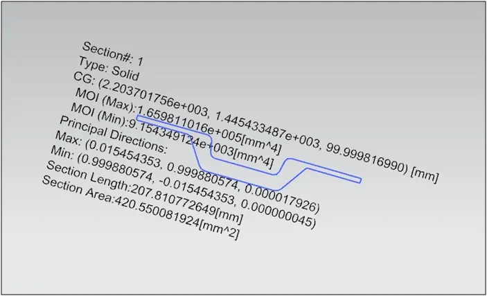
FIG 22. CENTRE ROOF RAIL SECTION INERTIA ANALYSIS
I = 9154.3 mm^4
y = 89.99mm / 2 = 44.99 mm
S = I/y = 203.45mm^3
BOW ROOF 2
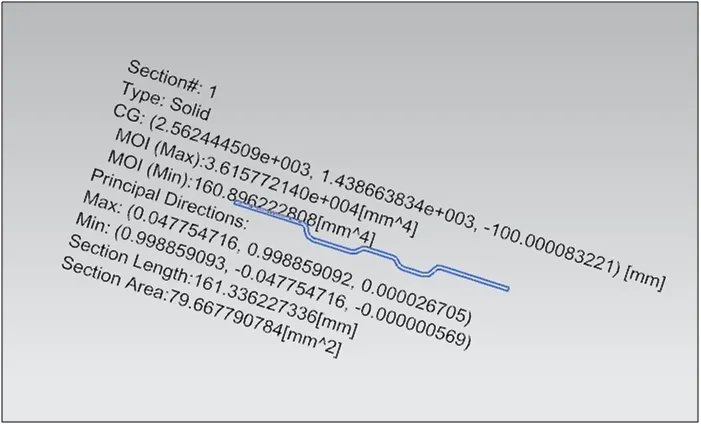
FIG 23. BOW ROOF 2 RAIL SECTION INERTIA ANALYSIS
I = 160.89 mm^4
y = 75.84mm / 2 = 37.92 mm
S = I/y = 4.24mm^3
REAR ROOF RAIL:
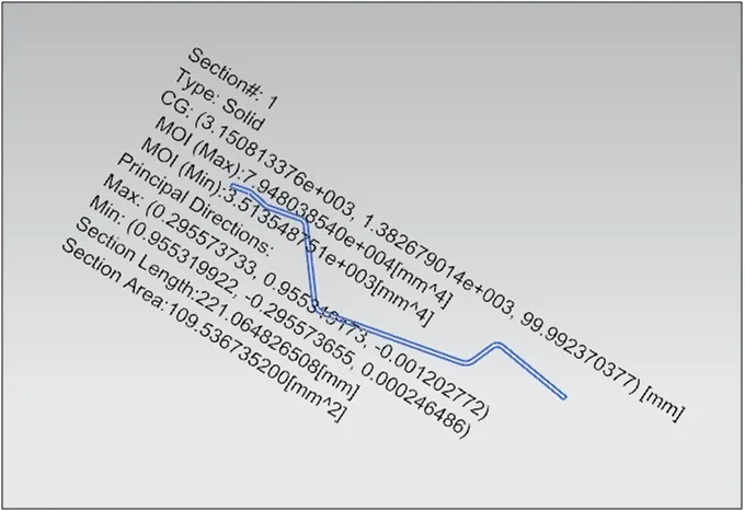
FIG 24. REAR ROOF RAIL SECTION INERTIA ANALYSIS
I = 3513.54 mm^4
y = 91.73 mm / 2 = 45.86 mm
S = I/y =76.61mm^3
DRAFT ANALYSIS:
In NX to check whether the sheet metal part we have designed can be deep drawn, there is an option called draft analysis. This type of analysis is performed based on color ranges identifying zones on the analyzed element where the deviation from the draft direction at any point, corresponds to specified values.
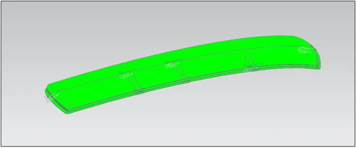
FIG 25. ROOF DRAFT ANALYSIS
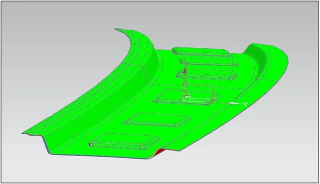
FIG 26. FRONT ROOF DRAFT ANALYSIS
CONCLUSION:
* The Roof was creation in siemens NX student version with all the required parameters and different calculations .