Roof challenge
OBJECTIVE
The Main objective is to design a Roof with Roof rails like Front roof rail, centre roof rail, bow roof rail 1, Bow roof rail 2 and Rear roof rail. Performing a curvature study on the designed roof and calculating the Heat distortion, Snow load criteria, Section modulus and performing Draft analysis to each designed part using Siemens Nx application.
Introduction:
An automobile roof is a BIW component and portion of an automobile that sits above the passenger compartment, protecting the vehicle occupants from sun, wind, rain, and other external elements. Though it just looks like a styling surface that protects from sun, wind, and other elements, various environmental conditions are taken into account for designing the same. The roof should be provided with proper reinforcements for strengthening. Vehicle roofs can be subjected to high heat conditions or load during snowy conditions. To make the roof withstand these conditions, various calculations are done. This ensures the safety of the passengers in the vehicle.
Safety point of view vehicle roof plays a very crucial role especially in rollover kind of accidents, vehicle rollover crashes are the cause for several head,neck and spine injuries for this reason stiffness and strength of any vehicle is crucial, in order to achieve this embosses with reinforcements are provided on the surface of the roof.
DESIGN CONSIDERATIONS
- Visibility criteria
- Crashworthiness of Roof
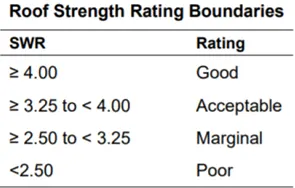
This is a test done on the roof to find the strength-to-weight ratio (SWR) and rate the given car roof. Roof strength evaluations are conducted on a quasi-static test system manufactured by MGA Research Corporation. Once the vehicle is positioned correctly, the roof is crushed to a minimum displacement of 127 mm at a nominal rate of 5 mm/second. The maximum force prior to 127 mm of platen displacement is divided by the measured curb weight to obtain the SWR.
- Head clearance
- Curvature study
- Hear distortion and snow load criteria
Generally, bodies tend to deform when subjected to change in temperature. So, when we design a roof we need to make sure that the roof is able to withstand the extreme climatic changes. Heat distortion criteria tell us if the roof is passing this test or not.
During extreme snow conditions, the roof tends to bend or deform with a heavy application of the snow load. So, when the load due to the snow is removed the roof should go back to its original shape. To check this condition snow load criteria are used to validate the roof.
- Draft analysis.
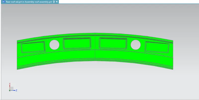
Draft analysis needs to be done for the part after all the design is completed to know whether the part is producible by deep drawing. There should always be a positive draft for the part to be producible. For sheet metal, the draft angle is taken as 7 degrees and sometimes around 5 degrees is also accepted.
ELIGIBILITY CRITERIA
1.For Heat Distortion
Bow-Roof prediction formula:
W= [1.73 x 10^(-3) x L] + [1.85 x 10^(-8) x (R^2)/t] + [1.10 x 10^(-3) x l] – 2.68
Where, L = Roof length in x-direction (0-Y)
Roof Curvature, R = 2 x (Rx.Ry)/[Rx + Ry]
t= Roof plate thickness
l = Bow roof span
Judgment condition: W< 2.7
RX & RY (X & Y Curvature):
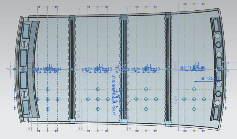
- From 0-Y axis, at -3Y about distance 300mm is drawn parallel on the perpendicular plane. After that 100mm lines are offset to either side of -3Y line. Now center lines are drawn between each adjacent roof rail edges respectively. Intersection points are marked on the sketch. Make all geometry lines are construction lines except points.
- Project the intersection points on sketch to the Roof surface.
- Join the intersection points in roof surface using the arc curve an measure the radius.
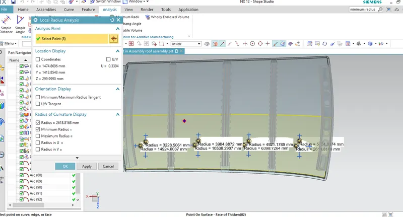

Since heat distortion criteria satisfied all the components no changes would be required.
2.For Snowed Criteria
Snow Load Prediction Formula
Qr = [Iy x t2] / [α x s x [(Rx + Ry)/2]2 x 10-8]
Where,
α = My x Lx2 x 10-12 , My = Y(Ly-Y)
t = Roof plate thickness [mm]
Ly = Distance between the front and rear roof Rails on the Vehicle along with 0Y[mm]
Length of Roof panel with the center point between Roof rail Front /Rear as the front and rear reference point.
Lx = Distance between the Left and Right end of the roof on the Roof BOW [mm]
The width of the roof panel is exposed on the surface.
Y = Distance front Front Roof Rail to Roof BOW[mm]
s = Distance for which Roof BOW bears divided load [mm]
s = L1/2 + L2/2
Iy = Geometrical moment of inertia of Roof BOW (Y cross-section )[mm4]
Rx = Lateral direction curvature radius of roof panel Y cross-section on Roof BOW [mm]
Roof panel curvature Radius of the Length Lx in Front view
Ry = Longitudinal Direction curvature radius of the Roof panel X cross-section on Roof BOW [mm]
Roof panel X curvature radius of length s in Side view
Judgment condition
Qr ≥ 3.1
250 ≤ s ≤ 380
RX & RY (X & Y Curvature):
- At 0-Y axis on perpendicular plane to roof. Draw 100mm lines offset to either side of the of 0Y axis line. Now center lines are drawn between each adjacent roof rail respective. Intersection points are marked on the sketch. Make all the geometry in construction lines except points.
- Project the intersection points in the sketch are projected to roof surface.
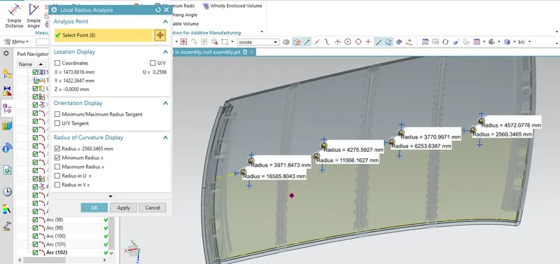
- Join the project points using arc curve and measure the radius value.
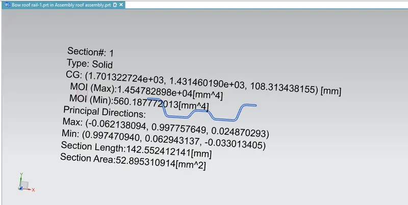
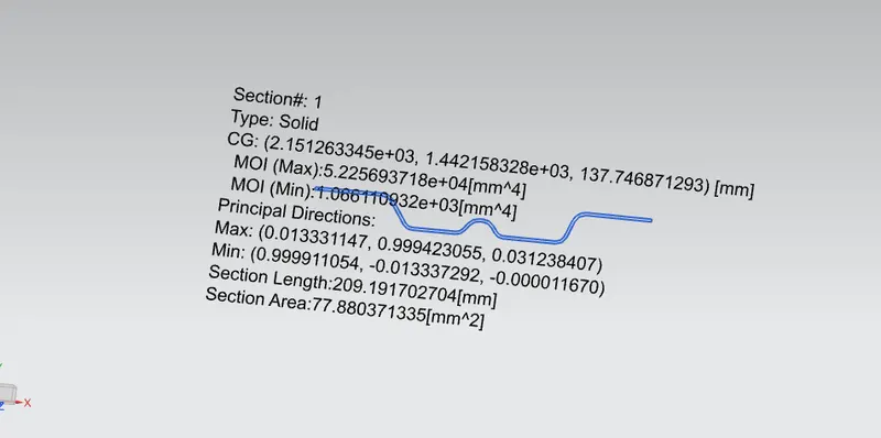
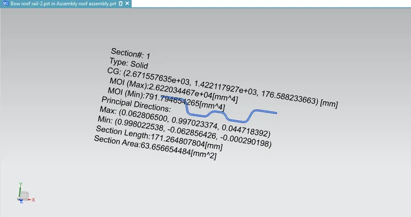
MOI Measurement on Bow roofs and Centre roof rail:

- As you know our Roof design does not get satisfying in the snow load prediction. because in some areas the values were greater than or equal to 3.1
- there are some cases our roof may design may face this kind of problems. To neutralizing this problem we can do some action to get passes in the real-time Snow load test. those are given below.
Redesign the bow to improve the moment of inertia
- make changes in the position of bow's
- make some bead or embossed on the roof to strengthening the roof from its displacement.
- passes the test report to the Styling team to change the radius of curvature of the part.
- Add width or height to the bow roof rails so as to increase the moment of inertia.
- Adding emboses on bow roof rail will inturn increase the strength of the roof
- Adding thickness will drastically increase the strength.
Action
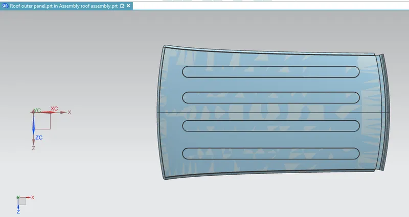
I choose to add some embosses on the roof. so the roof will get passed in the real-time snow load test. the embossed I created drastically improved the strength of the roof.
3.Draft Analysis:
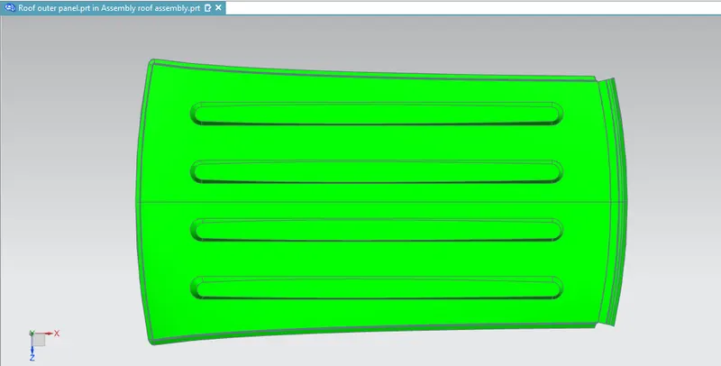
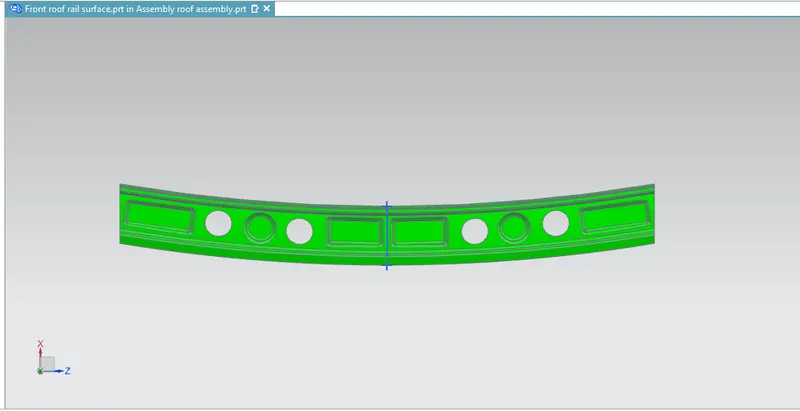
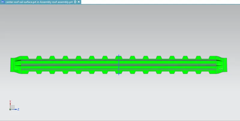
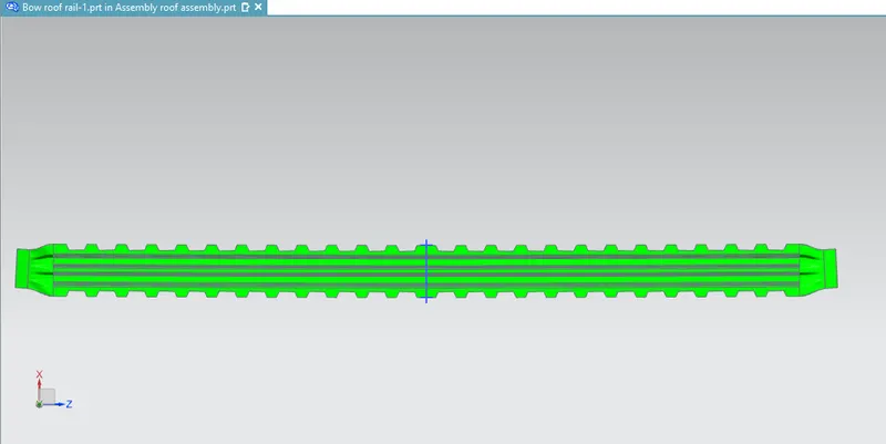
Draft Analysis is done to check whether the part is manufacturable or not. It is not sure shot confirmation that the part is manufacturable, but it is used to check the draft angle on the part. The minimum draft angle is to maintain for sheet metal is 7 mm. The tooling direction for the analysis is perpendicular to the designed part.
Draft Analysis on Roof Outer Panel:
Draft analysis on Front Roof Rail:
Draft analysis on Centre Roof Rail:
Draft analysis on Bow Roof Rail 1:
Draft analysis on Bow Roof Rail 2: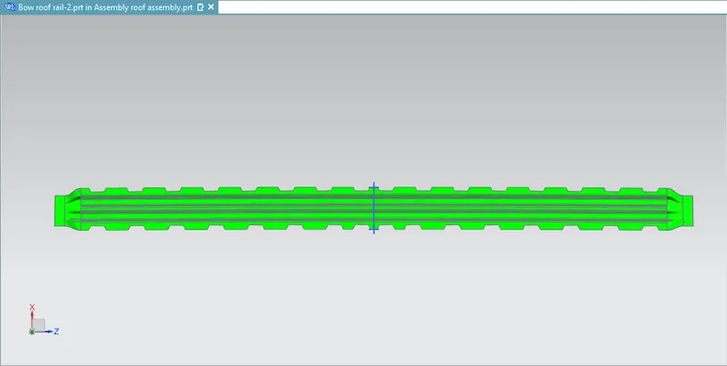
Draft analysis on Rear Roof Rail:
4.Section Modulus:
Section modulus is a geometric property for a given cross-section used in the design of beams. Other geometric properties used in the design include an area for tension, radius of gyration for compression, and moment of inertia for stiffness. The section modulus is defined as
S = I/y
Where,
S = Section modulus
I = Moment of Inertia
Y = Distance from the neutral axis to any given part.
Section Modulus for Roof Outer Panel:
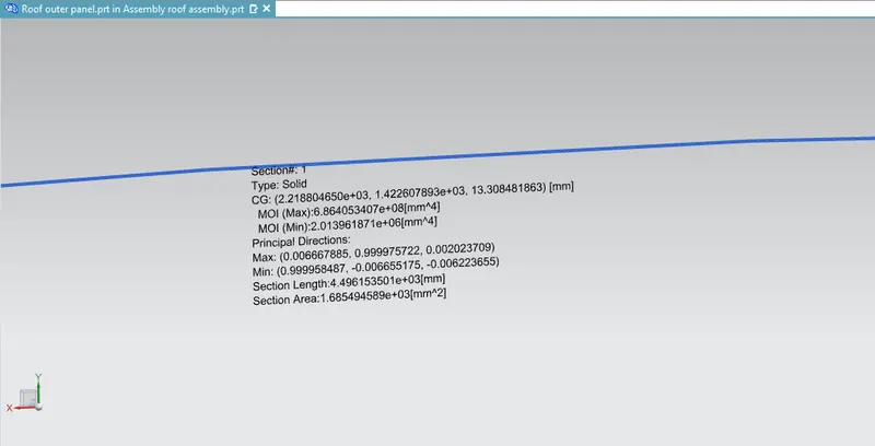
Moment of inertia (Max), Imax = 6.864 x 108 mm4
Moment of inertia (Min), Imin = 2.01396 x 106 mm4
Section modulus = moment of inertia / distance between the neutral axis to extreme end of the object.
S = I/Y
Y = 1060.6637 mm
For maximum MOI,
S = 6.864 x 10⁸/1060.6637
SMAX =647141.973 mm3
For minimum MOI,
S = 2.01396 x 10⁶/1060.6637
SMIN = 1898.7733 mm3
Section Modulus for Front Roof Rail:
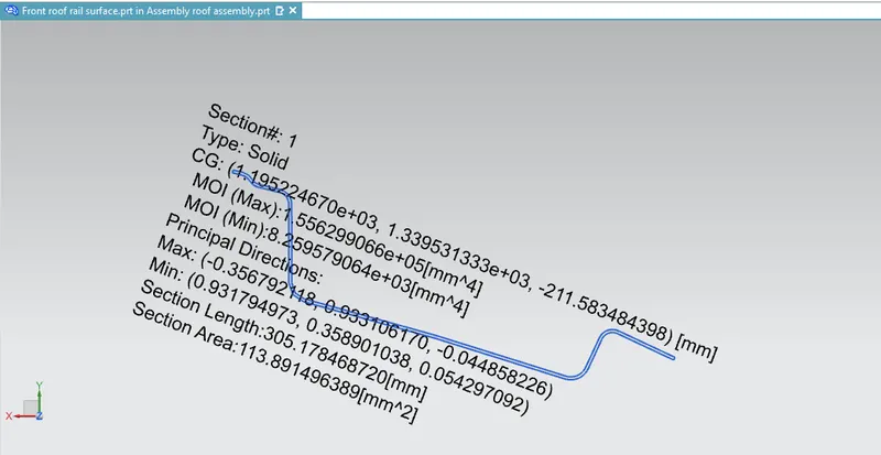
Moment of inertia (Max), Imax = 1.5562 x 105 mm4
Moment of inertia (Min), Imin = 8.2595 x 103 mm4
Section modulus = moment of inertia / distance between the neutral axis to extreme end of the object.
S = I/Y
Y = 57.0713 mm
For maximum MOI,
S = 1.5562 x 10⁵/57.0713
SMAX = 2726.7649 mm3
For minimum MOI,
S = 8.2595 x 10³/57.0713
SMIN = 144.7224 mm3
Section Modulus for Bow Roof Rail 1:
Moment of inertia (Max), Imax = 1.4547 x 104 mm4
Moment of inertia (Min), Imin = 560.1877 mm4
Section modulus = moment of inertia / distance between the neutral axis to extreme end of the object.
S = I/Y
Y = 28.4009 mm
For maximum MOI,
S = 1.4547 x 10⁴/28.4009
SMAX = 512.2020 mm3
For minimum MOI,
S = 560.1877/28.4009
SMIN = 19.7242 mm3
Section Modulus for Bow Roof Rail 2:
Moment of inertia (Max), Imax = 2.622 x 104 mm4
Moment of inertia (Min), Imin = 791.7946 mm4
Section modulus = moment of inertia / distance between the neutral axis to extreme end of the object.
S = I/Y
Y = 35.923 mm
For maximum MOI,
S = 2.622 x 10⁴/35.923
SMAX = 729.8944 mm3
For minimum MOI,
S = 791.7946/35.923
SMIN = 22.0414 mm3
Section Modulus for Rear Roof Rail:
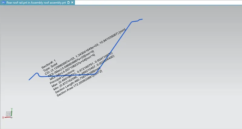
Moment of inertia (Max), Imax = 5.6866 x 105 mm4
Moment of inertia (Min), Imin = 4.0071 x 104 mm4
Section modulus = moment of inertia / distance between the neutral axis to extreme end of the object.
S = I/Y
Y = 87.5891 mm
For maximum MOI,
S = 5.6866 x 10⁵/87.5891
SMAX = 6492.3603mm3
For minimum MOI,
S = 4.0071 x 10⁴/87.5891
SMIN = 457.4884 mm3
Section Modulus for Centre Roof Rail:
Moment of inertia (Max), Imax = 5.2256 x 105 mm4
Moment of inertia (Min), Imin = 1.0661 x 103 mm4
Section modulus = moment of inertia / distance between the neutral axis to extreme end of the object.
S = I/Y
Y = 45.9645 mm
For maximum MOI,
S = 5.2256 x 10⁵/45.9645
SMAX = 11368.7737 mm3
For minimum MOI,
S = 1.0661 x 10³/45.9645
SMIN = 23.1939 mm3
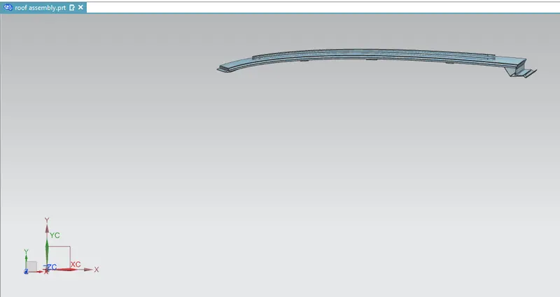
Standard Views:
Top view:
Front view:
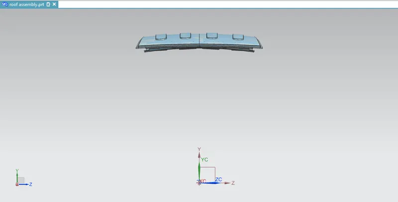
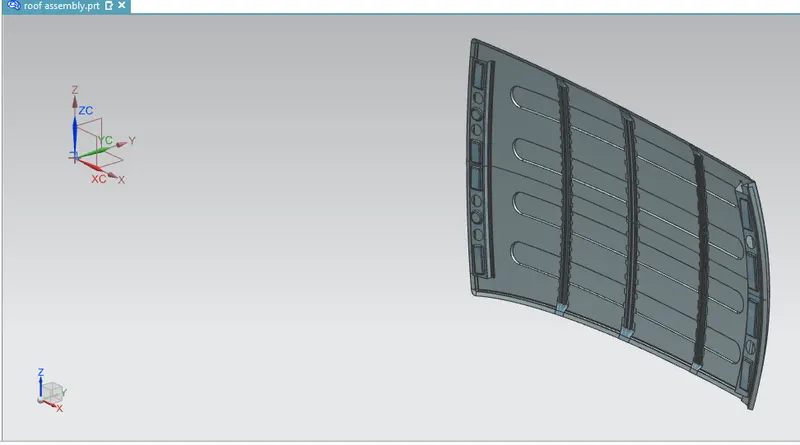
Isometric view:
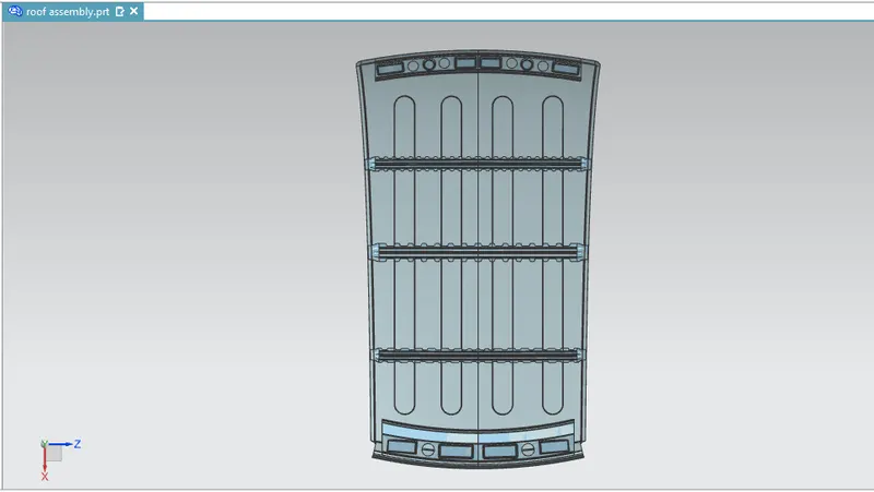
Bottom view:
Side view:
Conclusion:
Finally the Roof design has been completed successfully with the provided styling surface and master sketch parameters. Hence, proved the curvature study, heat distortion, snow load criteria, section modulus and draft analysis.