Roof challenge
OBJECTIVE:
- Designing a car roof panel with the mounting of flanges and reinforcements like ditch area, front roof rail, bow roof rail, center roof rail, and rear roof rail by providing with class A surface.
- Do a curvature study and perform the calculation for the heat distortion and snow load criteria to determine whether the bow roofs are mounting at the correct position.
- Find the section modulus calculation for all roof rails.
- Perform draft analysis.
INTRODUCTION:
- It is an automobile component that lies above the passenger compartment and protects the occupants from the sun, wind, rain, and other external elements such as the roof car top.
- The car ceilings are typically coated with headliners that provide insulation against heat and noise, and also head wires and hardware for electrical components, antennas, and other accessories.
- The roof is generally an integrated part of the body in white and the roof is used to carry the luggage on the roof panel during travel.
DESIGN CONSIDERATION:
- CURVATURE STUDY
- DRAFT ANALYSIS
- SAFETY
- ROOF CRASH ANALYSIS
- HEAT DISTORTION CRITERIA
- SNOW LOAD CRITERIA
- VISIBILITY CRITERIA.
CURVATURE STUDY:
- The roof panel possesses a curved flattened surface.
- The roof curvature should possess strength while applying the load.
- It compromises to keep the bow roof rails at the flattened roof surface.
- The more curvature position of the roof to withstand the more loads and resist bend.
ROOF PANEL CONSISTS OF
- FRONT ROOF RAIL
- REAR ROOF RAIL
- BOW ROOF RAIL
- CENTRE ROOF RAIL
ROOF PANEL:
FRONT ROOF RAIL:
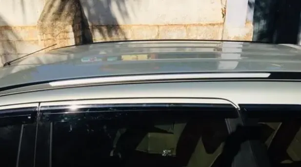
- The front roof rail is a cut part it will be mounting of A-Pillar.
- It has mounting by spot welding. So it doesn’t maintain the clearance between the outer roof panel and front roof rail.
- The spot welded areas to be enclosed by ditch area.
- It acts as a link between windshield glass and the outer roof panel.
DITCH AREA:
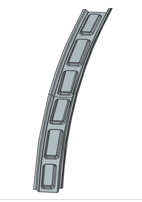
- Ditch area is an extended portion of the main roof connected by other BIW panels.
- The rails support of the roof are attached to the ditch area using spot weld.
REAR ROOF RAIL:
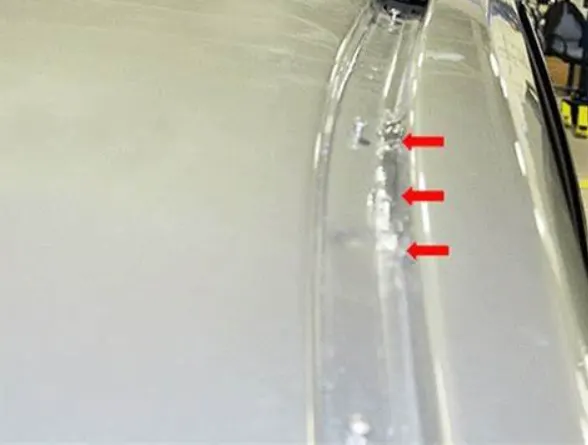
- The rear roof rail is a connected rail with the outer roof and mounting at C-Pillar.
- It also provides the required strength at the rear position of the roof.
- Rear roof lower rail is overlapped by and welded to the inner side panel and the outer side panel is overlapped by and welded to a rear roof upper rail and roof panel, wherein the rear roof lower rail is bent at a tip end thereof and welded to connect the inner side panel and outer side panel respectively.
BOW ROOF RAIL:
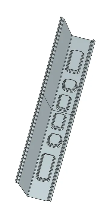
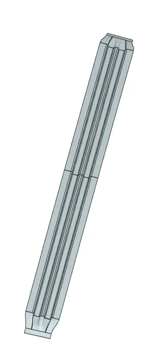
- Bow roof rails are provided for the support of the roof surface.
- The bow roofs are provided with mastic sealant as they are assembled with the surface as welding is not possible.
- The bow roof rail 1 and 2 are provided for better protection of the roof from the crash.
CENTRE ROOF RAIL:
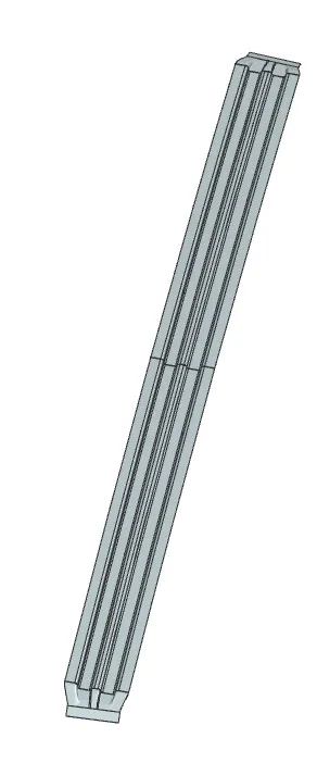
- Centre roof rail mounting at the center of roof panel close to B-Pillar region.
- The center roof rail has two layers (reinforcement) to protect it from roll roll-overrash.
SAFETY:
- A vehicle roof plays a very crucial role, especially in roll-overs kind of accidents in which vehicle tips over onto its side of the roof.
- rollover crashes are causes of many fatalities and several head, neck, and spine trauma around the world.
- Therefore passenger safety is also a very important parameter in front of OEM.
- It is not only the marketing strategy. For this reason, strength is a very important criterion for designing the roof.
ACCIDENTS FROM ROLLOVER CRASHES:

ROOF CRASH ANALYSIS:
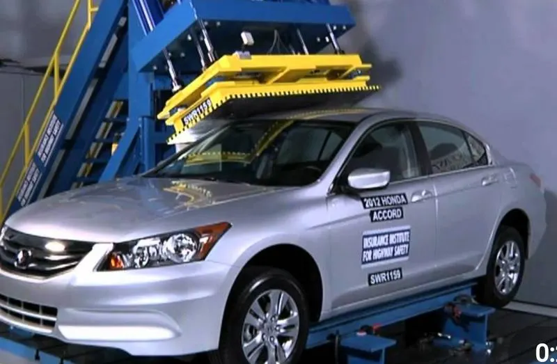
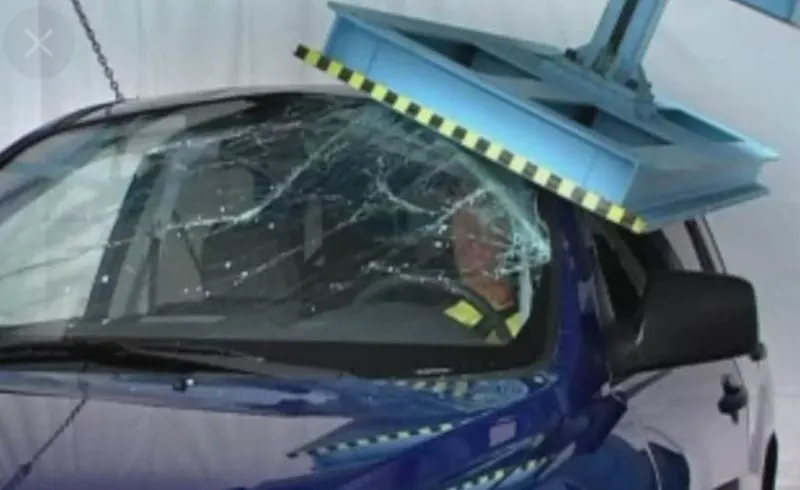
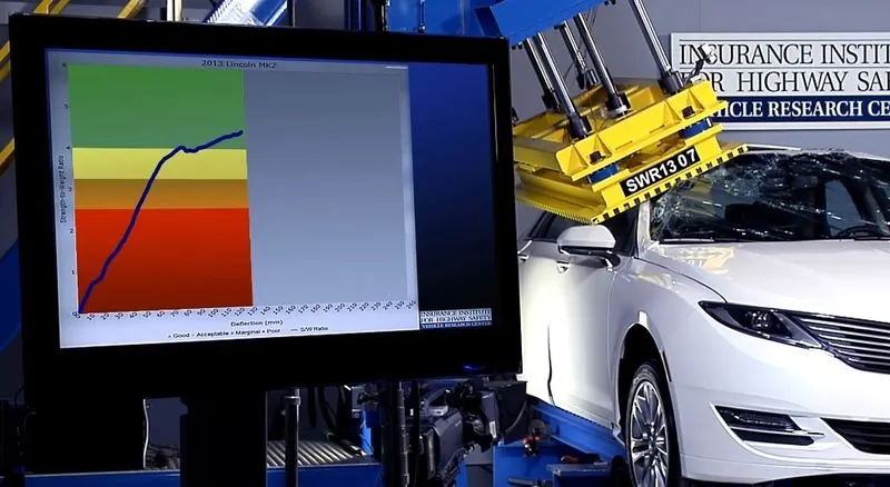
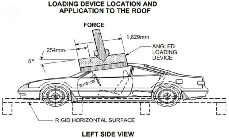
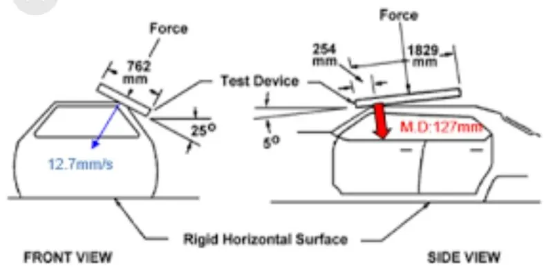
- The National Highway Traffic Safety Administration (NHTSA) mandates the use of certain test procedures to determine automobile roof crush resistance.
- In the test the force-deflection behavior of roof structure is measured by quasi statically pressing the precisely positioned rigid plate against the automobile.
- As part of the design process, the test is often simulated analytically.
- The product can be used to simulate a roof crush resistance test effectively.
VISIBILITY CRITERIA:
- Front and rear ditch area parts are provided with an optimum angle for ensuring the front and rear visibility criteria and production criteria.
HEAD IMPACT ZONE CRITERIA:
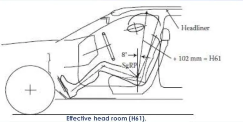
- Minimum of 5 mm of the gap between the inner panel and trim panel is maintained to have a proper head impact zone.
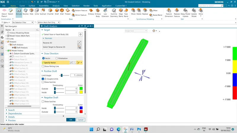
DRAFT ANALYSIS:
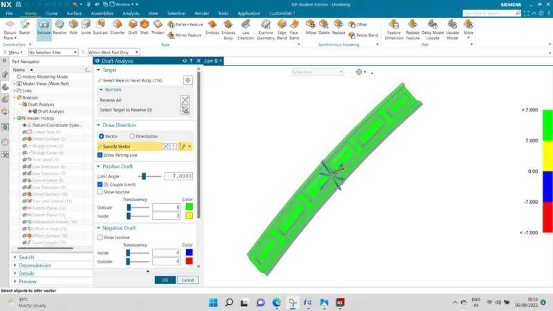
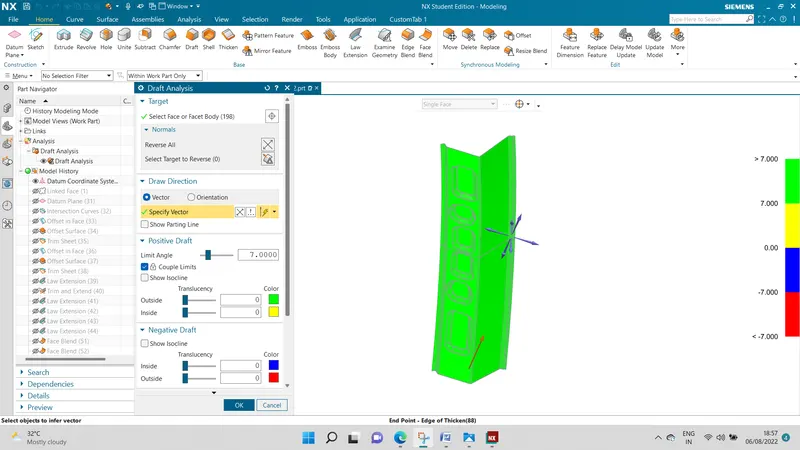
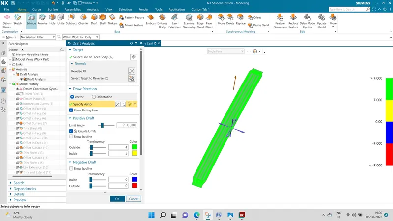
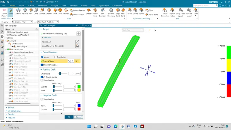
- Draft analysis is done to see whether the metal is drawn with a particular design without any tear in the metal of disfiguration.
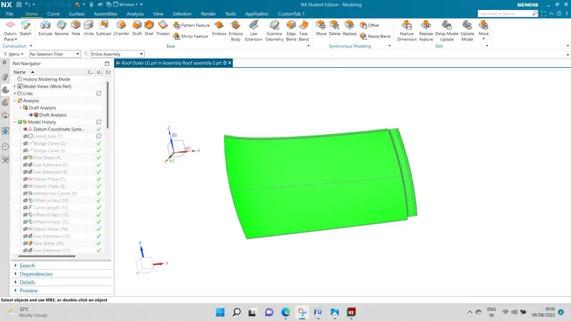
- The performing of draft analysis to reveal the part occupied by a variety of colors ( Green, Yellow, Blue, Red).
- Green is good to go because the greenish part of the product should be fully able for manufacturing.
- It is done with 7 degrees positive of allowance.
FRONT ROOF RAIL:
REAR ROOF RAIL:
CENTER ROOF RAIL:
BOW ROOF RAIL1
BOW ROOF RAIL 2:
ROOF OUTER PANEL:
MANUFACTURING PROCESS:
- The manufacturing process of automobile roof components comprises the following steps respectively consisting of an outer plate processing process a strip-shaped assembly and annular assembly processing process and an automobile roof side beam processing process, finally, an automobile roof combining process comprises the following steps.
- A Plurality of M6 Screw nuts is arranged on one side of the annular assembly through spot welding and two M6 screw nuts are arranged at two ends of a strip-shaped assembly through spot welding.
OUTSIDE PLATE PROCESS:
- Open straight snips plate first select applicable cold coiling specification, cold coiling is opened flat.
- Then according to production material specification open cold coiling after flat and be cut into the iron plate of the corresponding size.
- Finally the iron plate after shear cleaned to iron fillings
- the First step is oil pressing and punches press.
- The iron plate is extended secondly to its trimming and punching finally after punching completes, it is carried out to the operation of side folding completed making of the outside plate.
- Bar-shaped assembly and ring-shaped component process.
- The first step, blanking, stamps out iron plate the outline blank of many roof cant rails.
- A ring-shaped component and bar-shaped assembly second step.
- It carries out annular punching to ring-shaped components.
- Bar-shaped assembly and roof cant rail are carried out to bar-shaped punching.
- Finally car roof integral body is carried out to sand the thorn and ending.
MANUFACTURING PROCESS OF ROOF BY COLD OVEN AND HOT OVEN HOT PLATE METHOD:
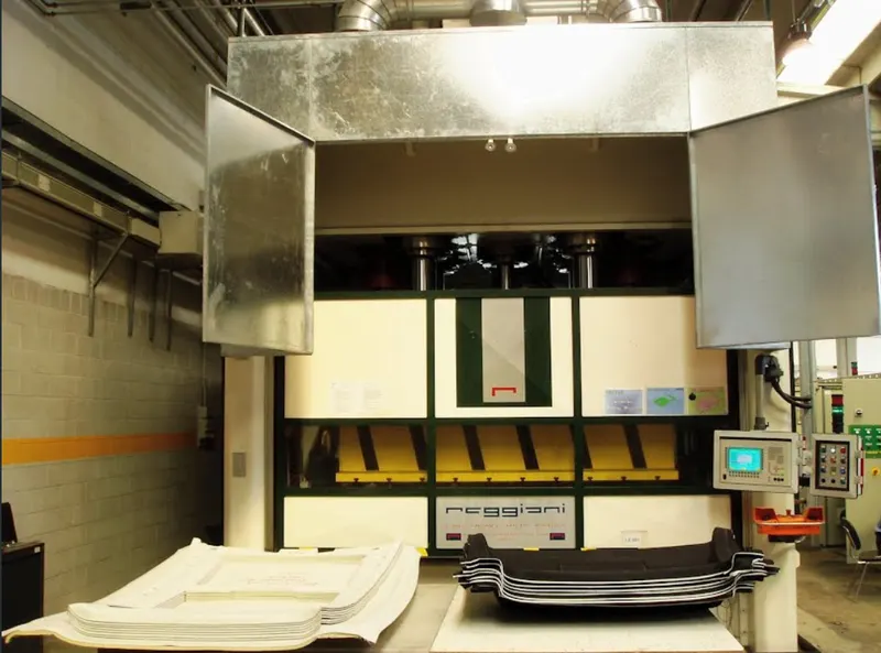
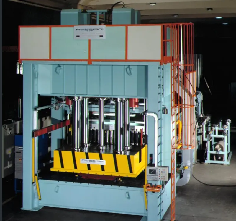
MANUFACTURING PROCESS OF ROOF UNDER PRESSING:
HEAT DISTORTION FORMULA:
- It is the temperature at which material starts softening when exposed to a fixed load at elevated temperature. Above this temperature, material can’t be used.
- To know whether the material is in a safer zone according to the position of bow roofs.
- The test is performed by considering the given formula.
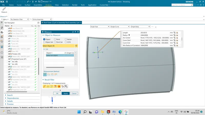
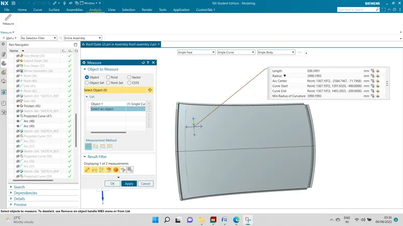
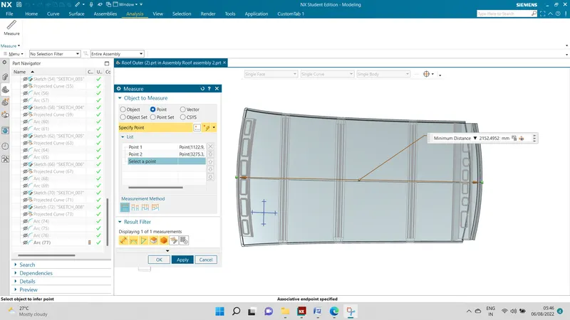
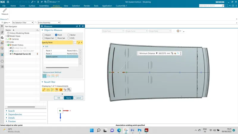
W = [1.73 x 10^(-3) x L] + [1.85 x 10^(-8) x (R^2)/t] + [ 1.10x10^(-3) x l] - 2.68
Where,
L = Roof Length in X-Direction[mm](Roof dimension in 0-Y)
R = Roof curvature
R = 2(Rx*Ry)/(Rx+Ry)
Rx = X curvature
Ry = Y curvature
t = Roof plate thickness [mm]
l = Bow Roof Span [mm]
Judgment Condition
OK< 2.7
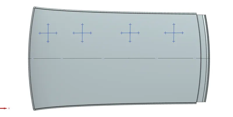
TO MEASURE RX:
TO MEASURE RY:
TO MEASURE L:
To measure l:
TABULAR COLUMN OF HEAT DISTORTION CALCULATION:
|
BOW |
RX |
RY |
R |
t |
l |
L |
W |
W<2.7 |
OK/NG |
|
FRR&1st |
2484.89 |
3990 |
3062.59 |
0.75 |
319 |
2151 |
3.639 |
<2.7 |
NG |
|
1st&CRR |
8455 |
2932 |
4354 |
0.75 |
824.67 |
2151 |
1.953 |
<2.7 |
OK |
|
CRR&2nd |
9957 |
4101 |
5809 |
0.75 |
548 |
2151 |
2.4763 |
<2.7 |
OK |
|
3rd&RRR |
12447 |
2650 |
4369 |
0.75 |
319 |
2151 |
1.8629 |
<2.7 |
OK |
The heat distortion evaluation between the front roof rail and bow roof 1 is not satisfying the above condition.
The remaining are satisfying those conditions.
SNOW LOAD CRITERIA:
Qr = [Iy x t2] / [α x s x [(Rx + Ry)/2]2 x 10-8]
Note: The Qr value given over here is correct. There was a typo error in the formula given in the video.
Where,
α = My x Lx2 x 10-12 , My = Y(Ly-Y)
t = Roof plate thickness [mm]
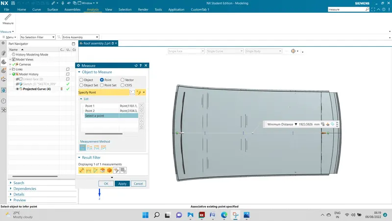
Ly = Distance between the front and rear roof Rails on the Vehicle along with 0Y[mm]
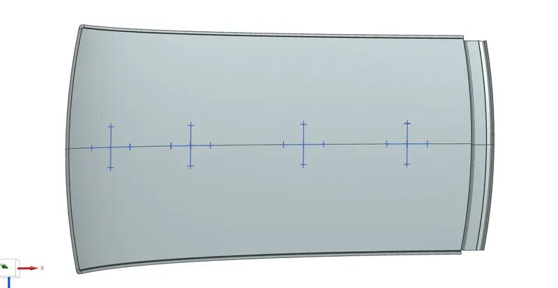
Length of Roof panel with the center point between Roof rail Front /Rear as the front and rear reference point.
Lx = Distance between the Left and Right end of the roof on the Roof BOW [mm]
The width of the roof panel is exposed on the surface.
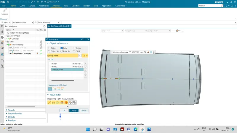
Y = Distance front Front Roof Rail to Roof BOW[mm]
s = Distance for which Roof BOW bears divided load [mm]
s = L1/2 + L2/2
Iy = Geometrical moment of inertia of Roof BOW (Y cross-section )[mm4]
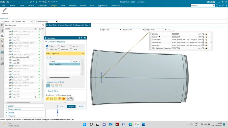
Rx = Lateral direction curvature radius of roof panel Y cross-section on Roof BOW [mm]
Roof panel curvature Radius of the Length Lx in Front view
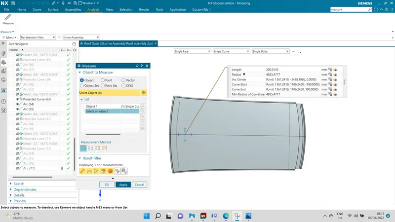
Ry = Longitudinal Direction curvature radius of the Roof panel X cross-section on Roof BOW [mm]
Roof panel X curvature radius of length s in Side view
Judgment condition
Qr ≥ 3.1
250 ≤ s ≤ 380
TO MEASURE RX:
TO MEASURE RY:
TO MEASURE BY:
TO MEASURE LX:
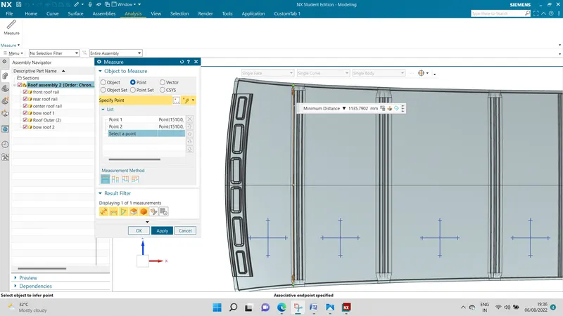
TO MEASURE Y :
TABULAR COLUMN OF SNOW LOAD CALCULATION:
|
S.NO |
BOWS |
Rx (mm) |
Ry (mm) |
Lx (mm) |
Ly (mm) |
Y (mm) |
|
S (mm) |
MY
|
α |
t (mm) |
Iy |
Qr |
OK/NG |
|
1 |
FRR-1stBR |
2208 |
4835 |
1135 |
1923 |
360 |
375 |
562680 |
0.72 |
0.75 |
7216 |
6.53 |
OK |
|
|
2 |
1stBR-CRR |
5077 |
5253 |
1090 |
1923 |
848 |
561 |
911600 |
1.08 |
0.75 |
899 |
3.09 |
NG |
|
|
3 |
CRR-2ndBR |
45630 |
11434 |
1060 |
1923 |
1479 |
539.5 |
656676 |
0.73 |
0.75 |
905 |
3.95 |
OK |
|
|
|
|
It is observed that the roof has satisfied the above two conditions only in the area between the front roof rails and 1st bow roof, the area between the center roof rail, and the 2nd bow roof.
In another area,s it doesn't satisfy the given condition. so to strengthen the roof by creating the emboss.
SECTION MODULUS FOR SECTION OF THE EACH ROOF RAIL:
- The section modulus of the cross-sectional shape is of significance in designing the structures. It is a direct measure of the strength of the structure.
- A structure that has a larger section modulus than another will be stronger and capable of supporting greater loads.
Section modulus (S)= I/Y
I= Moment of inertia(mm^4)
y=Distance between the neutral axis and the extreme end of the object(mm^4)
FRONT ROOF RAIL:
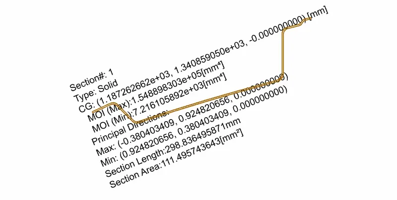
I=721.19(mm^4)
Y=124.5/2
=62.5 mm
S=I/Y
=115.45 mm^3
BOW ROOF 1
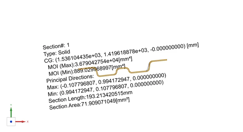
I= 889.02 mm^4
Y= 80/2= 40 mm
S=I/Y=889/40
S=22.225 mm^3
CENTER ROOF RAIL:
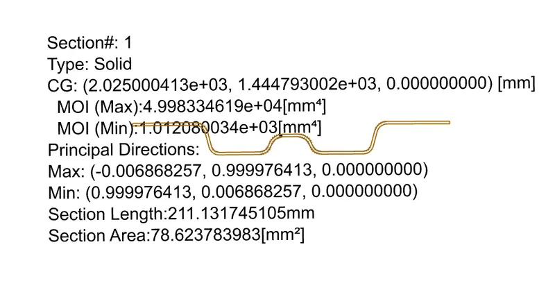
I=1012 mm^3
Y= 89.9/2=44.9
S=I/Y
S=22.5 mm^3
BOW ROOF 2
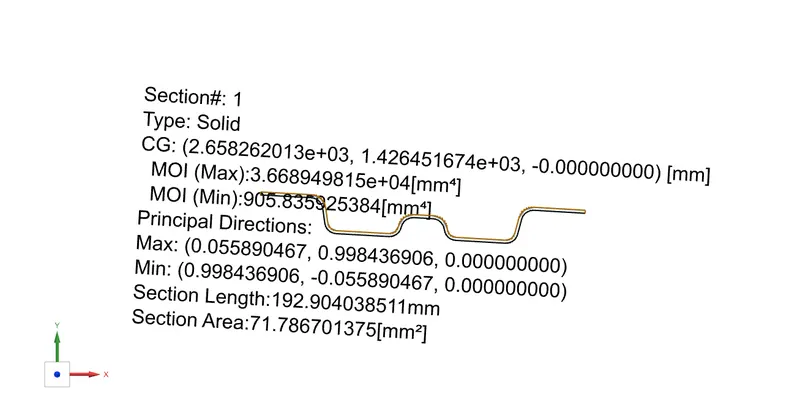
I=905 mm^4
Y= 80/2=40mm
S= I/Y= 905/40
S= 22.5 mm^3
REAR ROOF RAIL:
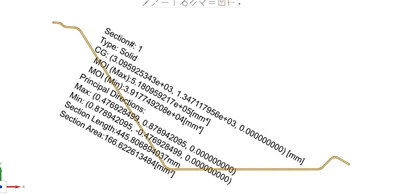
S=I/Y
I= 39177 mm^4
Y= 191/2
=95.5 mm
S= 39177/95.5
=410.2 mm^3