Roof challenge
Aim:- the Given Roof styling, create an ASSEMBLY by developing the essential flanges for the outer roof and creating the reinforcements.
Provide appropriate dimensions and check for Draft analysis.
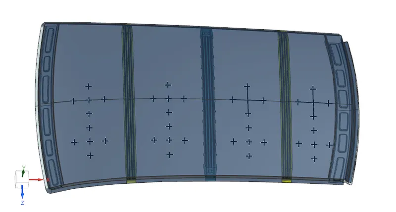
Do a curvature study on the roof and perform calculations to determine the position of the Bow-roofs.
Introduction
Roof:-
An automobile roof or car top is a BIW portion of an automobile that sits above the passenger compartment, protecting the vehicle occupants from sun, wind, rain, and other external elements.
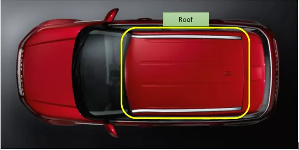
The types of roofs are:
- Convertible roofs
- Hardtops
- Sunroofs
- T-tops
- Targa tops
- Vinyl roofs
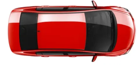
Hardtops -
When we talk about hardtops, we refer to the common rigid forms of automobile roofs we see around. This type of roof is made from metal or plastic in modern-day cars. So, the common Toyota Corolla, Camry, and many of the cars in Nigeria are all Hardtops.
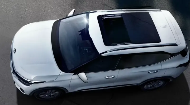
Sunroof -
A sunroof is an operable type of roof that allows for an opening in the roof of an automobile; say a window in a roof. It can allow either light or air or both to enter the vehicle. They are either operated manually or automatically.
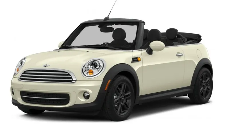
Convertibles -
convertibles are passenger cars that can be driven with or without the entire roof in place. They have first introduced as open-air vehicles; no roofs, no sides.
Under the styling surface of the roof. Other structures contribute to its strength and stability. They are mainly installed on the flatter surface of the roof. The other structures that lie inside the roof are:
- Front roof rail - Front roof rail is used to provide strength to the roof panel and it also acts as a link between windshield glass, roof panel, and headliner. Headroom clearance and visibility criteria should be considered the important factor while designing the front roof rail
- Bow roof - Bow roofs are again the roofs that will provide support to the roof panel by increasing its strength. The position of the bow roofs is the very factor that needs to be considered. The bow roofs should be straight.
- Center roof rail - This is a roof rail that will at the center of the roof to provide strength and stability to the roof. The center roof rail will be a straight roof rail.
- Rear roof rail - Rear roof rail is again used to strengthen the roof and this acts as a link between the roof panel and the backglass which is connected to the backdoor of the car.
Types of Rollovers
- Tripped-NHTSA data show that 95% of single-vehicle rollovers are tripped. This happens when a vehicle leaves the roadway and slides sideways, digging its tires into soft soil or striking an object such as a curb or guardrail. The high tripping force applied to the tires in these situations can cause the vehicle to roll over. E.g. Soft soil, Guardrail, Steep Slope
- Un-Tripped -Un-tripped rollovers are less common than tripped rollovers, occurring less than 5% of the time, and mostly to top-heavy vehicles. Instead of an object serving as a tripping mechanism, un-tripped rollovers usually occur during high-speed collision avoidance manoeuvres.
For this reason, strength is very important criteria for designing vehicle roof.
FMVSS 216 Roof crush standards-
FMVSS 216, Roof Crush Resistance, establishes strength requirements for the passenger compartment roof of passenger cars, multipurpose passenger vehicles, trucks and buses with a GVWR of 2722 kilograms or less. The purpose of the standard is to reduce deaths and injuries due to the crushing of the roof into the passenger compartment in rollover accidents. The standard does not apply to school buses and passenger cars that conform to the dynamic rollover test requirements of FMVSS 208, Occupant Crash Protection, and S5.3 by means that require no action by passenger car occupants. It also does not apply to convertibles, except for optional compliance with the standard as an alternative to the rollover test requirements in S5.3 of FMVSS.
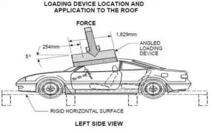
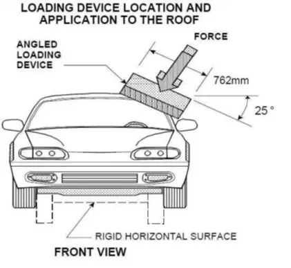
The prescribed static loading device is a rigid unyielding rectangular block 762 millimetres by 1,829 millimetres. It shall not move more than 127 millimetres to achieve the specified resistive load when applied to the forward edge of a vehicle’s roof – see Figures 1 and 2. The resistive load to be achieved is 1½ times the unloaded vehicle weight (UVW) of the test vehicle or 22,240 Newtons, whichever is less.
The force shall be applied in a downward direction perpendicular to the lower surface of the static loading device at a rate of not more than 13 millimetres per second until reaching the compliant resistive load. The test shall be completed within 120 seconds. The static loading device shall be guided throughout the test so that it moves, without rotation, in a straight line with its lower surface oriented as follows and as shown in Figures
Following are the design considerations of the roof-
- Visibility criteria
- Head clearance
- Heat distortion and snow load criteria
- Draft analysis
- Safety parameters
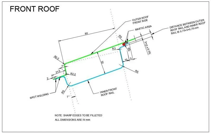
Master section
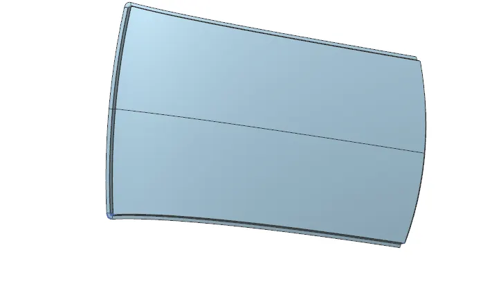
Roof
The ditch area of the roof is designed using the master sections provided
Front Roof Rail
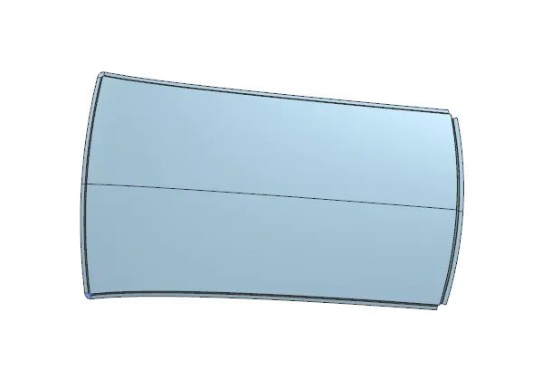
The Front rail is created according to the master section and keeping the visibility criteria in mind.
Front roof rail is used to provide strength to the roof panel and it also acts as a link between windshield glass, roof panel, and headliner. Headroom clearance and visibility criteria should be considered the important factor while designing the front roof rail.
Rear Roof Rail
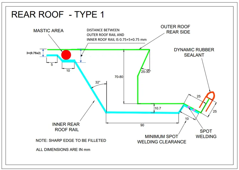
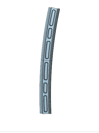
The Rear rail is designed keeping in mind the rear visibility criteria, and using the master section provided
Center roof rail:
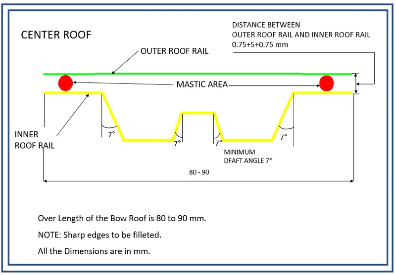
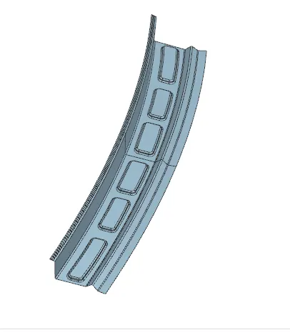
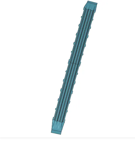
This is a roof rail that will at the center of the roof to provide strength and stability to the roof. The center roof rail will be a straight roof rail. The reinforcement of the rail is attached with the roof by Mastics and attached to the rail by spot welds. For the Mastics the reinforcement has a clearance of 5mm from the roof.
Bow Roof Rail 1 and 2
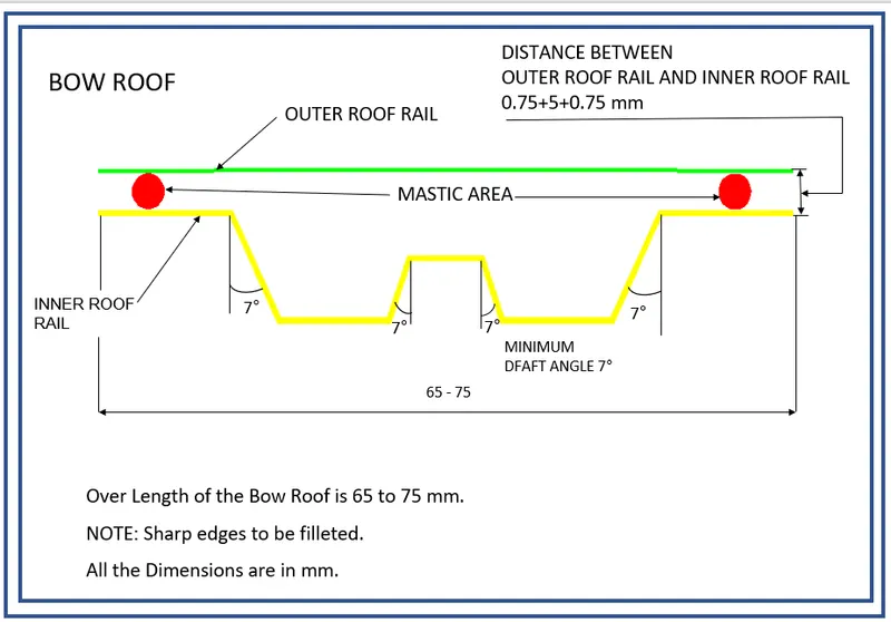
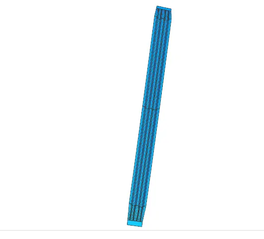
The bow roof rails also provide the roof with structural strength and their position have to be justified by the Heat Distortion and Snow Load criteria. Both the Bow Rails are attached to the roof by means of Mastics thus a clearance of 5mm from the roof is provided for that purpose. Bow roofs are again the roofs that will provide support to the roof panel by increasing its strength. The position of the bow roofs is the very factor that needs to be considered. The bow roofs should be straight.
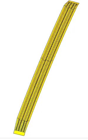
Draft Analysis-
Draft analysis for roof
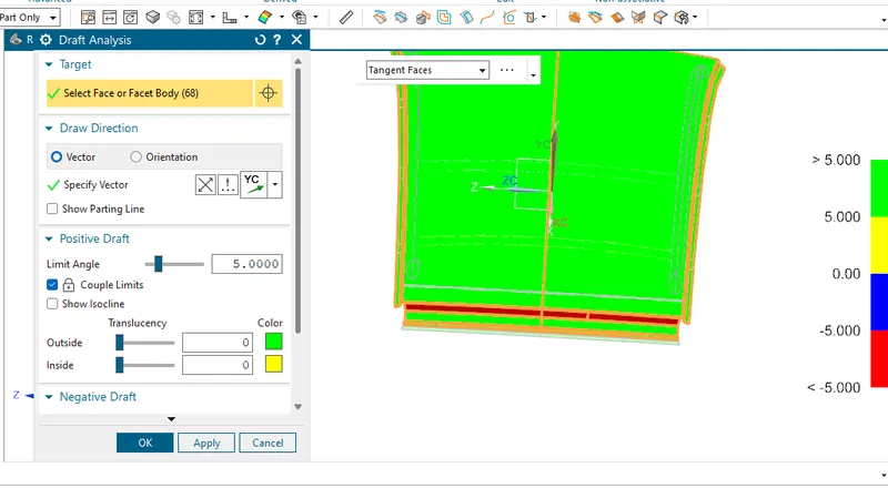
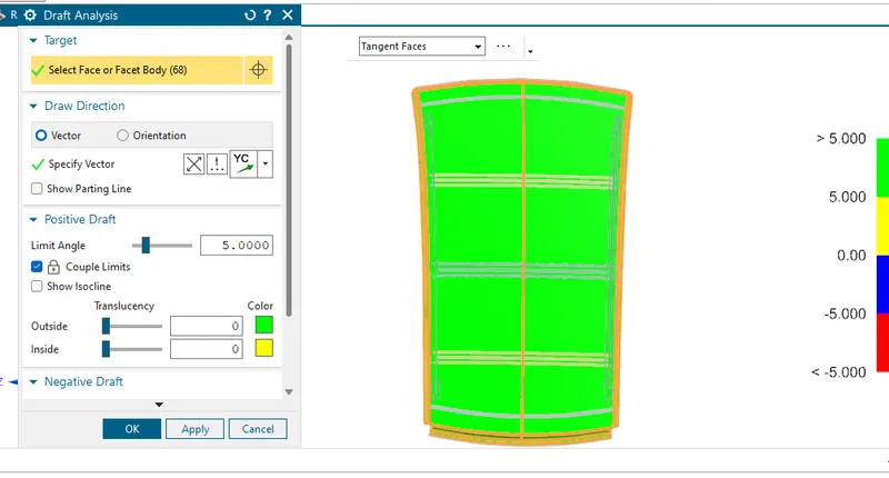
Draft analysis for Front roof rail
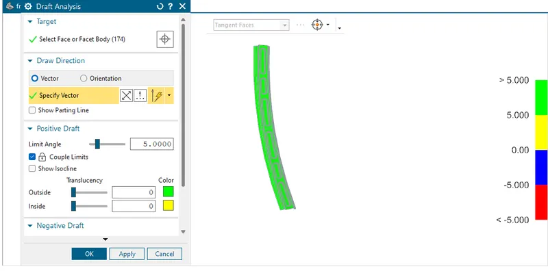
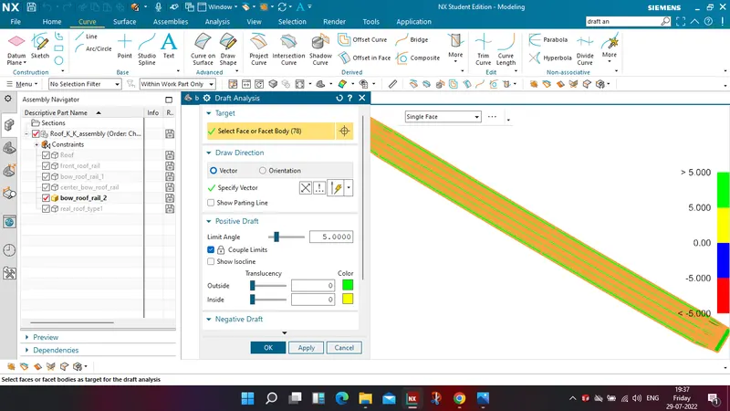
Draft analysis for Bow roof rail 1
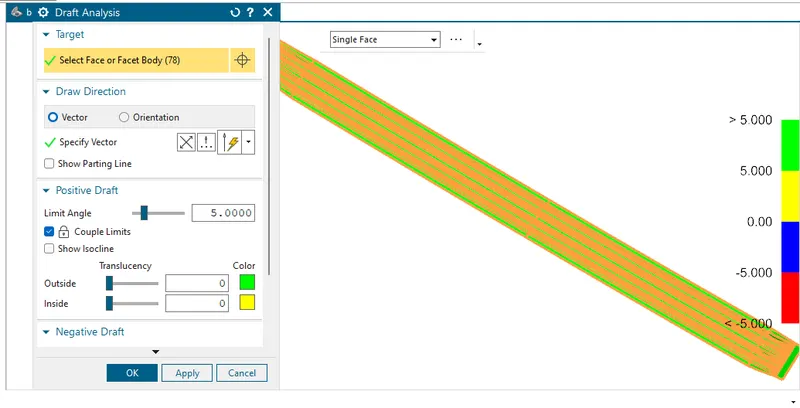
Draft analysis for Centre roof rail
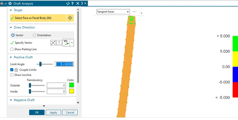
Draft analysis for Bow roof rail 2
Draft analysis for Rear roof rail
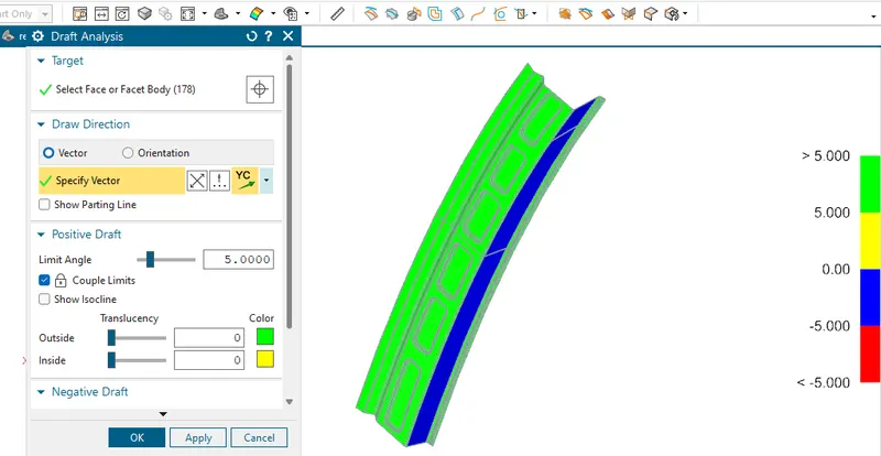
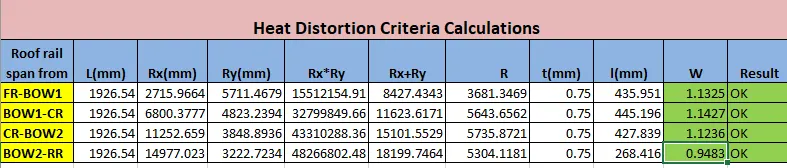
Bow–Roof Prediction Formula
W = [1.73 x 10^(-3) x L] + [1.85 x 10^(-8) x (R^2)/t] + [ 1.10x10^(-3) x l] - 2.68
Where,
L = Roof Length in X-Direction[mm](Roof dimension in 0-Y)
R = Roof curvature
R = 2(Rx*Ry)/(Rx+Ry)
Rx = X curvature
Ry = Y curvature
t = Roof plate thickness [mm]
l = Bow Roof Span [mm]
Snow load criteria calculations
Snow load criteria is useful to justify the bow roof rail position in snow fall regions. Due to snow fall snow will get collected on the top roof which will tend to bend the roof. Bow roof will be at such position which will provide more strength to roof against bending.
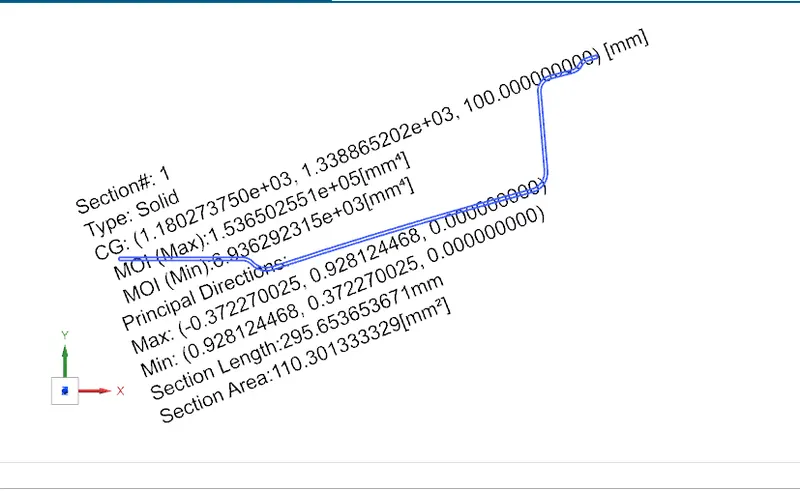
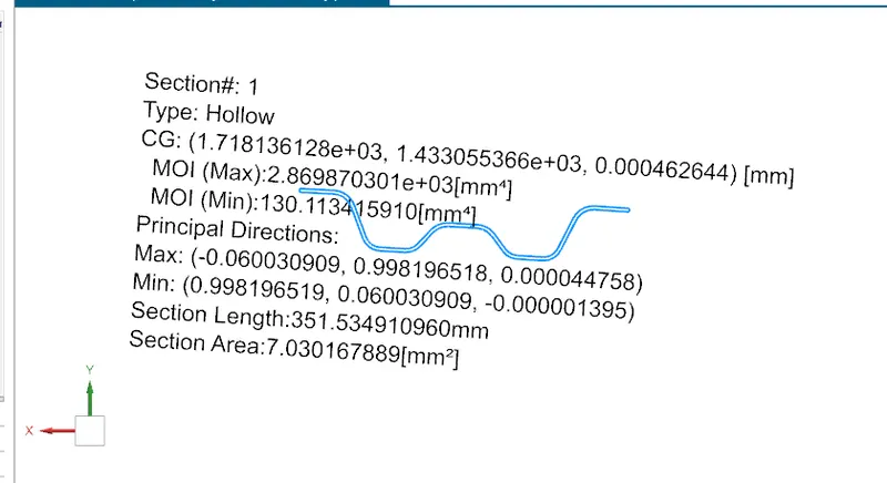
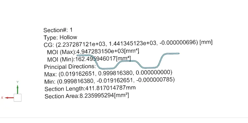
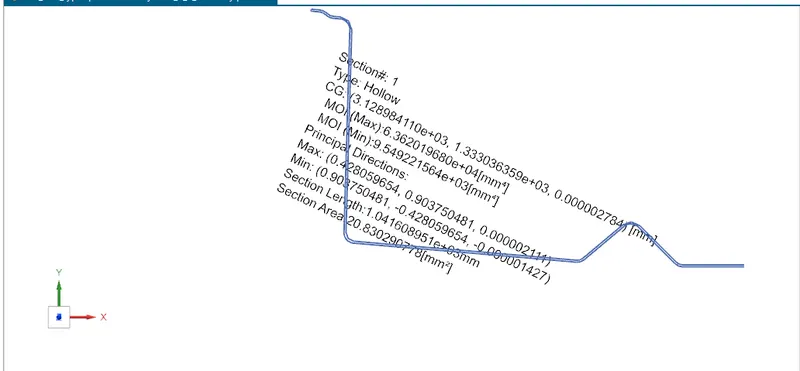
Qr = [Iy x t2] / [α x s x [(Rx + Ry)/2]2 x 10-8]
Note: The Qr value given over here is correct. There was a typo error in the formula given in the video.
Where
α = My x Lx2 x 10-12 , My = Y(Ly-Y)
Judgement condition = Qr ≥ 3.1
250 ≤ s ≤ 380
t = Roof plate thickness [mm]
Ly = Distance between the front and rear roof Rails on the Vehicle along with 0Y[mm]
Length of Roof panel with the center point between Roof rail Front /Rear as the reference point of the front and the rear.
Lx = Distance between the Left and Right end of the roof on the Roof BOW [mm]
Width of the roof panel exposed on the surface.
Y = Distance front Front Roof Rail to Roof BOW[mm]
s = Distance for which Roof BOW bears divided load [mm]
s = L1/2 + L2/2
Iy = Geometrical moment of inertia of Roof BOW (Y cross-section )[mm4]
Rx = Lateral direction curvature radius of roof panel Y cross-section on Roof BOW [mm]
Roof panel curvature Radius of the Length Lx in Front view
Ry = Longitudinal Direction curvature radius of the Roof panel X cross-section on Roof BOW [mm]
Roof panel X curvature radius of length s in Side view

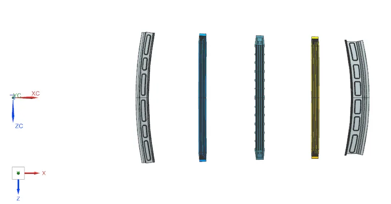
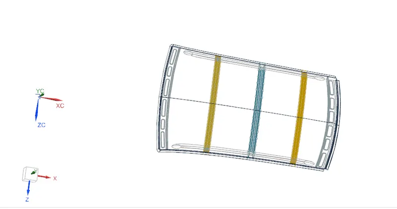
Roofs all parts:-
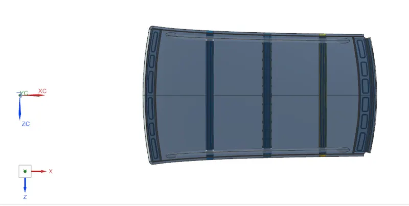
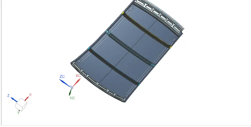
Conclusion:-
- Using all input data we have successfully designed Ditch area flanges, Front roof rail, Bow roof rail 1&2, Rear roof rail as per the requirement
- As per heat distortion criteria we come to know all bow roof positions are OK
- As per Snow load criteria we come to know there is improvement required
- All roof rails draft analysis are found OK