Roof challenge
ROOF DESIGN
Aim: Design and study the roof curvature using NX-CAD
OBJECTIVE:
- The objective of this project is to design a car roof with essential flanges and reinforcements like ditch area, front roof rail, bow roofs, central roof rail, and rear roof rail for the given styling surface
- Perform a curvature study on the roof and perform the distortion and snow load criteria calculations termini whether the bow roofs are at the correct positions.
- To find a moment of inertia and section modulus for Bow roofs and central roof rail. Front roof rail and rear roof rail.
- Perform the draft analysis for each reinforcement
SOFTWARE USED:
NX –CAD
INTRODUCTION:
The car top is the portion of an automobile that sits above the passenger compartment, protecting the vehicle occupants from sun, wind, rain, and other external elements. The roof panel is the section of material, usually sheet metal that forms the roof of a vehicle. Its long, low hood was impressive, as was the flat roof panel.
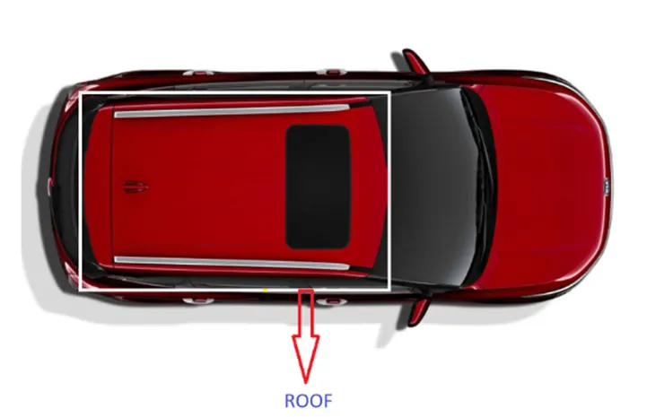
There are at least three types of roofs commonly installed on cars, namely sunroofs, moon roofs, and also panoramic roofs. Sunroofs are often even called moon roofs. The three are different in terms of use and benefits.
The famous Roof Types in the Market:
- Hard Tops: A rigid form of Roof, typically constructed from metal.
- Sunroofs: An operable window in a Roof, which allows light or fresh air into the car compartment.
- Convertible: This allows an open-air driving experience, with the ability to provide a when required.
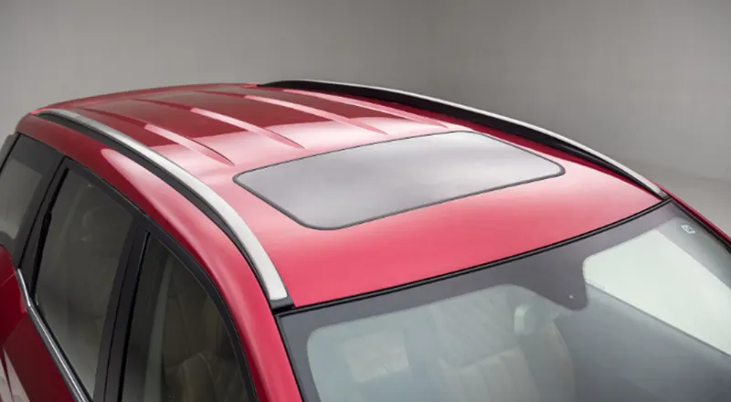
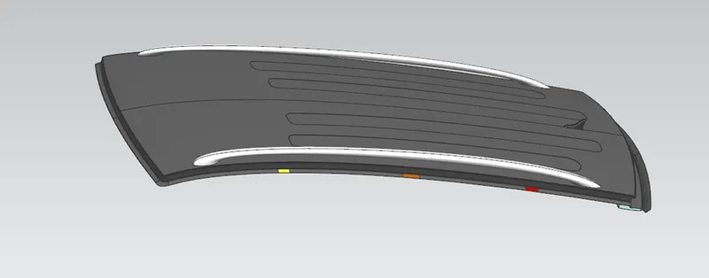
The roof is a styling surface part that is fixed with the BIW body through the rails and panels inside the upper roof to provide it with strength and stiffness. The Ditch area plays an important role here to fix the reinforcement on the component. The rails and reinforcements are joined to the ditch area with a spot weld where it's not the styling part. The required tool opening angle is a minimum of 3 Degrees.
Factors which is considered before creating a Ditch area,
- Headroom clearance
- Visibility criteria
- Back door assembly
- Windshield assembly
DESIGN OF ROOF AND REINFORCEMENTS
For this project, an A-surface along with the roof rails will be provided and the Roof ditch area along with the Front, Rear Centre, and Bow Roof Rails are to be designed
Certain critters are to be followed to design the above parts
Design criteria to be followed:
- Material Selection
Material selection plays an important part in designing any part. The material for a part is selected keeping in mind the tensile strength, bending, static and dynamic loading that the part would be subjected to. Materials used for the roof and its different reinforcements are mentioned below.
- Roof: SP121AQ T0.7
- Front Roof Rail: SP783AJQ
- Rear Roof Rail: SP783AJQ
- Bow Roofs: SP121BQ
- Centre Roof: SP153-98OPQ
- Visibility Criteria
The visibility criteria of a driver is one of the most important factors when designing the roof. The roof should be designed such that it does not hinder the visibility range of the driver. The ditch area of the roodesignedesign keeps this criterion in mind.
- Head Clearance
This factor is considered when designing the reinforcements of the roof. The reinforcements should be designed in a way that it provides ample headroom clearance for the occupants in the car and does not collide with the head in case the car moves over a bump It should not act as a hind toe for the driver’s rear visibility.
- Position of the reinforcements
The position of the reinforcements is governed by the below criteria.
- Heat distortion
This determines the temperature the roof structure can withstand. The value obtained from the heat distortion prediction formula should be less than 2.7 to be deemed fit for use.
- Snow load criteria
This factor is taken into consideration for areas with high snowfall which then sets on the car roof. This criterion measures the elasticity of the roof wherein the roof should come back to its original shape and form on the removal of the snow, which in this case acts as the load. The value Qr obtained for the snow load prediction formula should be greater than 3.1 for the design to quality being used.
- Drawibility
The roof and its parts are manufactured using a deep drawing process. For this reason, the designs should be manufactural and the design should have a positive draft angle for smooth surface build and also reduced induced stresses in various parts of the reinforcements.
REINFORCEMENTS:
If the roof is flat it is very weak and cannot able to withstand the forces like snow, so to increase the strength of the roof these reinforcements like front roof rail, central roof rail, rear roof rail, and bow roofs are introduced and joined to the flat surface of the roof with the different joining process
Different types of reinforcements that the car has are:
- Front roof rail
- Bow roofs
- Central roof rail and
- Rear roof rail
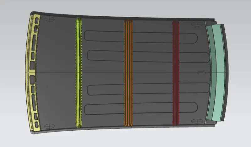
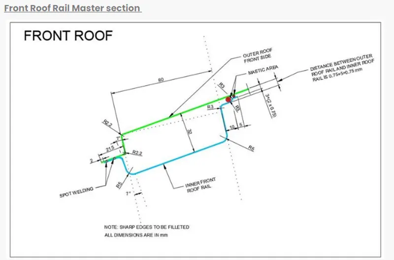
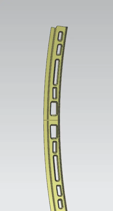
FRONT ROOF RAIL: The front roof rail is the one that joins the windshield glass, the body side outer, and the inner panel also. Here the front roof rail is designed based on the master section given
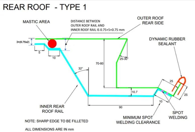
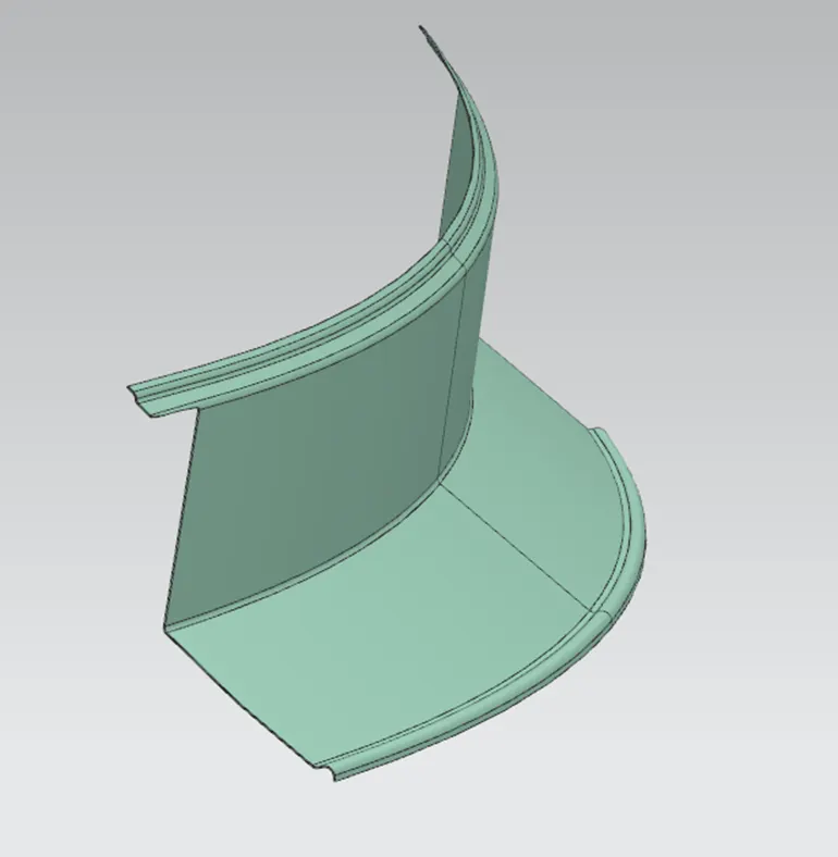
REAR ROOF RAIL: The rear roof rail is the one that joins the back door and the body side outer
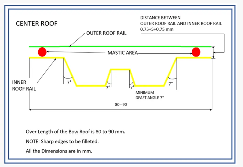
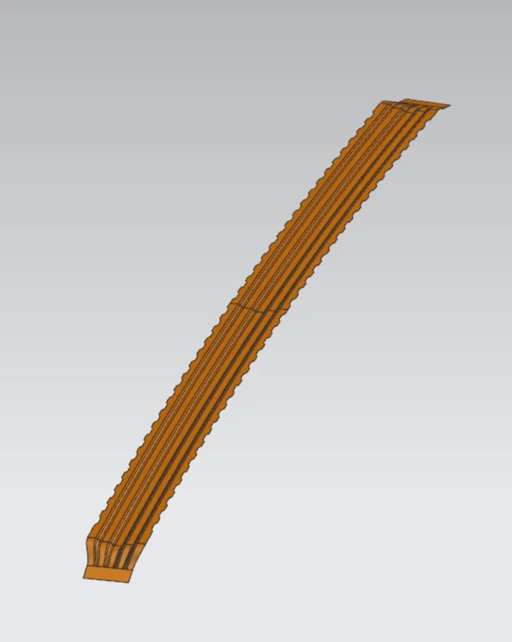
CENTRAL ROOF RAIL: Central roof rail helps in providing effective support to the flat area of the roof as it is more susceptible to failure under the action of load. Generally, a central roof rail is placed at the center of the roof which is connected to the B-pillar support structure. This central roof rail helps in adding strength to the roof during the roll-over test.
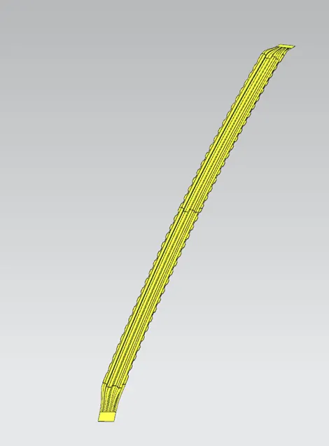
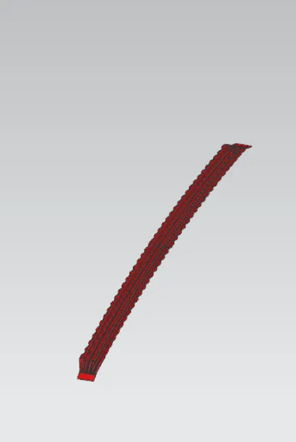
BOW ROOFS: The bow roofs are given to improve the torsional stiffness and load-bearing capacity of the roof structure. The number of bow roofs presents depends on the overall size of the roof. Presently in this project, two bow roofs are added.
JOINING PROCESS: Mastics are introduced between the roof outer panel and the reinforcements for joining. Where ever the mastic is introduced there is a remarkable improvement in the strength Spot welding is also introduced to join the reinforcements and the outer panel
ROOF CURVATURE STUDY
This is the study to justify the Bow roof positions in the Roof design are correct or not. To validate the positions of the bow roofs we have two different load condition studies. The current Roof design should pass these conditions so that it passes the requirements. The two conditions are as mentioned below. They are
1. Heat Distortion criteria.
2. Snow load criteria.
Heat Distortion criteria.
W = [1.73x10^-3 x L]+[1.85x10^-8 x (R^2)/t] +[ 1.10x10^-3 x l]-2.68
Judgment Condition: OK<2.7mm<NG
Where
L = Roof Length in X-Direction [mm] (Roof dimension in 0-Y)
R = Roof curvature
R = 2(Rx*Ry) / (Rx+Ry)
Rx = X curvature
Ry = Y curvature
t = Roof plate thickness [mm]
l = Bow Roof Span [mm]
As per the above formula when we calculated the results are as follows.
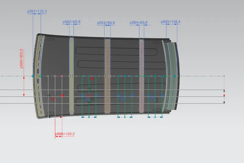
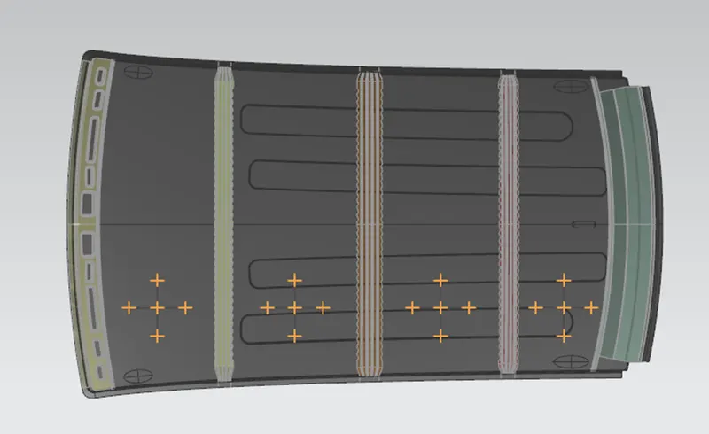
By projecting the point the s on roof surround face then calculating curve radius Rx and Ry
|
|
|||||||||||||||
| Heat | Distortion | criteria. | |||||||||||||
| sr.no | Bow Roof | RX (mm) | RY (mm) | Rx*Ry | 2*Rx+Ry | Rx+Ry | R (mm) | l (mm^4) | L (mm) | t (mm) | R^2/t | w cal | w thero | OK/NG | |
| 1 | FR & 1 st | 2608.03 | 5735.6705 | 14958800.73 | 10951.7305 | 8343.701 | 1.312574738 | 411.6 | 2061.8278 | 0.75 | 2.297136591 | 1.339722136 | 2.7 | OK | |
| 2 | 1st & CTR | 232338.5132 | 932.7467 | 216712981.5 | 465609.7731 | 233271.3 | 1.99600145 | 444.8 | 2061.8278 | 0.75 | 5.312029053 | 1.376242192 | 2.7 | OK | |
| 3 | CTR & 2 nd | 6004.7895 | 952.76616 | 5721160.234 | 12962.34516 | 6957.556 | 1.863060217 | 418.2 | 2061.8278 | 0.75 | 4.627991165 | 1.34698218 | 2.7 | OK | |
| 4 | 2nd & RR | 30097.03 | 1410.8212 | 42461527.98 | 61604.8812 | 31507.85 | 1.955223186 | 322.7 | 2061.8278 | 0.75 | 5.097196942 | 1.241932188 | 2.7 | OK |
RESULT- According to calculation all bow roofs pass the heat Heat Distortion criteria
2. Snow load criteria.
A crucial design criterion that is very important in the usable life of a vehicle. In the colder regions of the world where it snows heavily during winters and is prone to storms, the snow accumulated on the roof of a standing/parked vehicle may cause permanent damage. The support structure of the roof that is the roof bows and center roof reinforcement should be placed suitably such that it could withstand the weight of the snow. Instead of making the roof rigid and heavy which will cost more and would make the vehicle less fuel efficient, it is allowed to flex up to a limit that absorbs a bit of the energy similar to a spring. When the snow is cleared and there is no more load on the roof by design it should regain its original position.
As per Snow Load Prediction Formula
Qr = [Iy x t2] / [α x s x [(Rx + Ry)/2]2 x 10-8]
Judgment condition
Qr ≥ 3.1
250 ≤ s ≤ 380
here,
α = My x Lx2 x 10-12 , My = Y(Ly-Y)
t = Roof plate thickness [mm]
Ly = Distance between the front and rear roof Rails on the Vehicle along with 0Y[mm]
Length of Roof panel with the center point between Roof rail Front /Rear as the front and rear reference point.
Lx = Distance between the Left and Right end of the roof on the Roof BOW [mm]
The width of the roof panel is exposed on the surface.
Y = Distance front Front Roof Rail to Roof BOW[mm]
s = Distance for which Roof BOW bears divided load [mm]
s = L1/2 + L2/2
Iy = Geometrical moment of inertia of Roof BOW (Y cross-section )[mm4]
Rx = Lateral direction curvature radius of roof panel Y cross-section on Roof BOW [mm]
Roof panel curvature Radius of the Length Lx in Front view
Ry = Longitudinal Direction curvature radius of the Roof panel X cross-section on Roof BOW [mm]
Roof panel X curvature radius of length s in Side view
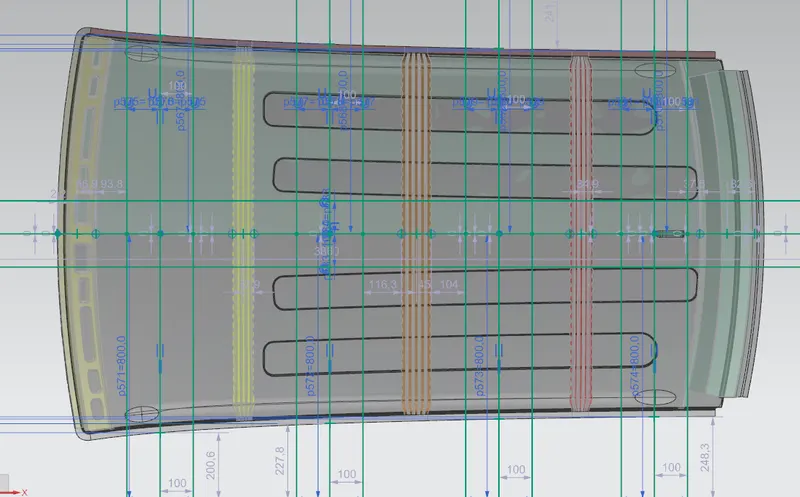
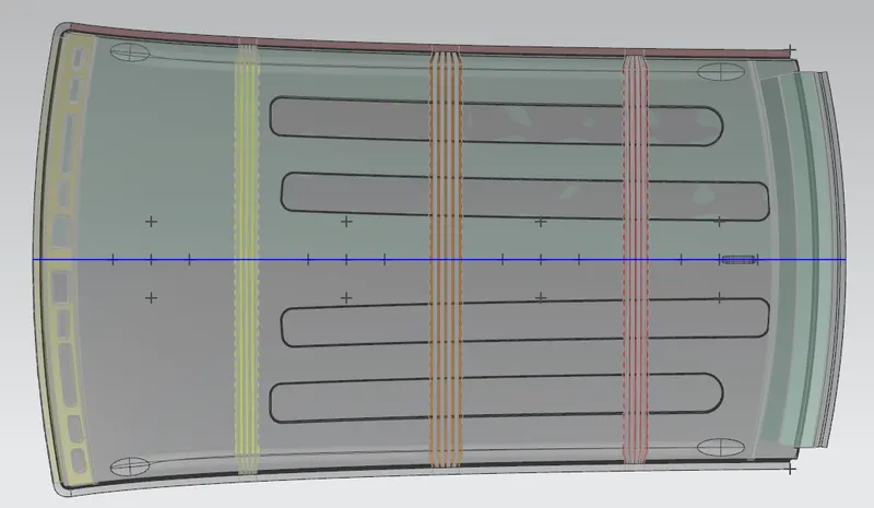
To calculate Rx & Ry we offset the y0 line 100mm on both sides from the center and create a point between the resp bow roof and offset by 100 mm after that project the point on the roof face
| Snow load criteria Calculations | |||||||||||||||
| sr.no | Bow Roof | MI(IY) | MY | α | Lx | Ly | L1 | L2 | y | S | RX (mm) | RY (mm) | t | Qr | Result |
| 1 | FR & 1 st | 875.96 | 782398.4989 | 1.123838964 | 1198.5 | 2061.8278 | 501.4 | 522.6 | 501.4 | 512 | 4545.618 | 2577.33 | 0.75 | 6.75107914 | OK |
| 2 | 1st & CTR | 892.211 | 804400.4483 | 1.053300038 | 1144.3 | 2061.8278 | 522.6 | 498 | 522.6 | 510.3 | 3782.945 | 6443.5 | 0.75 | 3.571272991 | OK |
| 3 | CTR & 2 nd | 905.866 | 778786.2444 | 0.971509057 | 1116.9 | 2061.8278 | 498 | 474.8 | 498 | 486.4 | 4301.809 | 11455.809 | 0.75 | 1.737100405 | NG |
RESULT- According to Snow load criteria 1st and center bow roofs pass the criteria but bow Roof 2 failed & 250 ≤ s ≤ 380 s also not satisfing the condiation then we want to change our roof postion or otherwise to make the roof stronger we create embosses on the roof to strengthen the roof.
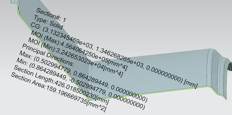
SECTION MODULUS STUDY OF THE SECTION OF THE ROOF RAILS:
The section modulus of the cross-sectional shape is of significant importance in designing structures. It is a direct measure of the strength of the structure
A structure that has a larger section modulus than another will be stronger and capable of supporting greater loads.
Section modulus (S) = I/y
Here,
I = Moment of inertia in (mm4)
y = Distance between the neutral axis and the end of the object (mm)
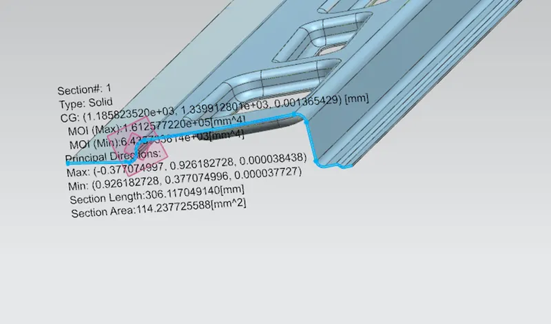
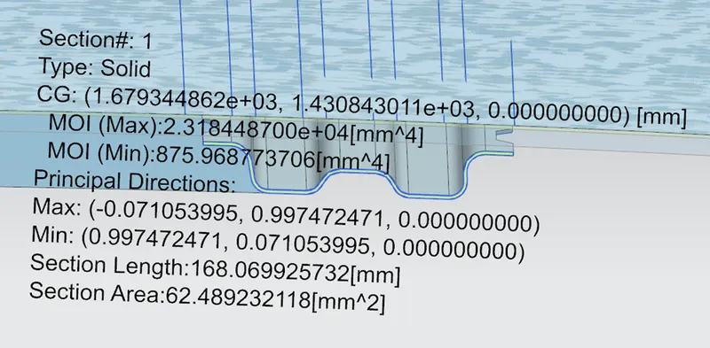
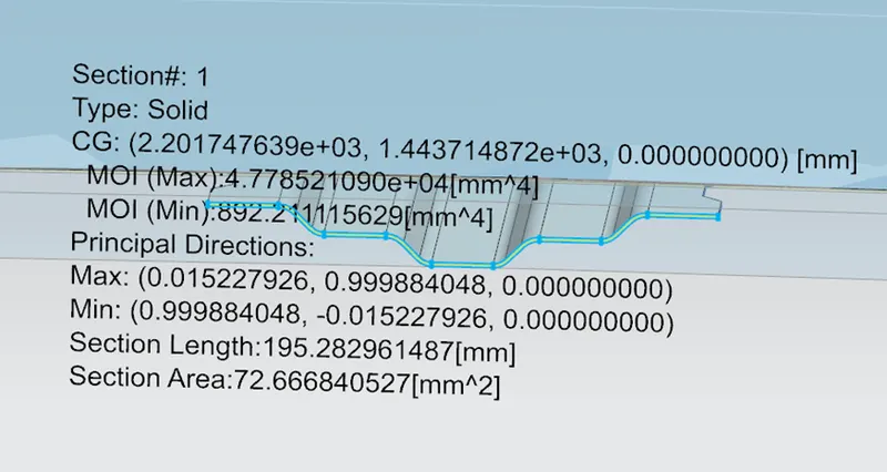
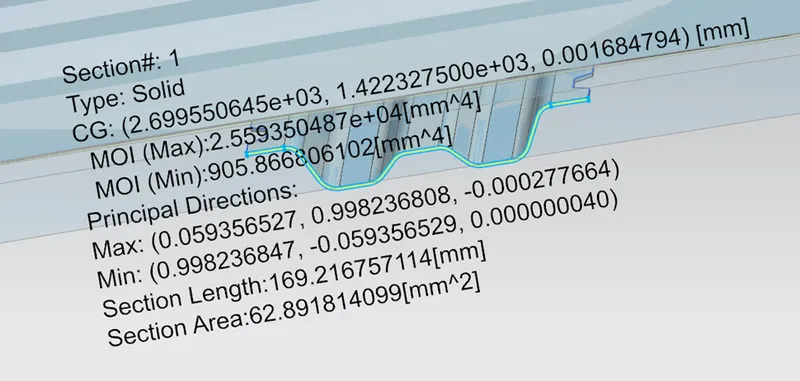
SECTION INERTIA ANALYSIS FOR EACH ROOF
| sr.no | Bow Roof | I(mm^4) | Y(mm) | Y/2(mm) | Section Modulas(s) |
| 1 | Front Roof | 6435.733 | 116.3 | 58.15 | 55.33734308 |
| 2 | 1st Bow Roof | 875.968 | 65.8 | 32.9 | 13.31258359 |
| 3 | Center Roof | 892.211 | 89.9 | 44.95 | 9.924482759 |
| 4 | 2nd Bow Roof | 905.86 | 69.8 | 34.9 | 12.97793696 |
| 5 | Rear Bow Roof | 3242.653 | 158.4 | 79.2 | 20.47129419 |
1. Front Roof
2. 1ST BOW Roof
3. Center Roof
4.2ND BOW ROOF
5. Rear Roof
DRAFT ANALYSIS:
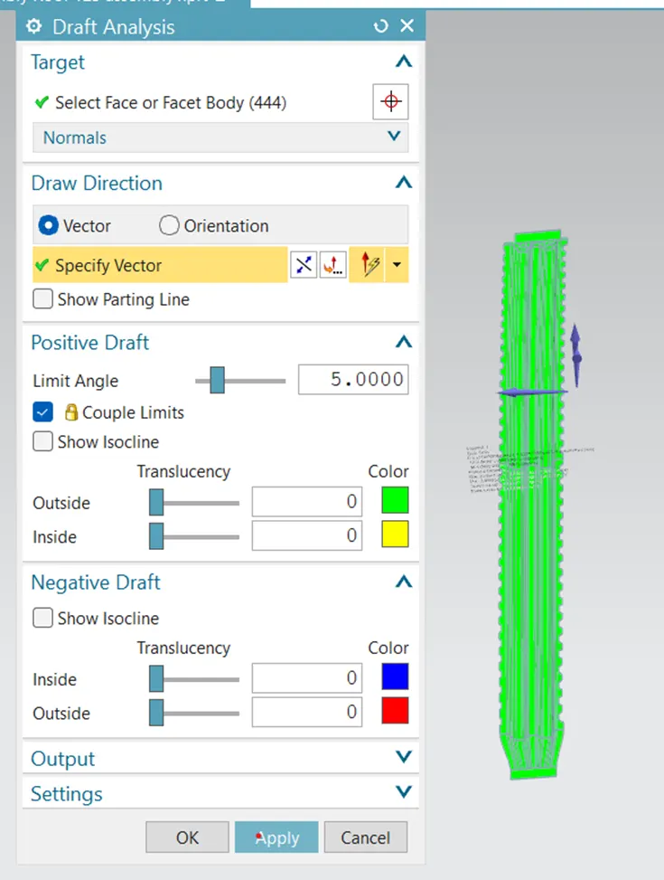
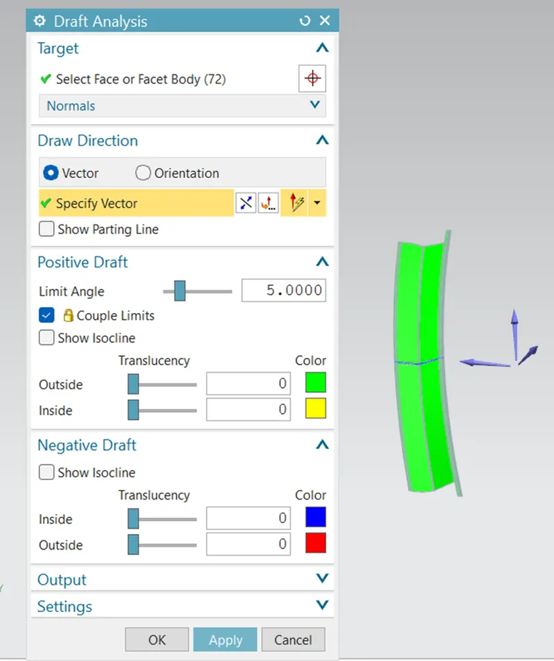
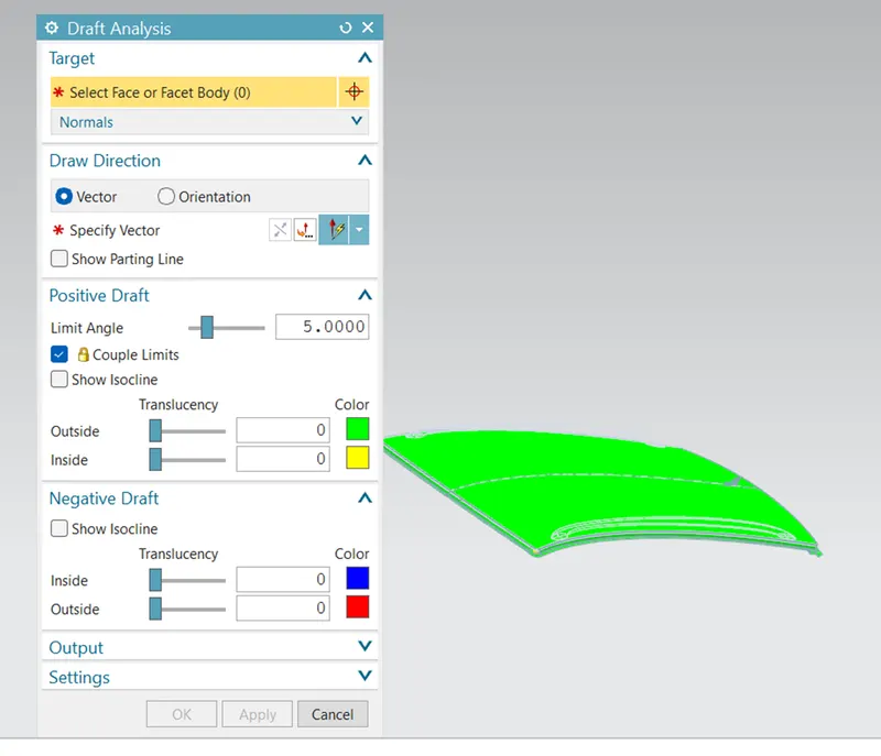
In NX to check whether the sheet metal part we have designed can be deep drawn, there is an option called draft analysis. This type of analysis is performed based on color ranges identifying zones on the analyzed element where the deviation from the draft direction at any point, corresponds to specified values. When the color is green it means it has a positive draft it means an area that is more than 3 degrees is shown as green. If it is shown in yellow that means it has less than 3 degrees and if in blue or red then it means it has a negative draft.
1. Front Roof
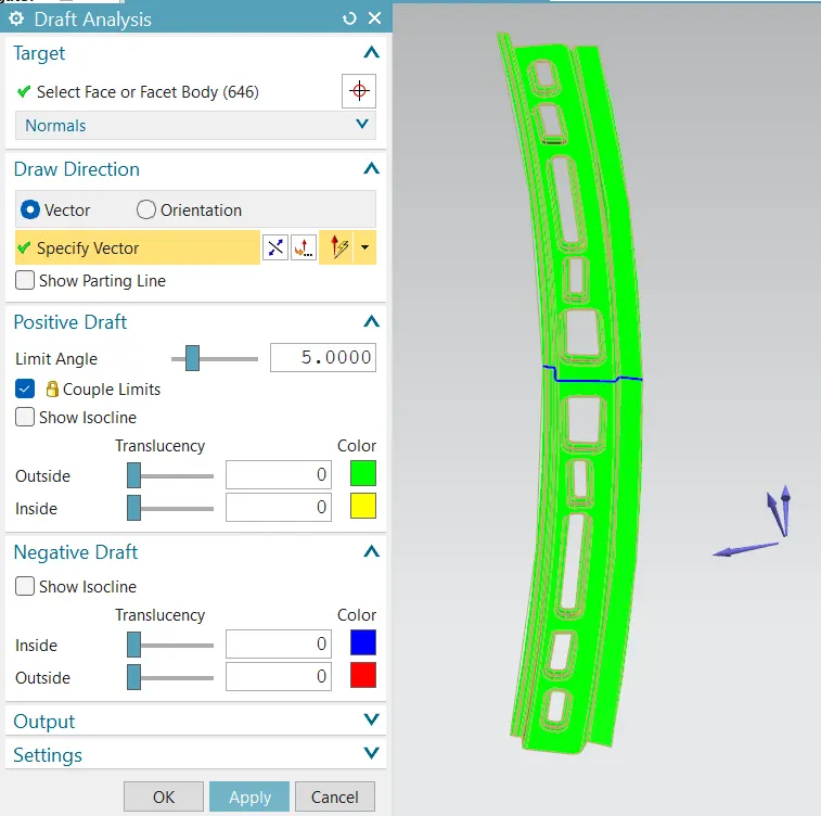
2. Bow Roof 1
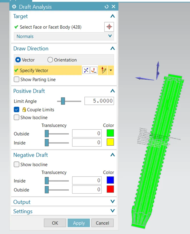
3. Center Roof
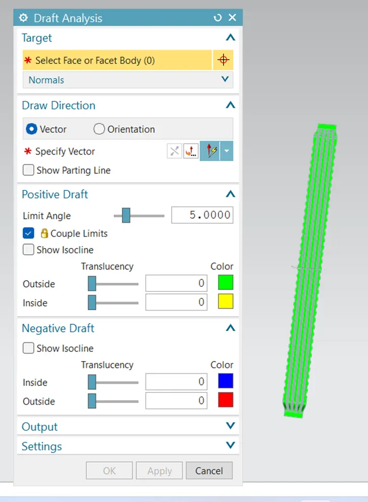
4. Bow Roof 2
5. Rear Roof
6. Roof Top Surface
RESULT
- According to calculation all bow roofs pass the heat Heat Distortion criteria
- According to Snow load criteria 1st and center bow roofs pass the criteria but bow Roof 2 failed
- 250 ≤ s ≤ 380 s also not satisfing the condiation then we want to change our roof postion or otherwise to make the roof stronger we create embosses on the roof to strengthen the roof.
- According to draft analysis all roof parts are in positive draft
CONCLUSION-
- The results obtained after doing a curvature study on the roof were adequate.
- The position of the bow roofs can be arranged better (over the flat areas) which helps in increasing the strength of the roof.
- Embossments are added to improve the strength & dynamics of the roof but can be avoided if not necessary as it increases the cost of manufacturing.
- We were successfully able to design the roof with all the roof rails for better support and strength.
- We designed it to satisfy the norms and regulations by calculating the heat distortion criteria and the snow load criteria. While doing this we also understood about the methodology behind designing the roof of the car and what we take into consideration while designing so.