Roof challenge
ROOF DESIGN
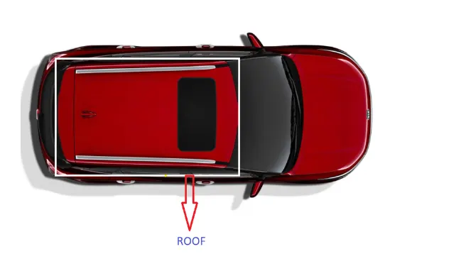
INDROUCTION:
An automobile roof is the portion of an automobile that sits above the passenger compartment, protecting the vehicle occupants from sun, wind, rain, and other external elements. Though it just looks like a styling surface that protects from sun, wind and other elements, various environmental conditions are taken into account for designing of the same. Roof should be provided with proper reinforcements for strengthening. Vehicle roof can be subjected to high heat conditions or load during snowy conditions. To make the roof withstand these conditions, various calculations are done. This ensures the safety of the passengers in the vehicle.
Design of any product starts from an requirement . The design engineer sketches the product based on the the requirement . Then the 2D sketch with the proper dimensions is converted into the 3D model using the advanced CAD software's . The another important thing in the design is that , every product that is designed should be able to manufactured . so the role of the design engineer is to design the product that can be easily manufactured and with less cost effective . This is the place where the Design for manufacturing [DFM] and Design of assembly [DFA] takes a role while developing any product . The process of development of design carries on until the design satisfies the customer needs .
OBJECTIVE:
- The objective of this project is to design car roof with essential flanges and reinforcements like ditch area , front roof rail , bow roofs, central roof rail and rear roof rail for the the given styling surface
- Perform a curvature study on the roof and perform the calculations for the heat distortion and snow load criteria to determine whether the bow roofs are at the correct positions.
- Finding moment of inertia and section modulus for Bow roofs , central roof rail . front roof rail and rear roof rail .
- Perform the draft analysis for each reinforcements.
WHY REINFORCEMENTS :
If the roof is flat it is very weak and cannot able to with stand the forces like snow , so in order to increase the strength of the roof these reinforcements like front roof rail, central roof rail, rear roof rail and the bow roofs are introduced and joined to the flat surface of the roof with the different joining process
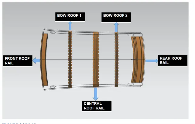
Different types of reinforcements that the car has are :
- Front roof rail
- Bow roofs
- Central roof rail and
- Rear roof rail
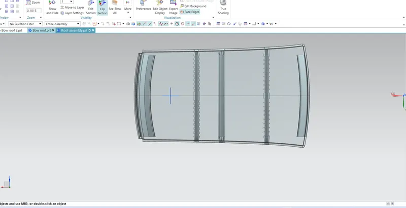
FRONT ROOF RAIL :
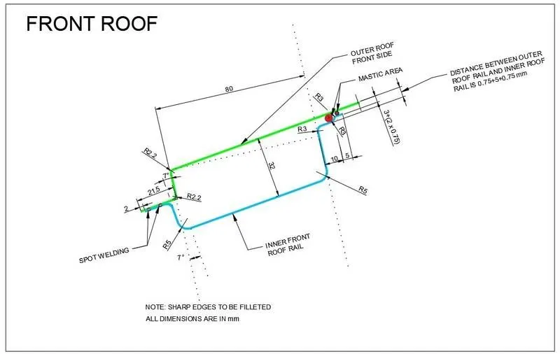
Front roof rail is the one which joins the wind shield glass , body side outer and the inner panel also. Here the front roof rail is designed based up on the master saection given.
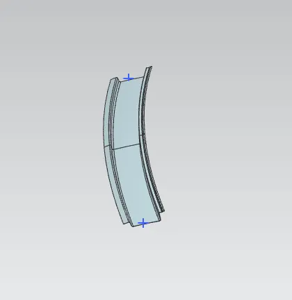
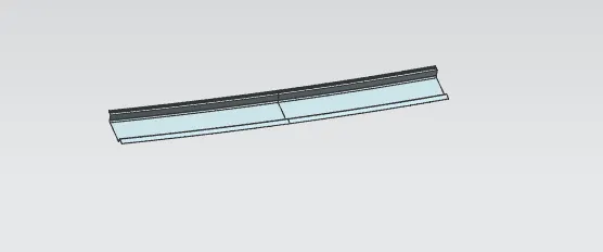
REAR ROOF RAIL :
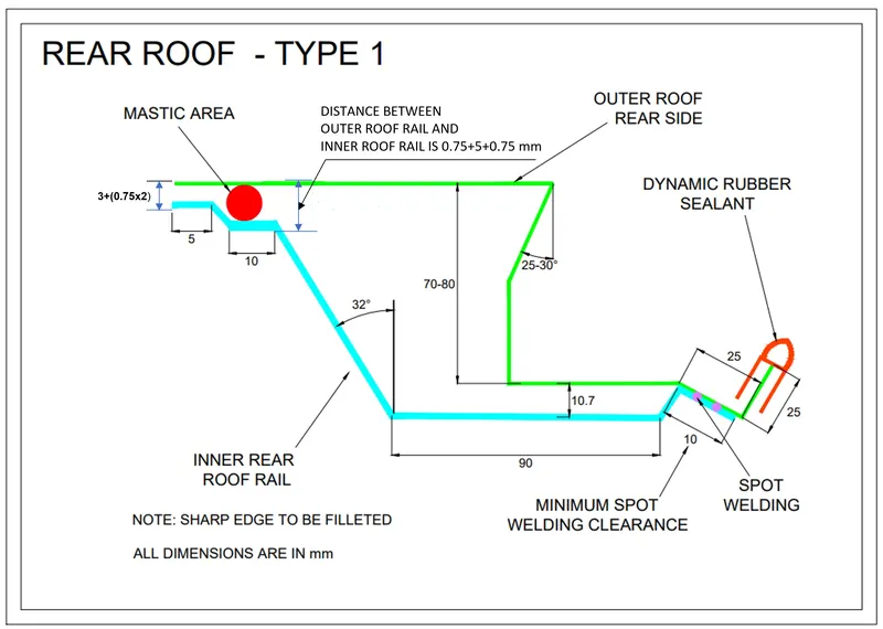
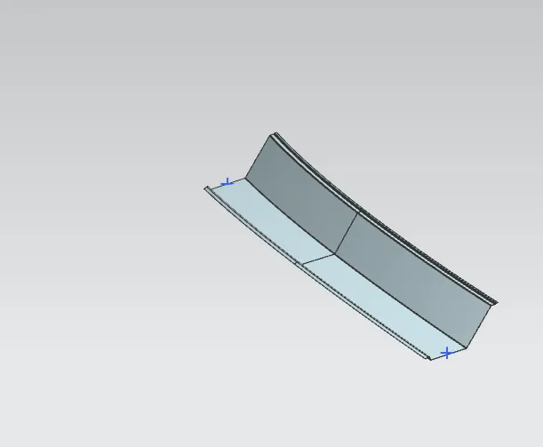
Rear roof rail is the one which joins the back door and the body side outer.
CENTRAL ROOF RAIL :
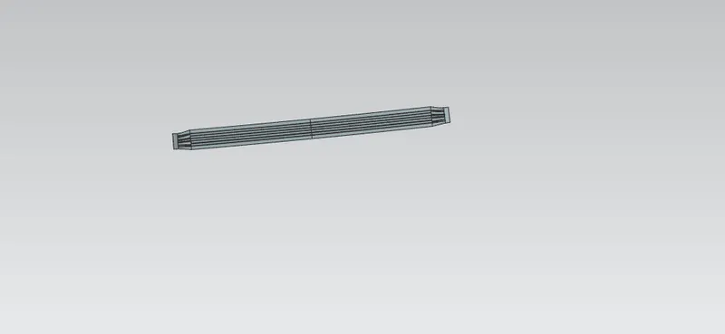
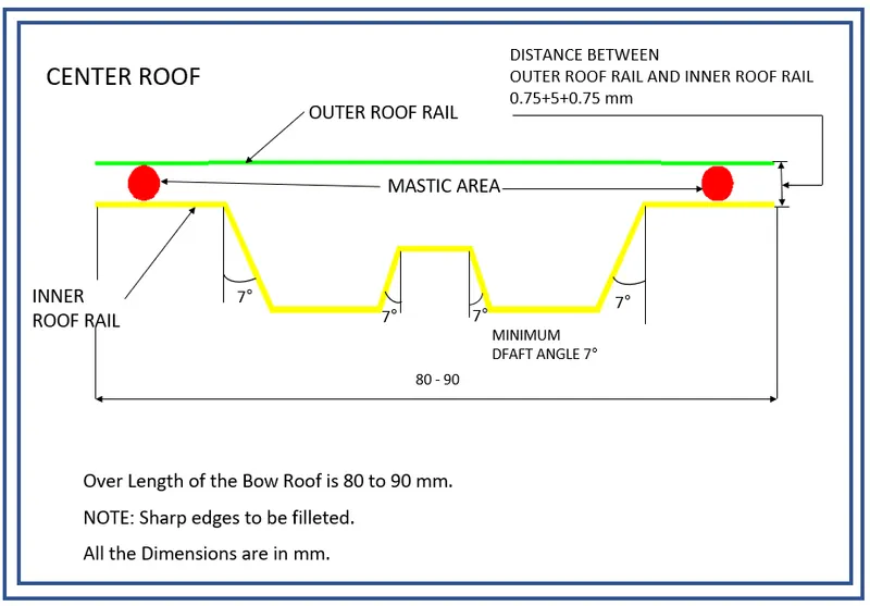
central roof rail helps in providing effectively support to the flat area of the roof as it is more susceptible to failure under the action of load . generally central roof rail is placed at the center of the roof which is connected to the B-pillar support structure . This central roof rail helps in adding the strength to the roof during the rool- over test.
BOW ROOFS :
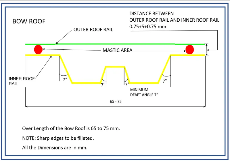
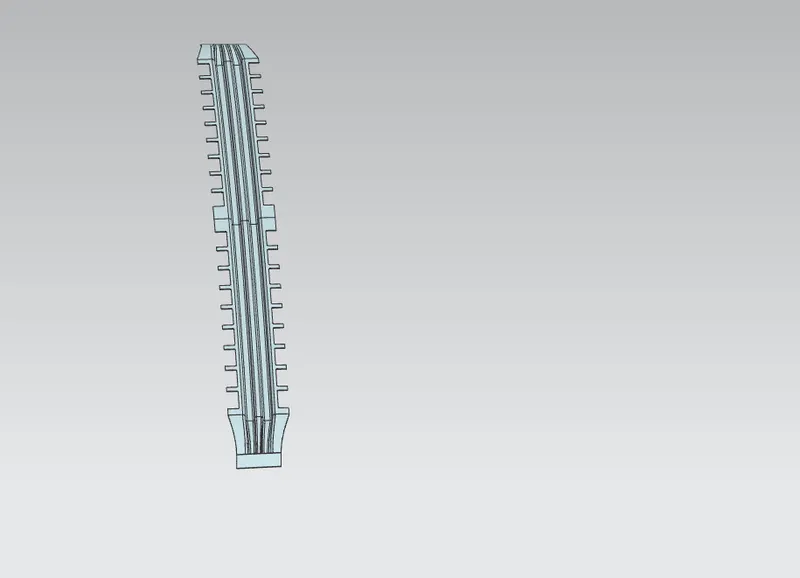
The bow roofs are give to improve the torsional stiffness and load bearing capacity of the roof structure . The number of bow roof present is depends on the overall size of the roof . Presently in this project two bow roofs are added.
CENTRAL ROOF RAIL WHEN SUNROOFN IS PRESENT:
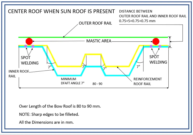
Reinforcement Center roof rail is effective support to the flat area structure roof. Because of center area of roof is more susceptible to failure under action of load. Usually, Reinforcement center roof rails are fixed at the center of the roof for connecting to the B – Pillar support structure, it will used for roll-over test.
Center bow roof and reinforcements are placed at the center of the roof structure. They two are connecting to help of spot - welding operation. Thickness of the Reinforcement center roof rail is 0.75mm.
JOINING PROCESS :
Mastics are introduced between the roof outer panel and the reinforcements for joining . where ever the mastic are introduced there is remarkable improve of the strength
Spot welding is also introduced to join the reinforcements and the outer panel.
DESIGN CONSIDERATION:
-
Visibility criteria
-
Head clearance
-
Curvature study
-
Hear distortion and snow load criteria
-
Draft analysis.
ROOF CRUSH TEST :
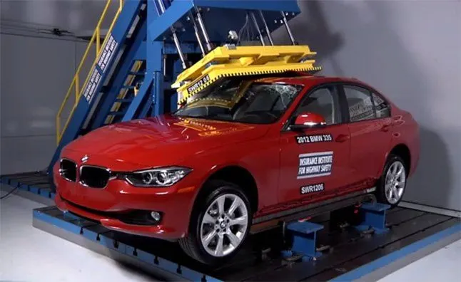
Roof crush test is the design given by the IIHS ( insurance institute of highway safety ) . After analyzing the many accidents IIHS has then fixed some regulations , that how to perform the crush test .
IIHS gives the rating based up on this test . For this they consider two points while giving the rating
- How fast the car can reforms to its original shape after the roll over and
- How deep is the protrusion after the roll over
Bow – roof prediction Formula
W = [1.73 x 10^(-3) x L] + [1.85 x 10^(-8) x (R^2)/t] + [ 1.10x10^(-3) x l] - 2.68
Where
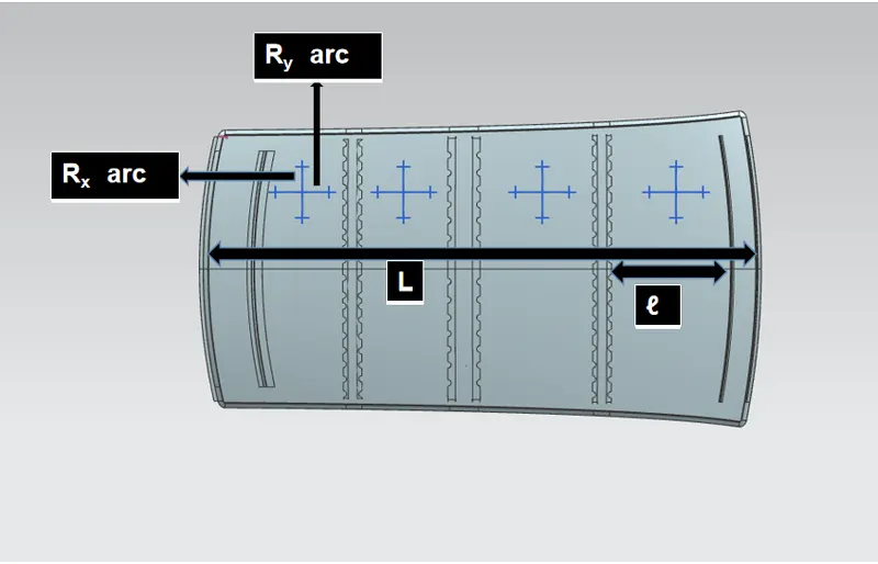
L = Roof Length in X-Direction[mm](Roof dimension in 0-Y)
R = Roof curvature
R = 2(Rx*Ry)/(Rx+Ry)
Rx = X curvature
Ry = Y curvature
t = Roof plate thickness [mm]
l = Bow Roof Span [mm]
Judgement Condition : OK< 2.7> 3.1
APPLY THE VALUES IN THE FORMULA :
In order to find the heat distortion apply all the necessary values from the roof to the give formula
CALCULATIONS :
GOAL OF ROOF CRUSH TEST :
To minimize the protrusion into the occupant compartment , so that the seat belts and air bags can do there job in protecting the occupant.
CONDITIONS TO FOLLOW FOR ROOF CRUSH TEST :
There are two conditions that should be followed for the roof crush test , they are
INITIAL CONDITION :
- Close and lock all the doors
- Close all the windows
SECOND CONDITION :
Fix the body sill or chassis frame on a hard lever surface horizontally
METHOD OF APPLYING THE FORCE :
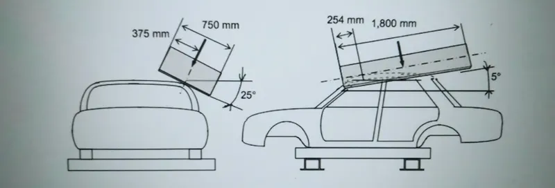
The load is applied in such a way that 50 is tilted from the front end to the rear end and the load will be in 1800 mm in length and 750 mm in width . The load is applied at the position of 250 from the flatness of the roof . The load is applied on the roof for almost 120 sec and the crush speed at which the load applied is 13 mm/sec or less than that
RESULTS :
If the displacements goes above the requirements level then we have to increase the bow roof thickness or add more mastics points to increase the strength . the stronger the roof the better it can protect the occupants in the roll over crashes.
Bow – roof prediction Formula
W = [1.73 x 10^(-3) x L] + [1.85 x 10^(-8) x (R^2)/t] + [ 1.10x10^(-3) x l] - 2.68
Where
L = Roof Length in X-Direction[mm](Roof dimension in 0-Y)
R = Roof curvature
R = 2(Rx*Ry)/(Rx+Ry)
Rx = X curvature
Ry = Y curvature
t = Roof plate thickness [mm]
l = Bow Roof Span [mm]
Judgement Condition : OK< 2.7> 3.1
APPLY THE VALUES IN THE FORMULA :
In order to find the heat distortion apply all the necessary values from the roof to the give formula
CALCULATIONS :

From the above table it can be concluded that all values of w<2.7 and also not w>3.1 so thus infers that current positioning of bow row are good in state as per design and found ok.
SNOW LOAD CRITERIA :
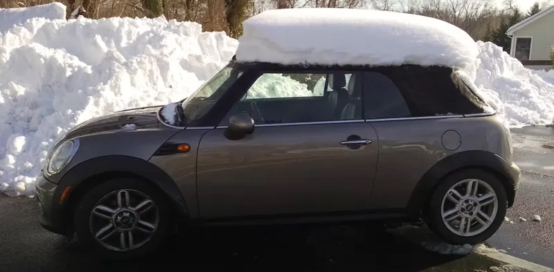
This test is done to know how is the roof behaving when there is a snow over . normally due to the snow weight the dent will happen. But the roof should be designed in such a way that when the snow is removal the roof should go it its original position . This is the basic requirements for snow load criteria .
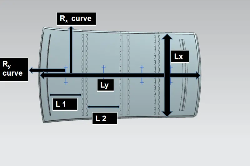
Qr = [Iy x t^2] / [α x s x [(Rx + Ry)/2]2 x 10-8]
Where
α = My x Lx2 x 10-12 , My = Y(Ly-Y)
Judgement condition = Qr ≥ 3.1
250 ≤ s ≤ 380
t = Roof plate thickness [mm]
Ly = Distance between the front and rear roof Rails on the Vehicle along with 0Y[mm]
Length of Roof panel with the center point between Roof rail Front /Rear as the reference point of the front and the rear.
Lx = Distance between the Left and Right end of the roof on the Roof BOW [mm]
Width of the roof panel exposed on the surface.
Y = Distance front Front Roof Rail to Roof BOW[mm]
s = Distance for which Roof BOW bears divided load [mm]
s = L1/2 + L2/2
Iy = Geometrical moment of inertia of Roof BOW (Y cross-section )[mm4]
Rx = Lateral direction curvature radius of roof panel Y cross-section on Roof BOW [mm]
Roof panel curvature Radius of the Length Lx in Front view
Ry = Longitudinal Direction curvature radius of the Roof panel X cross-section on Roof BOW [mm]
APPLY THE VALUES IN THE FORMULA :
In order to find the snow load criteria apply all the necessary values from the roof to the give formula
CALCULATIONS :

SECTION MODULUS :
Section modulus is a geometric property for a given cross-section used in the design of beams or flexural members. Other geometric properties used in design include area for tension and shear, radius of gyration for compression, and moment of inertia and polar moment of inertia for stiffness. Any relationship between these properties is highly dependent on the shape in question. Equations for the section moduli of common shapes are given below.
There are two types of section moduli :
The elastic section modulus and
The plastic section modulus.
The elastic section modulus is defined as
S = I / y
where :
S= Section modulus
I = second moment of inertia (or area moment of inertia, not to be confused with moment of inertia)
y = the distance from the neutral axis to any given fibre. It is often reported using y = c, where c is the distance from the neutral axis to the most extreme fibre.
BOW ROOF 1
Create an intersection curve with the help of the plane and select the bow roof 1
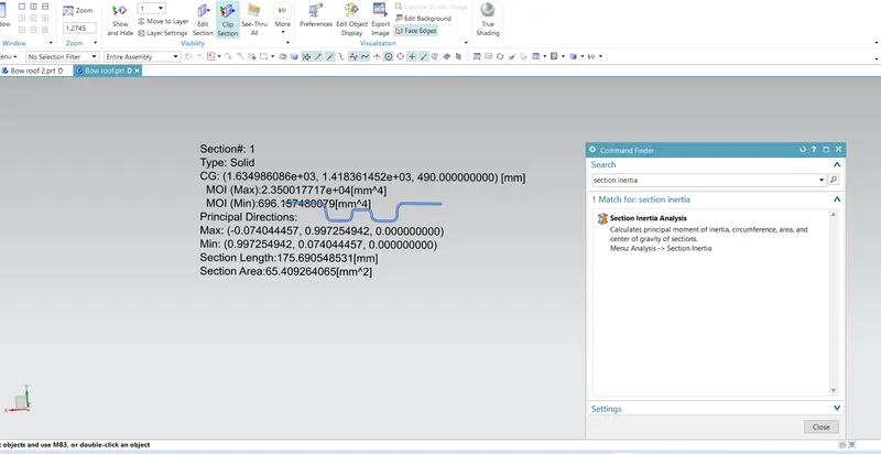
Moment of inertia maximum,( MAX) I max =2.3500 × 10⁴ ( mm4)
Moment of inertia maximum ,( MIN) I min =696.1574 x 10⁴ ( mm4)
SECTION MODULUS
S= moment of inertia /distance from the neutral axis to any given fibre
S = I / y
Y = 35 mm
FOR MAXIMUM MOI :
S= 2.3500 × 10⁴ ( mm4) / 44.81 mm
S max = 671.4286 mm3
FOR MINIMUM MOI :
S= 696.1574x10⁴ ( mm4)/ 44.81 mm
S min = 19.89021 mm3
BOW ROOF 2
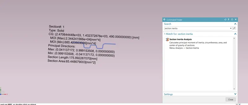
Moment of inertia maximum,( MAX) I max =2.344241566 × 10⁴ ( mm4)
Moment of inertia maximum ,( MIN) I min =685.423503086 x 10⁴ ( mm4)
SECTION MODULUS
S= moment of inertia /distance from the neutral axis to any given fibre
S = I / y
Y = 44.81 mm
FOR MAXIMUM MOI :
S= 2.3500 × 10⁴ ( mm4) / 35 mm
S max = 669.7833 mm3
FOR MINIMUM MOI :
S= 685.423503086x10⁴ ( mm4)/ 35 mm
S min = 19.58353 mm3
CENTRAL ROOF RAIL :
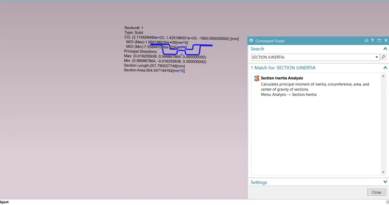
Moment of inertia maximum,( MAX) I max =1.660196030 × 10⁴ ( mm4)
Moment of inertia maximum ,( MIN) I min =7.5584410 x 10⁴ ( mm4)
SECTION MODULUS
S= moment of inertia /distance from the neutral axis to any given fibre
S = I / y
Y = 40 mm
FOR MAXIMUM MOI :
S= 1.660196030 × 10⁴ ( mm4) / 40 mm
S max = 415.049 mm3
FOR MINIMUM MOI :
S= 7.5584410x10⁴ ( mm4)/ 40 mm
S min = 415.049 mm3
FRONT ROOF RAIL:
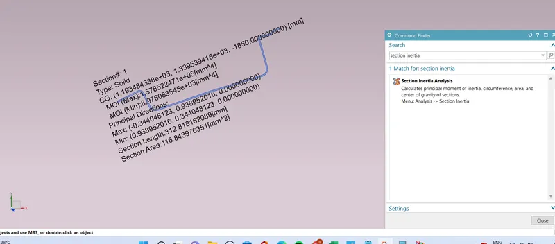
Moment of inertia maximum,( MAX) I max =1.578522471× 10⁴ ( mm4)
Moment of inertia maximum ,( MIN) I min =8.976083545x 10⁴ ( mm4)
SECTION MODULUS
S= moment of inertia /distance from the neutral axis to any given fibre
S = I / y
Y = 40 mm
FOR MAXIMUM MOI :
S= 1.578522471 × 10⁴ ( mm4) / 60.5 mm
S max = 260.9128 mm3
FOR MINIMUM MOI :
S= 8.976083545x10⁴ ( mm4)/ 60.5 mm
S min = 1483.65 mm3
REAR ROOF RAIL:
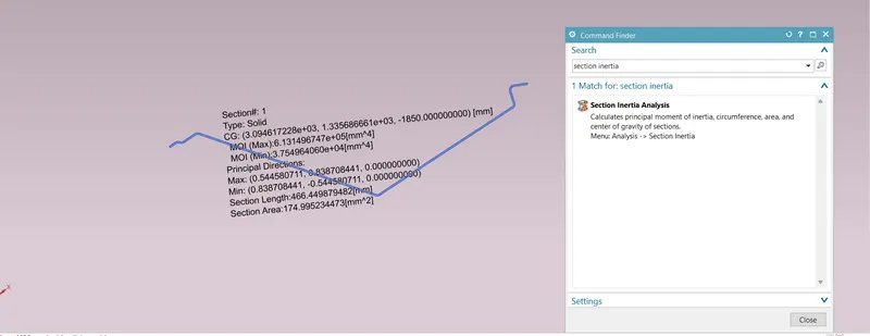
Moment of inertia maximum,( MAX) I max =6.131496747× 10⁴ ( mm4)
Moment of inertia maximum ,( MIN) I min =3.754964060x 10⁴ ( mm4)
SECTION MODULUS
S= moment of inertia /distance from the neutral axis to any given fibre
S = I / y
Y = 40 mm
FOR MAXIMUM MOI :
S= 6.131496747 × 10⁴ ( mm4) / 87.5 mm
S max = 700.7425 mm3
FOR MINIMUM MOI :
S= 8.976083545x10⁴ ( mm4)/ 87.5 mm
S min = 1025.838 mm3
DRAFT ANALYSIS :
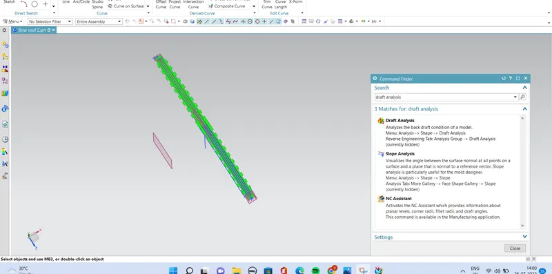
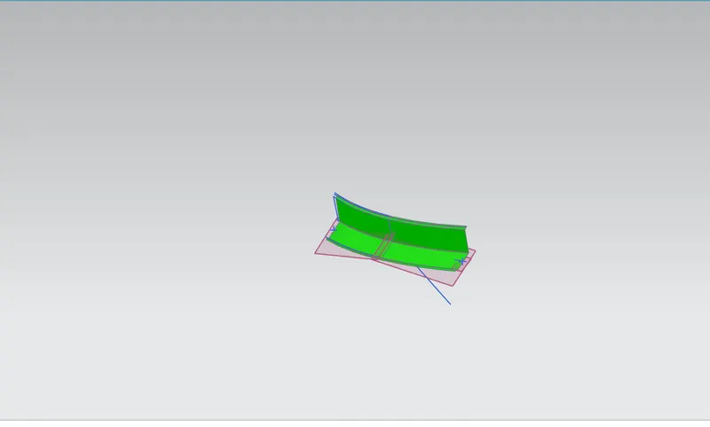
The Draft Analysis command enables you to detect if the part you drafted will be easily removed. This type of analysis is performed based on color ranges identifying zones on the analyzed element where the deviation from the draft direction at any point, corresponds to specified values.
Minimum draft angle of 70 is considered for analysis . green colour infer on the parts that all face along the tooling direction has positive draft angle greater than 70 and passed in analysis.
DRAFT ANALYSIS FOR FRONT ROOF RAIL :
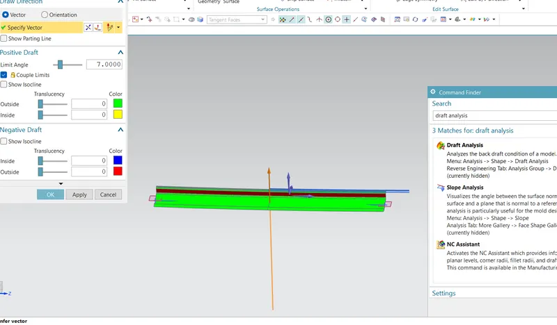
DRAFT ANALYSIS FOR BOW ROOF RAIL - 1:
DRAFT ANALYSIS FOR CENTRAL ROOF RAIL :
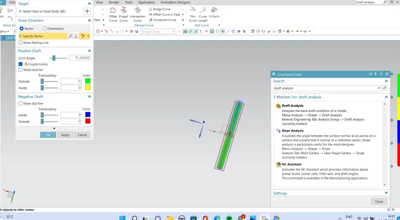
DRAFT ANALYSIS FOR BOW ROOF RAIL - 2:
DRAFT ANALYSIS FOR FRONT REAR ROOF RAIL :
MANUFACTURING TECHNIQUES:
The forming of sheet metal in a desired and attractive shape is a process thatrequires an understanding of materials, mechanics and manufacturing principles. Manufacturing a consistent sheet metal component is challenging dueto the nonlinear interactions of various material and process parameters. Oneof the major issues in the manufacturing of inconsistent sheet metal parts is
springback. Springback is the elastic strain recovery in the material after thetooling is removed and the final shape of the product depends on the springback amount formed. In this study according to the result of simulation theinverted compensation method is adopted to optimize die surface design. Similarly, to predict and compensate the springback error this study presentedan analytical approach of forming process in a stepwise modification of theautomobile roof panel. Moreover, based on Dynaform and finite elementanalysis of sheet metal stamping simulation the sprinback in automobile roofpanel is predicted and compensated. In addition, this study examines the significant requirements of the sheet metal forming precision of automobilebody and the simulation of forming, stamping and springback of automobile
roof panel is carried out, and the result of simulation also is analyzed.
The Design of Blank Shape and the Direction of Drawing:
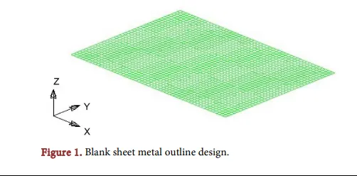
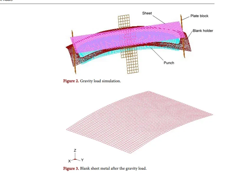
Most automobile panel shapes are complex and difficult to get through to startthe initial blank geometry shape. In addition, the geometric expansion factordoes not consider plastic deformation. Practically, variations in material properties, thickness distribution, blank dimensions, environmental conditions andspringback properties make the reproducibility and predictability of a blank
sheet metal forming process quite difficult.The selected part is relatively simple design using Dynaform to estimate thestock load and to get directly through the geometric shape of the initial blanksheet metal. The simplified rectangular blank sheet metal shape model shown in
Figure 1 has the maximum die size 30 cm, the smallest cell size 0.5 mm, and theoffset rate 0.05 mm mesh parameters.
In actual production, sheet metal (blank shape) is placed on the blank holderand the blank holder is the part that holds the sheet metal while the punch forceis applied. Punch is a curved and relatively large degree of bending force placedunder the blank holder, bounded by gravity. If the simulation set the blank sheetmetal without calculating the shape deformation then it will certainly bringsome errors. However, it must first set on top of the mold and calculated afterthe shape deformation due to gravity. In Dynaform, a module used to calculate
the gravity load called the gravity loading. The model shown in Figure 2 is thecalculated result of rough, coarse and a re-refined mesh of the blank sheet metal.The result shown in Figure 3 is the blank sheet metal after the gravity loadbounded by gravity to bend.
The analysis of the forming of the auto roof panel should first determine thedirection of drawing. Automobile roof panel is the part of the car body, according to its installation position and the consistent order the part should be placed
at the roof of the car. In most cases when placing the car body parts automobilecompanies use the press fit in the convenient direction in order to avoid inconsistent placement of the body parts. Even when designing,
5.2. Blank Sheet and Mold Parameters:
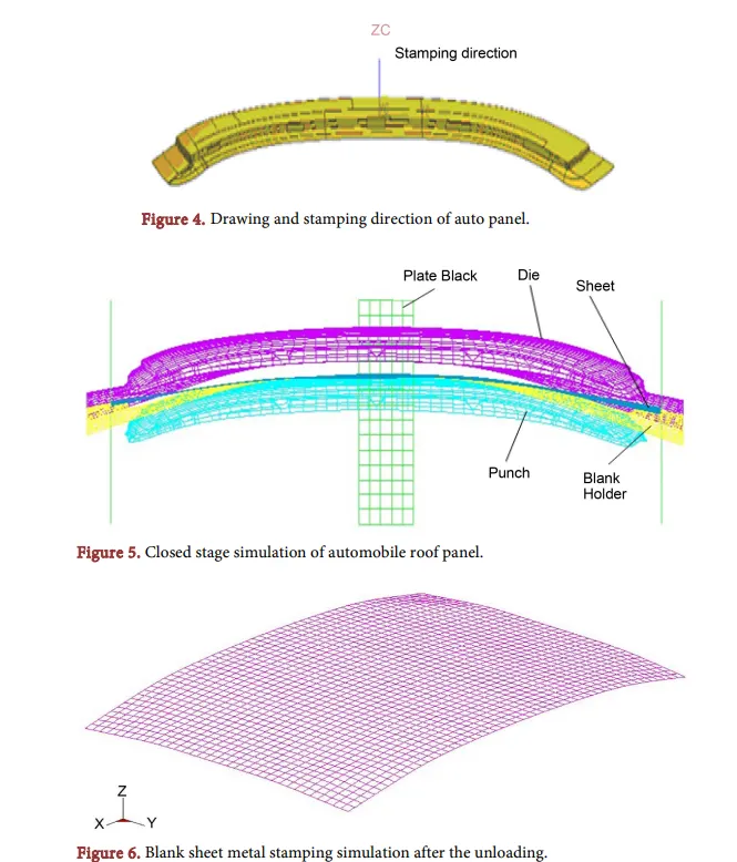
After taking stock of the grid model of gravity loading and further refinementtake the grid size 10 mm, the billet steel plate thickness is 0.7 mm and the calculation automatically by the program areas of intense deformation re-division ofthe minimum mesh size 2 mm. The sheet metal parameters are defined as follows, the sheet metal thickness 0.7 mm, Poisson’s ratio (V) 0.3, elastic modulus
(E) 207 GPa, tensile strength (TS) 3 MPa, yield strength (σ) 174 MPa,, mass density (ρ) 7.83 × 10⁹ kg/mm3 strain hardening coefficient (K) 518 MPa, thicknessanisotropy coefficient 1.91, 1.65 and 2.2 and the hardening coefficient (n) 0.242Pa.In the molding process stamping simulation of the blank sheet usually set inthree phases, such as simulation of the blank holder (closed stage), forming simulation stage and unloading springback simulation stage. In the closing stage,the blank holder must be added before the forming simulation stage, but no
blank holder force should be applied, and the drawing type is single action.Moreover, the upper and lower blank holder gap is set to (t) as a blank thicknesstogether and speed is 5000 mm/s.
5.3. Addendum
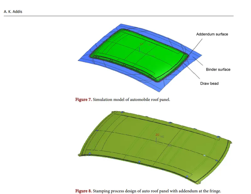
Addendum is a key element in the part of the stamping process design. Stampingdirection is determined by the direction of drawing to meet the requirements ofthe implementation process. However, the vast majority of auto body panelwhich requires stamping are determined by the shape, contour or depth of addendum designed draw bead. Advanced stamping process design is an important indicator whether the addendum parts directly affects the drawing processwhile the deformation parameters rough conditions applied. The size of deformation, the deformation distribution, surface quality, cracking, wrinkling andother problems are the indicator of design failures. Addendum should be designed to comply with the car body panel complementarily with the whole surfacepart, in a simplified structure and attractive enough.