Roof challenge
- Roof Design Assembly View
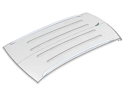
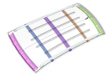
- Manufacturing Processes
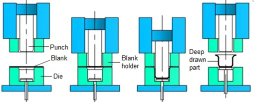
- Deep Drawing
- It changes a flat sheet metal blank into a cylindrical container with a flat or hemispherical base.
- The ratio of height (`p`) to diameter (`d_p`) of the product is greater or equal than 0.5.(`h/d_p >= 0.5`)
- It occurs under a combination of tensile and compressive conditions.
- The blank will be clamped between the Blank holder (binder) and the die first and then, the punch (stamp) stretches the sheet over the die and forms it in the die.
- To withdraw the stamp easily after the process, it requires some draft angles of emboss and lubricant.
- The optimum clearance (`C`) between die and punch is 10% more than sheet metal thickness (`t`), which is enough to avoid shear failure. `c = 1.1 xx t`
- The corners of die should be filleted to prevent shearing failure.
- The optimum blank holding force (`F_h`) is one third of drawing force (`F_d`). If it is bigger than optimum force, it makes shearing at die corners. If it is lower, it results in wrinkling defect at flange of product. `F_h = F_d/3`
- Pros
- Rapid operation cycle
- Low cost for large quantities
- Low maintenance
- No Seams
- Strength (material hardening during deformation increases the strength)
- Uniformity
- Waste material could be recycled or later use in other applications.
- Cons
- Not proper to small quantities
- High initial (installation) cost
- Significant experience and expertise, rendering deep drawing required
- Formability limitations
- Radial drawing stress and tangential compressive stress may result in wrinkling, fracturing, and cracking.
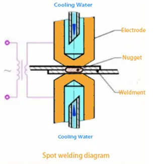
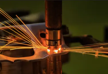
- Spot Welding (Resistance Spot Welding)
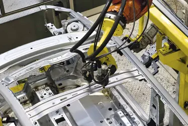
- It is most common joining process in high volume manufacturing lines, particularly in the construction of steel cars.
- It is used for joining overlapping sheet metals where high strength and durability are not required.
- It uses a heat obtained from resistance to electric current for welding two or more sheets of metal.
- Two copper alloy electrodes concentrate welding current into a small spot while clamping the sheets together at the same time.
- When the current is applied, the sheet metals melt and fuse together.
- While the electrodes still exert pressure on the sheets, the molten nugget solidifies to form the joint after the current is turned off.
- Typically, 0.5 to 3 mm (0.020 to 0.118 in) thickness sheets are used.
- Low carbon steel is the most suitable material due to its low thermal conductivity and high electrical resistance.
- Pros
- Short welding time (10 - 100ms) compared to TIG or MIG
- No slag
- Non-consumable electrode
- Good for light materials like Al (even though it requires higher welding current than low carbon steel)
- Versatility (Easy training & Less experience needed)
- Low cost
- Minimal material distortion
- Cons
- High initial cost
- More space required for installation
- Weak joint
- Bad surface finish
- Not ideal for thick sheets of metal
- Dangerous for welder due to high welding current, heat, and clamping pressure.
- Mastic joining process (Adhesive bonding)
- It is a permanent joint used in sheet metal parts.
- The adhesive is place between the part surfaces, and joining pressure is applied.
- When selecting the adhesive, there are factors to be considered like part surface geometry, material, bonding strength requirement, and moisture content in working environment.
- Cyanoacrylate, acrylic-based, epoxy-based, silicon-based adhesives are used for joining sheet metals.
- There are two types of adhesives, double-sided tapes, and liquid adhesives.
- Pros
- Do not make distortion, discoloration, or weld worms
- Invisible in the assembly
- No holes
- Stress distribution evenly over a broad area
- Resist flex and vibration stresses
- Can join complicated surfaces
- Can bond heat-sensitive materials
- Small weight increase
- Cons
- Assembly time increase due to adhesive curing process
- Surface preparation required which adds time and material costs
- Hard or impossible to disassemble the parts.
- Deep Drawing
- Roof Design Parameters
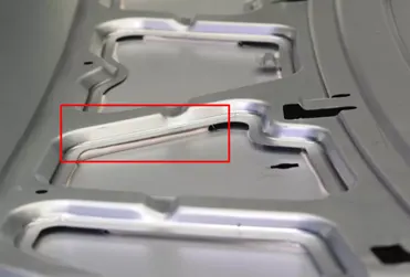
- The angle bigger than 7-degree is applied as a deep drawing angle for every embossing.
- For the spot welding, zero clearance is applied between two sheet metals.
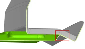
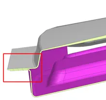
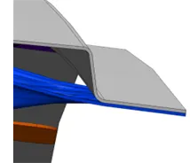
- Every roof rail has 5 mm gap from roof panel for mastics.
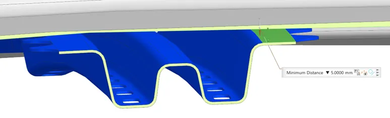
- Mastic points are determined as below. When mastic seal is applied, its near location is reinforced.
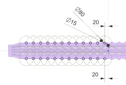
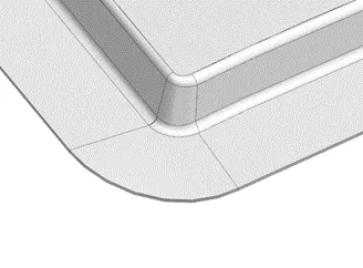
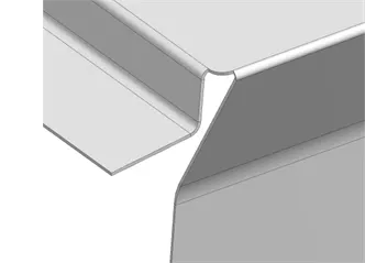
- The front corner of roof flange is well connected, and the rear flange corner has proper design to manufacture.
- Curvature Study
- Before sending the design to the CAE team, curvature study for the roof rails can be done to determine whether the design of roof reinforcements is proper or not. Here, two different curvature study, heat distortion and snow load prediction, will be done to validate the design.
- Bow-Roof Prediction
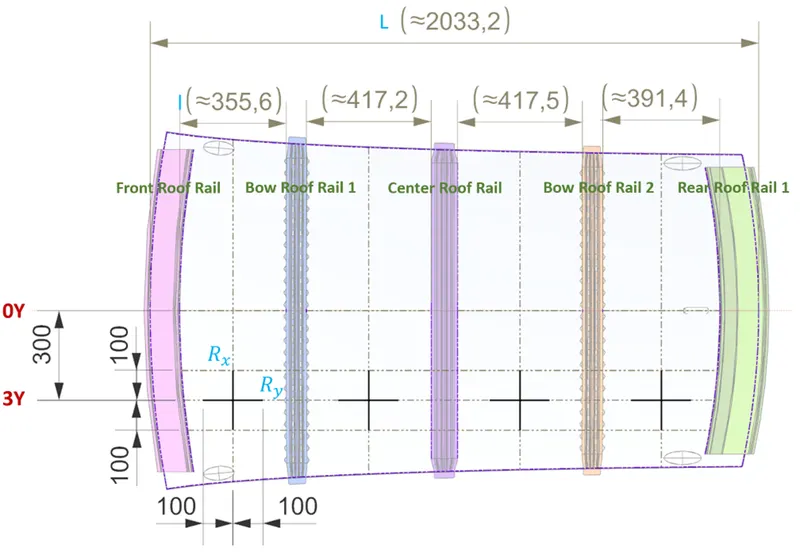
`W = [1.73 xx 10^(-3) xx L]+[1.85 xx 10^(-8) xx R^2//t] + [1.10 xx 10^(-3) xx l]-2.68`
L = Roof Length in X-Direction[mm] (Roof dimension in 0-Y)
R = Roof curvature, where, R = 2(Rx*Ry)/(Rx+Ry)
Rx = X curvature
Ry = Y curvature
t = Roof plate thickness [mm]
l = Bow Roof Span [mm]
* Judgment Condition
W < 2.7
-
It passed heat distortion criteria curvature study.

-
- Snow Load Prediction`Q_r = [I_y xx t^2]//[\alpha xx s xx [(R_x+R_y)//2]^2 xx 10^(-8)]`
α = My x Lx2 x 10-12 , My = Y(Ly-Y)
t = Roof plate thickness [mm]
Ly = Distance between the front and rear roof Rails on the Vehicle along with 0Y[mm]
Length of Roof panel with the center point between Roof rail Front /Rear as the
front and rear reference point.
Lx = Distance between the Left and Right end of the roof on the Roof BOW [mm]
The width of the roof panel is exposed on the surface.
Y = Distance front Front Roof Rail to Roof BOW[mm]
s = Distance for which Roof BOW bears divided load [mm]
s = L1/2 + L2/2
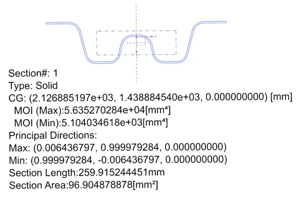
Iy = Geometrical moment of inertia of Roof BOW (Y cross-section )[mm4]
Rx = Lateral direction curvature radius of roof panel Y cross-section on Roof BOW [mm]
Roof panel curvature Radius of the Length Lx in Front view
Ry = Longitudinal Direction curvature radius of the Roof panel X cross-section on Roof BOW
[mm] Roof panel X curvature radius of length s in Side view
*Judgment condition
`Q_r >= 3.1`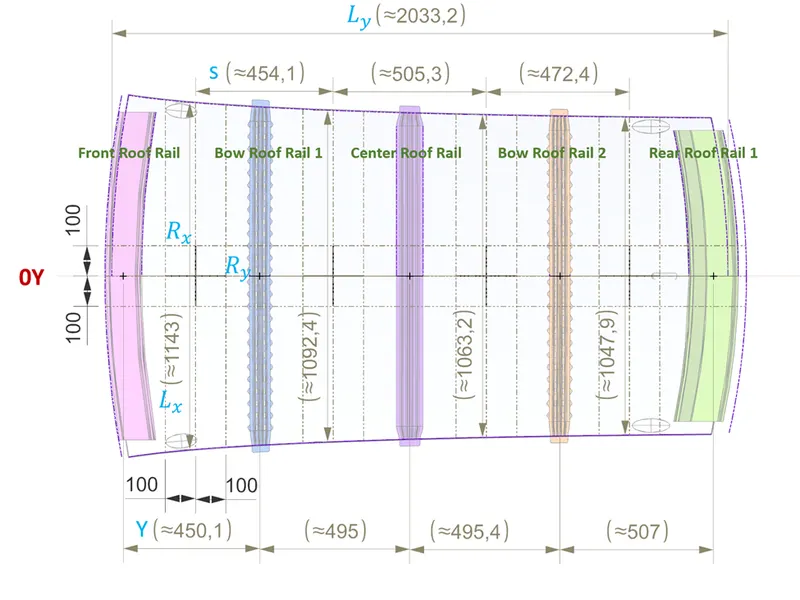
- Moment of Inertia of Bow Roof Rails
- Bow Roof Rail 1
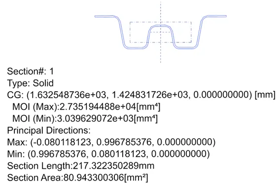
- Center Roof Rail
- Bow Roof Rail 2
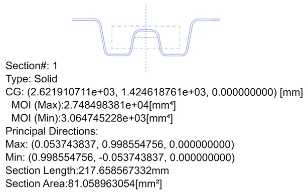
- Bow Roof Rail 1
- It passed snow load criteria curvature study.

- Moment of Inertia of Bow Roof Rails
- Before sending the design to the CAE team, curvature study for the roof rails can be done to determine whether the design of roof reinforcements is proper or not. Here, two different curvature study, heat distortion and snow load prediction, will be done to validate the design.
- Draft Analysis
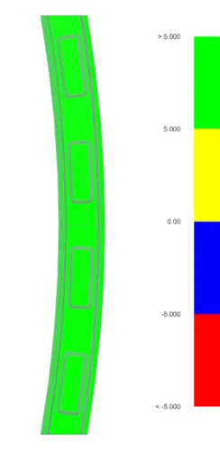
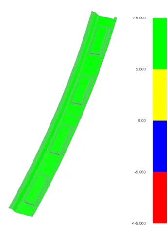
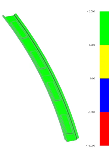
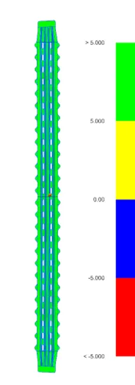
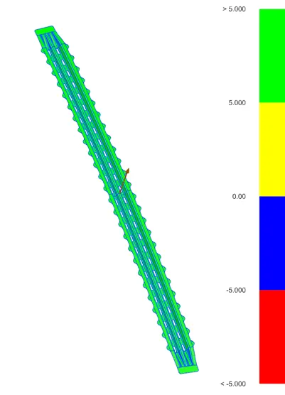
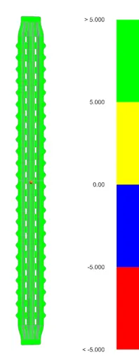
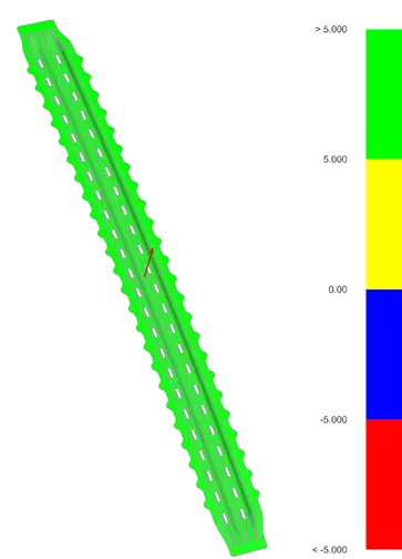
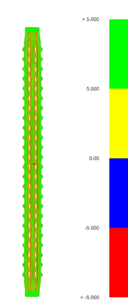
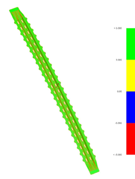
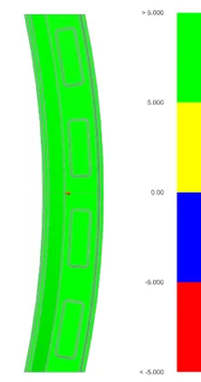
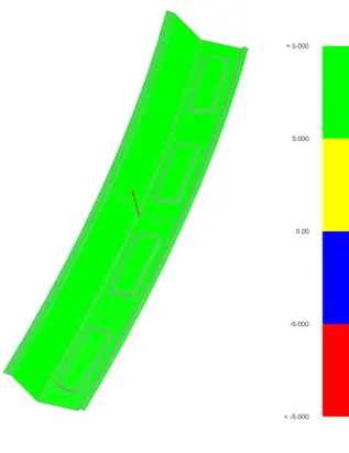
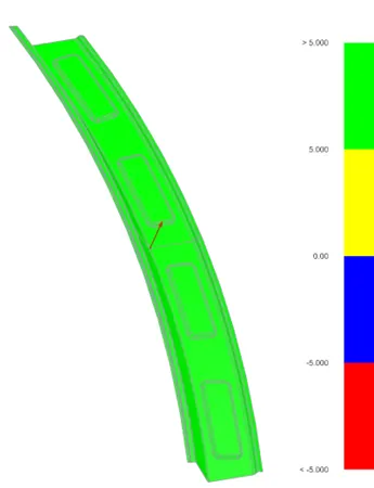
- Draft analysis is done to check whether the part can be manufactured by deep drawing process. To withdraw the stamp from the part easily, 5-degree angle is applied as a minimum criterion for draft analysis. When all faces of the component is bigger than 5-degree draft angle, it is able to manufacture.
- Roof Panel
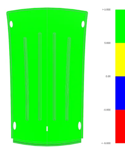
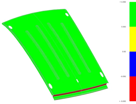
- Except rear roof, all other surfaces meet the criteria. The rear roof can be made by simply bending the sheet metal so, the design is manufacturable.
- Front Roof Rail
- Bow Roof Rail 1
- Center Roof Rail
- Bow Roof Rail 2
- Rear Roof Rail
- Conclusion (Possible remedies when the criterion is not full-filling)
This roof design can be manufactured with deep drawing, spot welding and mastic joining process. Moreover, it passes all curvature studies which means it has enough strength against the roof crash.
Even though this design passed the curvature study, let's assume there is a design failed to pass the study. In that case, several reinforcing strategies can be applied. First, roof rails can be strengthened by increasing the moment of inertia. It can be achieved by increasing width or emboss depth. Second, the position of bow roof rail can be adjusted to get the better curvature. If the radius curvature decreases the Qr value of snow load criterion increases. Lastly, embosses can be added to the roof panel to distribute the crash force evenly over the surface.