Roof challenge
Introduction
The BIW component of an automobile that is located above the passenger compartment and shields the occupants from the sun, wind, rain, and other elements is known as a car roof or car top.
Design
Front Roof Rail: Body side outer scrap is used to make the front roof rail. The front roof rail serves as reinforcement for that area of the roof. To achieve the driver visibility requirements, the offset distance between the front roof rail surface and the roof top surface should be kept below certain value. In order to preserve the head clearance criteria—80mm minimum—the width of the front roof rail, should be less than designated distance. The back end of the front roof rail is attached to the roof with mastic sealant since it is not covered with head liner, which would otherwise give a poor appearance.
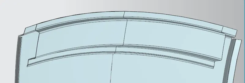
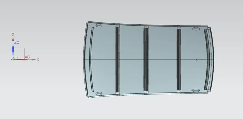
Bow Roof: These are the reinforcements used to improve the roof's ability to support more weight. Depending on length of the roof, there may be one, two, or more bow roof rails. Bow roof rails are welded to the side flanges of the roof to secure them to the surface. Using mastic sealants, the roof and the bow roof rails' center section are joined. The roofs get stronger due to the mastics, which also has an 80mm radius of influence. Through a study of the roof's curvature and analysis, the bow roof rails are placed.

Reinforcement Center: To strengthen and stabilize the roof, a center roof rail will be positioned. Here, mastic sealant is used to adhere the central roof rail to the roof.

Rear Roof Rail: Body side outer scrap is used to make the rear roof rail. The rear roof rail serves as a reinforcement for the back of the roof. The rear roof rail should meet the same minimum head clearance and visibility requirements as the front roof rail. The front end of the rear roof rail is attached to the roof using mastic sealant since it is not covered with head liner, which would otherwise give it a horrible appearance. The rear end of the rear roof rail is welded to the roof.
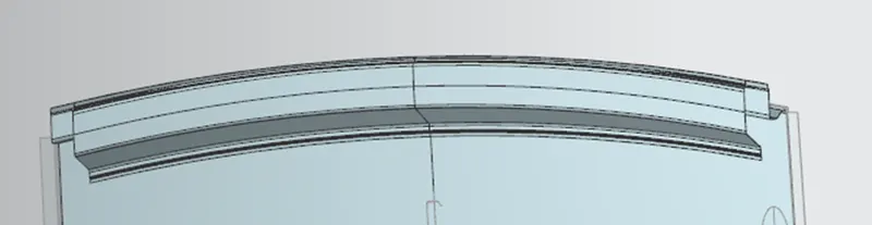
Ditch Area: To meet the visibility requirements, the ditch region of the roof has a tool opening angle of 3 degrees, and the flange is given enough space above it to accommodate windshield glass and rubber sealants. Below the ditch region, on its flange, the front roof rail is welded.
Roof Assembly:
All the parts are designed according to given dimensions for the roof rails. The side flanges of the roof must have draft angle of 7degrees or more and these 2 flanges are welded with the bow roof rails below it. The rear portion of the roof is associated with the back door and has rear roof rail welded below it. The thickness of my roof design is 0.75mm.
Bow–Roof Prediction Formula
W = [1.73 x 10^(-3) x L] + [1.85 x 10^(-8) x (R^2)/t] + [ 1.10x10^(-3) x l] - 2.68
where,
L = Roof Length in X-Direction[mm] (Roof dimension in 0-Y)
R = Roof curvature
R = 2(Rx*Ry)/(Rx+Ry)
Rx = X curvature
Ry = Y curvature
t = Roof plate thickness [mm]
l = Bow Roof Span [mm]
Judgment Condition: OK< 2.7
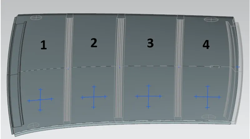
Calculations -
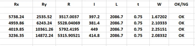
Hence, the bow roof conditions are satisfied.
Snow Load Prediction Formula
Qr = [Iy x t2] / [α x s x [(Rx + Ry)/2]2 x 10-8]
where,
α = My x Lx2 x 10-12, My = Y(Ly-Y)
t = Roof plate thickness [mm]
Ly = Distance between the front and rear roof Rails on the Vehicle along with 0Y[mm]
Length of Roof panel with the center point between Roof rail Front /Rear as the front and rear reference point.
Lx = Distance between the Left and Right end of the roof on the Roof BOW [mm]
The width of the roof panel is exposed on the surface.
Y = Distance front Front Roof Rail to Roof BOW [mm]
s = Distance for which Roof BOW bears divided load [mm]
s = L1/2 + L2/2
Iy = Geometrical moment of inertia of Roof BOW (Y cross-section) [mm4]
Rx = Lateral direction curvature radius of roof panel Y cross-section on Roof BOW [mm]
Roof panel curvature Radius of the Length Lx in Front view
Ry = Longitudinal Direction curvature radius of the Roof panel X cross-section on Roof BOW [mm]
Roof panel X curvature radius of lengths in side view
Judgment condition: Qr ≥ 3.1 & 250 ≤ s ≤ 380
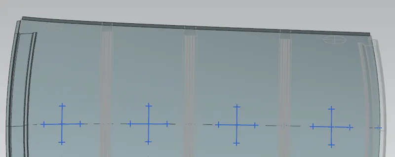
Bow Roof 1:
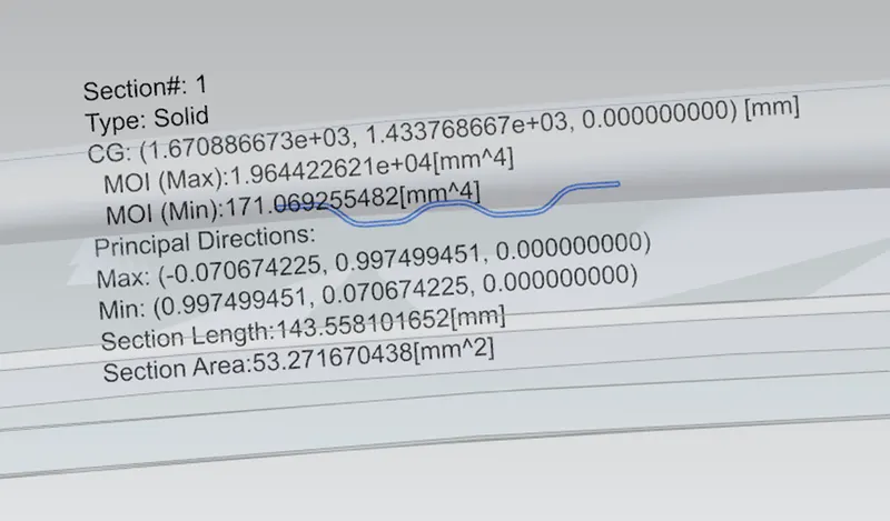
Center Roof Rail:
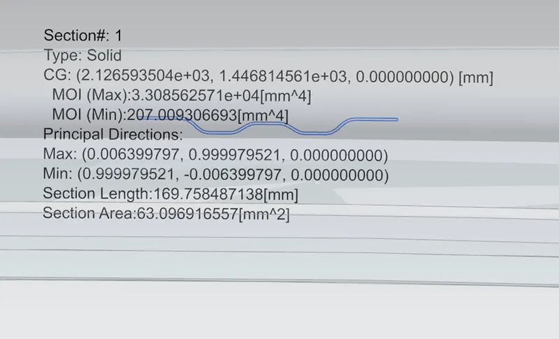
Bow Roof 2:
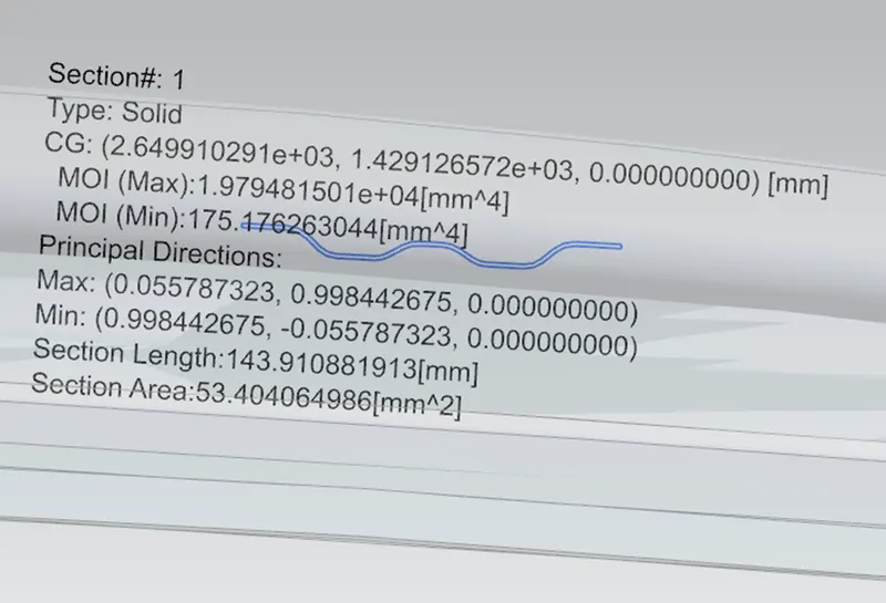
Calculations -

As these values does not satisfy snow load conditions, so we can create emboss to strengthen the roof.
Draft Analysis
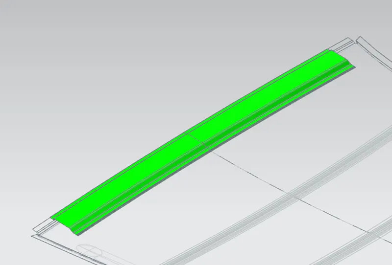
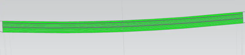
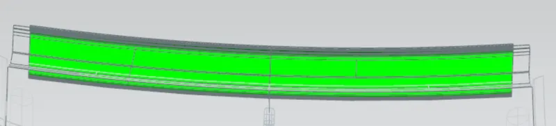
The draft analysis is done to check the positive or negative draft of the part for its manufacturability. It is done with the help of draft analysis tool in NX Cad and keeping the draft angle as 3 degrees. The green color means the draft angle is greater than 3 degrees.
Conclusion
For improved support and strength, we were able to design the roof. By computing the heat distortion requirements and the snow load criteria, we were able to construct it in a way that complies with the standard regulations.