Roof challenge
Detail report on roof design
AIM
To develop the essential flanges and reinforcements inside the roof to increase the strength of the roof and check the draft by performing draft analysis, calculating section inertia, heat distortion and snow load on the roof.
ROOF
An automobile roof or car top is the portion of an automobile that sits above the passenger compartment, protecting the vehicle occupants from sun, wind, rain, and other external elements.
INTRODUCTION
Automotive roof plays an important role in aerodynamics and internal strength of vehicle. The roof’s BIW influences the aftermath effects of crush load, snow load and heat distortion criteria. The roof has internal structures like front roof rail, rear roof rail, bow roof 1, bow roof 2, rear roof rail and reinforcement roof rail. In this project these structures were designed accordingly. Their position were also justified with the required criteria. Generally roofs are given a curvature along Xc and Yc. But some places of roof have flatness compared to other section, mostly while approaching the trailing edge of roof the roof becomes flat relatively. Sometimes this flatness is intentionally given to reduce the creation of a wake region while moving faster. The roof is like building a house. The house needs pillars, similarly the roof needs the above quoted internal structure to ensure safety and performance. The roof has to perform good in roll over test. The outer panel of roof is considered as class A surface, so there cannot be any spot welds or any visible fastening. Mastics plays major role in engaging the roof panel and the internal BIW parts.
SOFTWARE USED : SIEMENS NX12
AUTOMOTIVE ROOF
They act as a passenger cabin and protects from sun, rain, wind, dust, etc. Roof variations
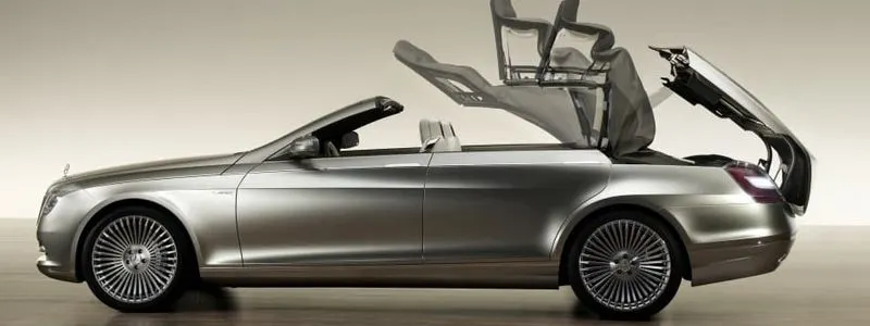
1.Convertible roof
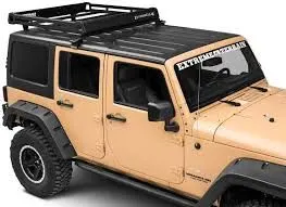
2.HARDTOP
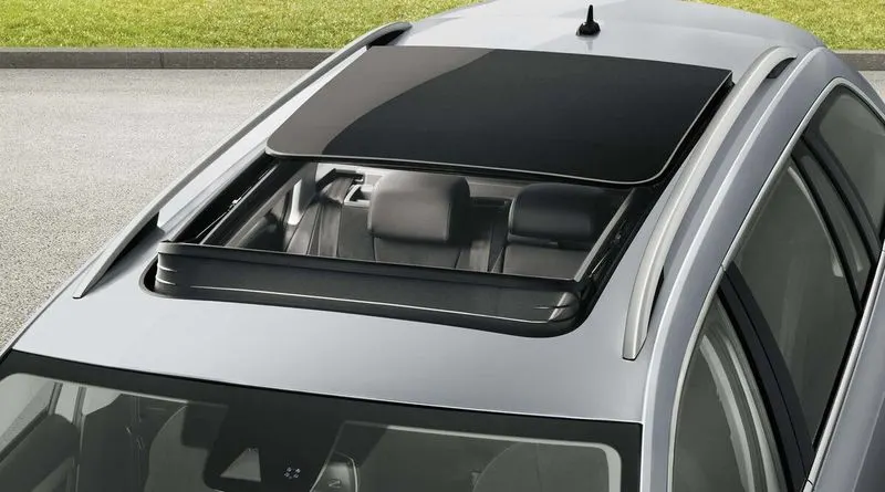
3.SUNROOFS
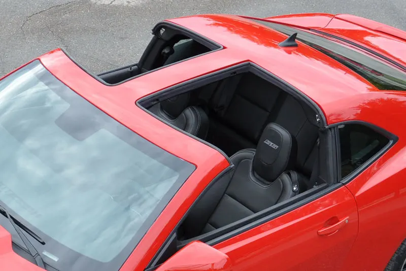
- T TOP
ROOF STRUCTURE
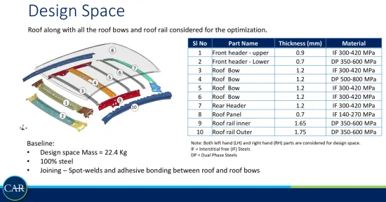
Apart from aerodynamic shape of roof it has to withstand the induced drag force on surfaces. To make the roof more structurally rigid and to improve its local strength the BIW parts designed.
The internal components of roof are
- Front roof rail
- Rear roof rail
- Reinforcement roof rail
- Bow roofs
These structures also facilitates for cabin amenities like lighting and some other electrical electronic instruments
Front Roof Rail Master section Reference Image
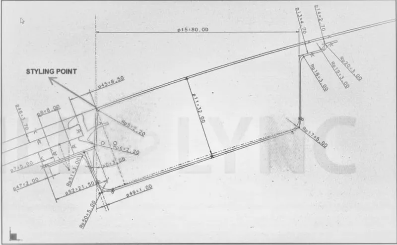
This master section is used to design the front part of the roof and has been designed and fitted into the outer roof this inner roof improves the strength of the roof.
FRONT ROOF RAIL
the master sketch has all the geometrical details for the front panel some amount of space is provided for the windshield and the rubber lining to get perfect fit.
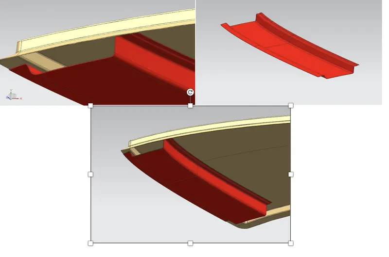
BOW ROOF 1
Bow roof 1 is mounted next to the front roof bow roof improves the strength of the panel.
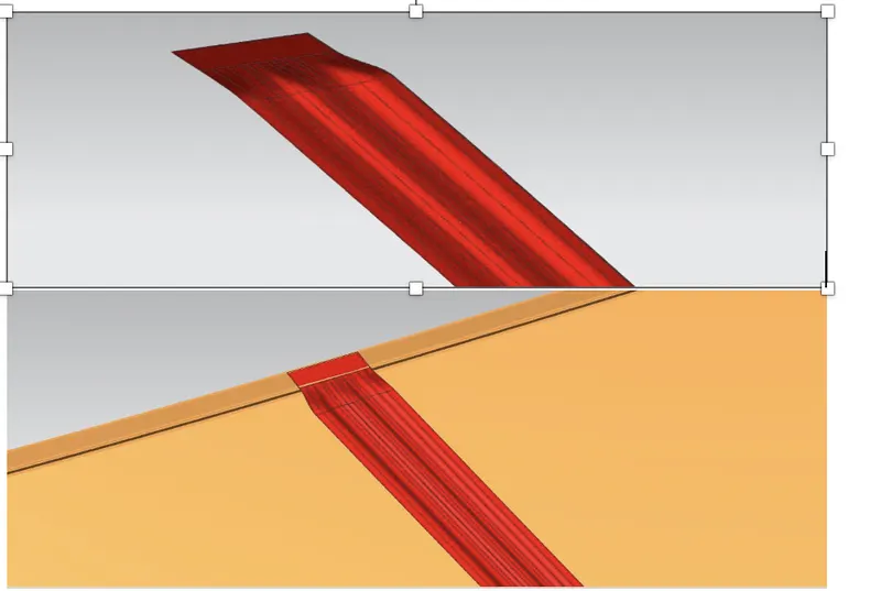
CENTER ROOF RAIL
Center roof rail is present in between two bow roof to improve the strength of the overall outer panel
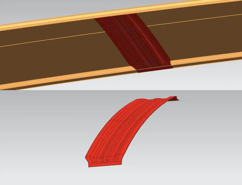
BOW ROOF 2
Bow roof 2 is mounted next to the front roof bow roof improves the strength of the panel.
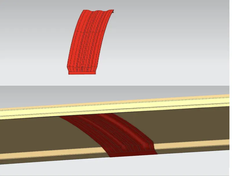
REAR ROOF RAIL
one of the important parts is located at the end of the outer roof as per the master section this rear rail is designed.
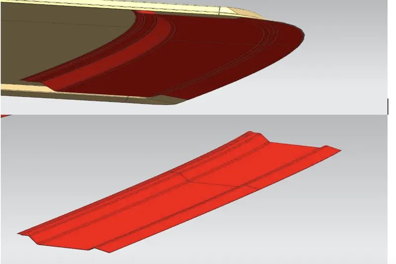
OVERALL VIEW OF THIS PANEL
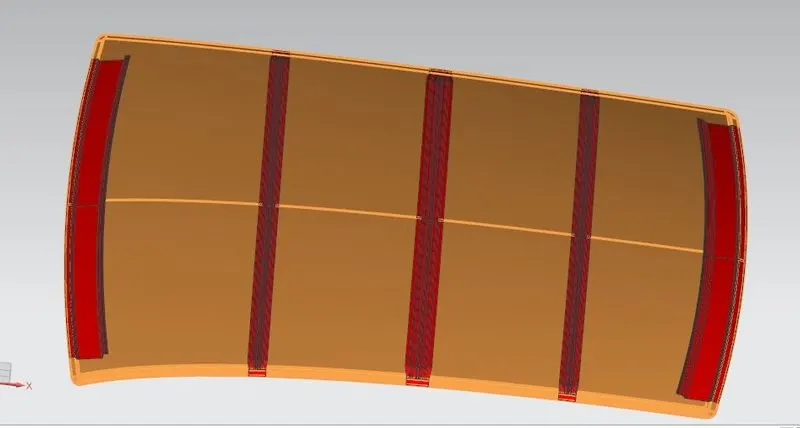
OVERALL VIEW WITHOUT OUTER PANEL
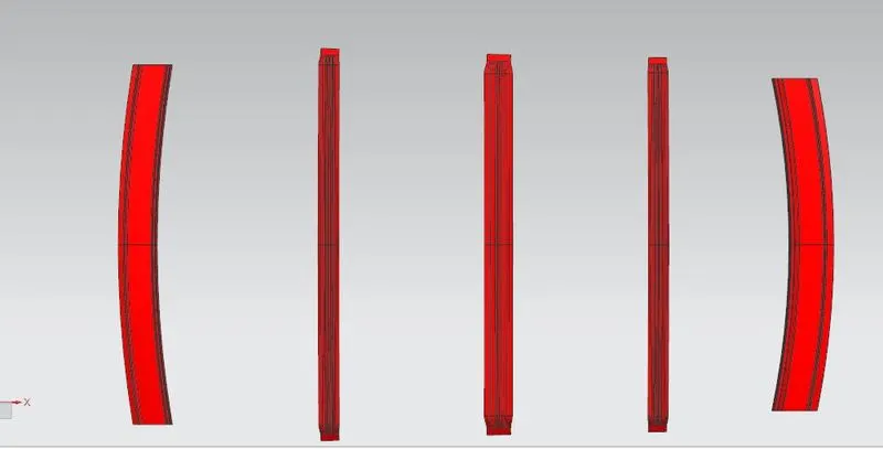
HEAT DISTORTION CRITERIA:
Heat distortion temperature is the temperature at which metal softens and deforms under a specified load. While designing roof, this criteria is taken into consideration. We create bow roofs when the roof is long and flat to increase its strength. The position of the bow roofs is to be justified and this justification is done by curvature study:
Bow - Roof prediction Formula
Bow–Roof Prediction Formula
W = [1.73 x 10^(-3) x L] + [1.85 x 10^(-8) x (R^2)/t] + [ 1.10x10^(-3) x l] - 2.68
Where,
L = Roof Length in X-Direction[mm](Roof dimension in 0-Y)
R = Roof curvature
R = 2(Rx*Ry)/(Rx+Ry)
Rx = X curvature
Ry = Y curvature
t = Roof plate thickness [mm]
l = Bow Roof Span [mm]
Judgment Condition
OK< 2.7
TO MEASURE L
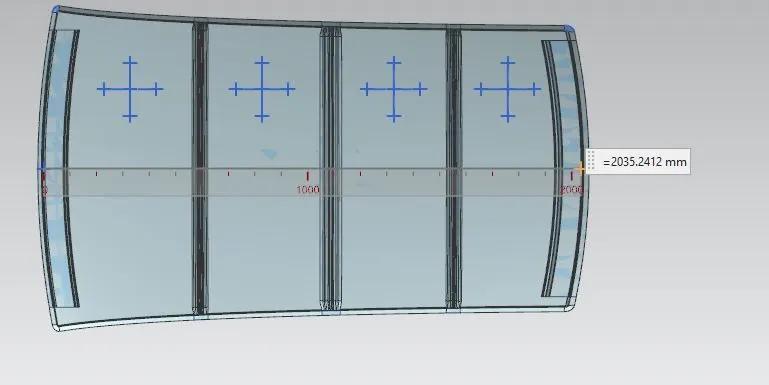
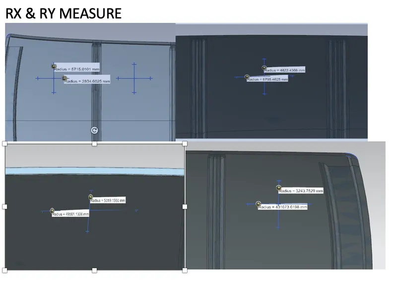
HEAT DISTORTION CONDUCTION

All the values are not satisfied for heat distortion conduction
Snow Load Prediction Formula
Qr = [Iy x t2] / [α x s x [(Rx + Ry)/2]2 x 10-8]
Note: The Qr value given over here is correct. There was a typo error in the formula given in the video.
Where,
α = My x Lx2 x 10-12 , My = Y(Ly-Y)
t = Roof plate thickness [mm]
Ly = Distance between the front and rear roof Rails on the Vehicle along with 0Y[mm]
Length of Roof panel with the center point between Roof rail Front /Rear as the front and rear reference point.
Lx = Distance between the Left and Right end of the roof on the Roof BOW [mm]
The width of the roof panel is exposed on the surface.
Y = Distance front Front Roof Rail to Roof BOW[mm]
s = Distance for which Roof BOW bears divided load [mm]
s = L1/2 + L2/2
Iy = Geometrical moment of inertia of Roof BOW (Y cross-section )[mm4]
Rx = Lateral direction curvature radius of roof panel Y cross-section on Roof BOW [mm]
Roof panel curvature Radius of the Length Lx in Front view
Ry = Longitudinal Direction curvature radius of the Roof panel X cross-section on Roof BOW [mm]
Roof panel X curvature radius of length s in Side view
Judgment condition
Qr ≥ 3.1
250 ≤ s ≤ 380
RX & RY VALUE FOR SNOW LOAD CONDITION
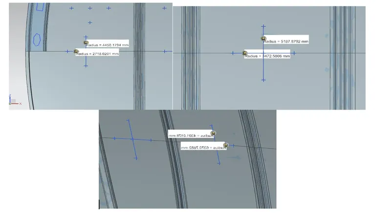

So, according to the Judgement condition = Qr ≥ 3.1
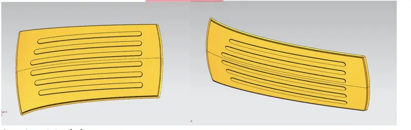
And, Here one result of Qr is not fulfilling the demand. So, there are some solutions, that the model can pass over to the styling team to change the curvature to improve the strength, Bow Roof rails position can be changed to the weaker side of roof or Embosses could be created on the outer panel to improve the strength.
To improve the strength, the embosses are created.
Section Modulus:
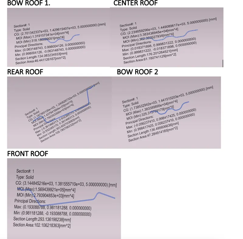
Section modulus is a geometric property for a given cross-section used in the design of beams. Other geometric properties used in the design include an area for tension, radius of gyration for compression, and moment of inertia for stiffness. The Section modulus is defined as
S=Iy
Where
S = Section Modulus
I = Moment of Inertia
y = Distance from the neutral axis to any given part.
Front Roof rail
The intersection was created and then Section Inertia command was used to obtain MOI
Draft Analysis
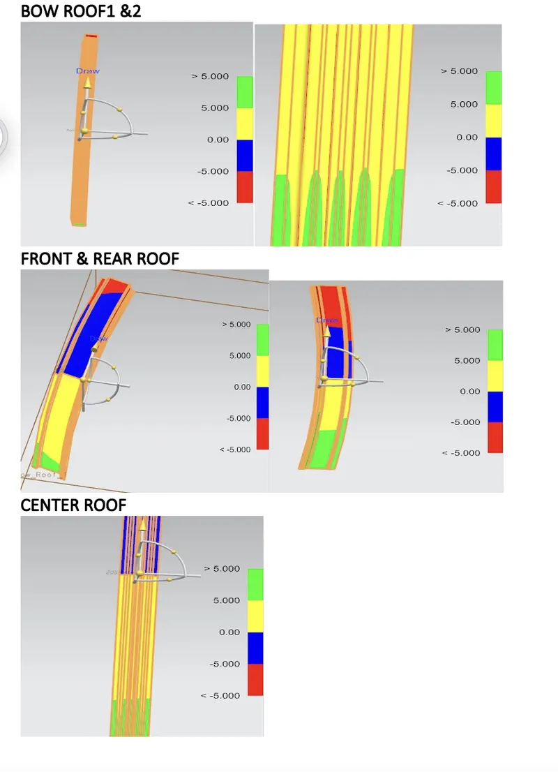
Draft analysis was performed with 7 Degrees Value(generally given in sheet metal)
Conclusion
The Roof was created in Siemens NX Student Version with all the required parameters and different Calculations were done for safety concerns.