Roof challenge
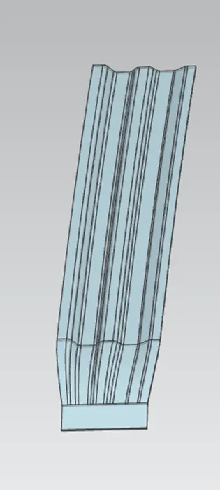
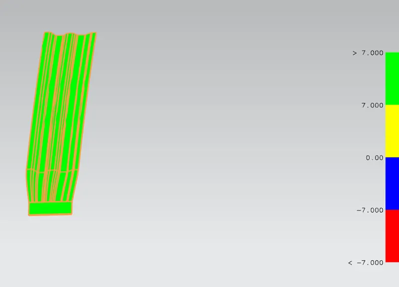
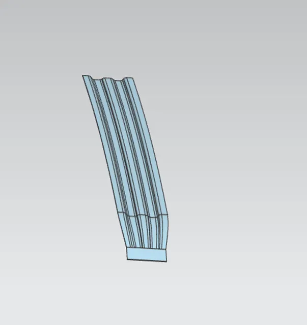
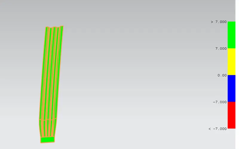
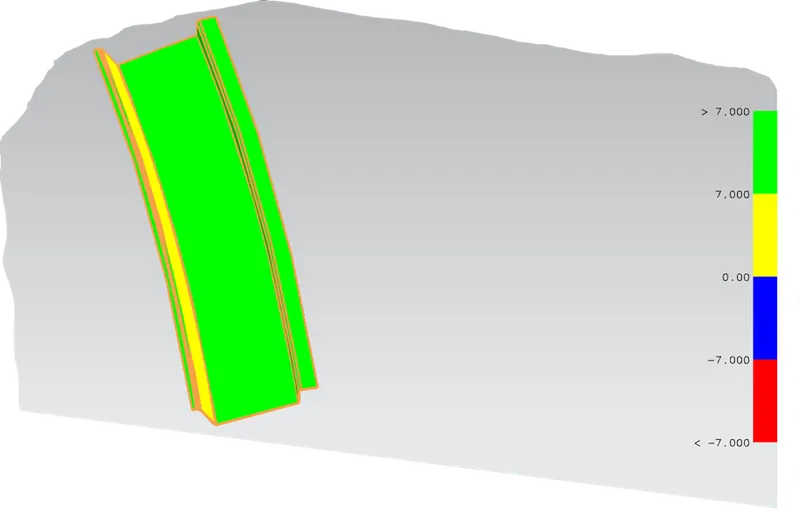
Bow roof rail is used for adding stiffness to the roof in the localized area and it is attached to the roof with the help of mastic sealant. The bow roof rail is a technique that will increase the stiffness of the surface without affecting the aesthetic view of the roof. In the present work, three bow roofs were used at different locations. The draft analysis performed for three bow roofs is given in the below figures. From the draft analysis, it is understood that the surface of the three-bow roof appears green which indicates the draft angle is greater than seven and accepted for production.
Front bow roof rail 1
Middle roof rail
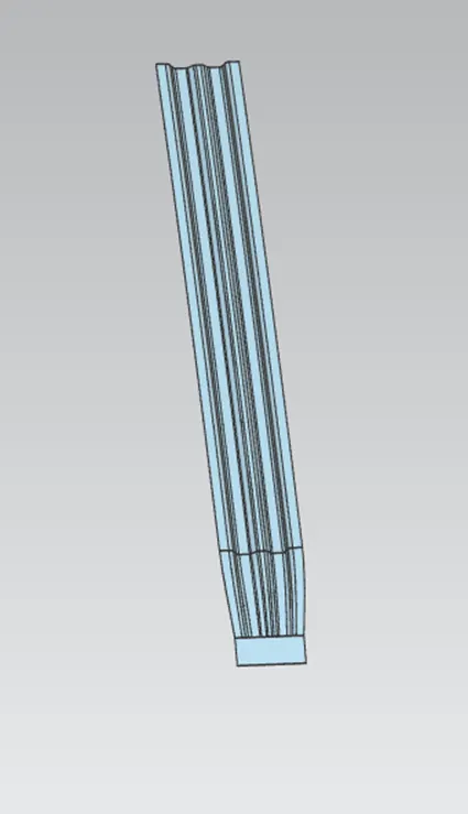
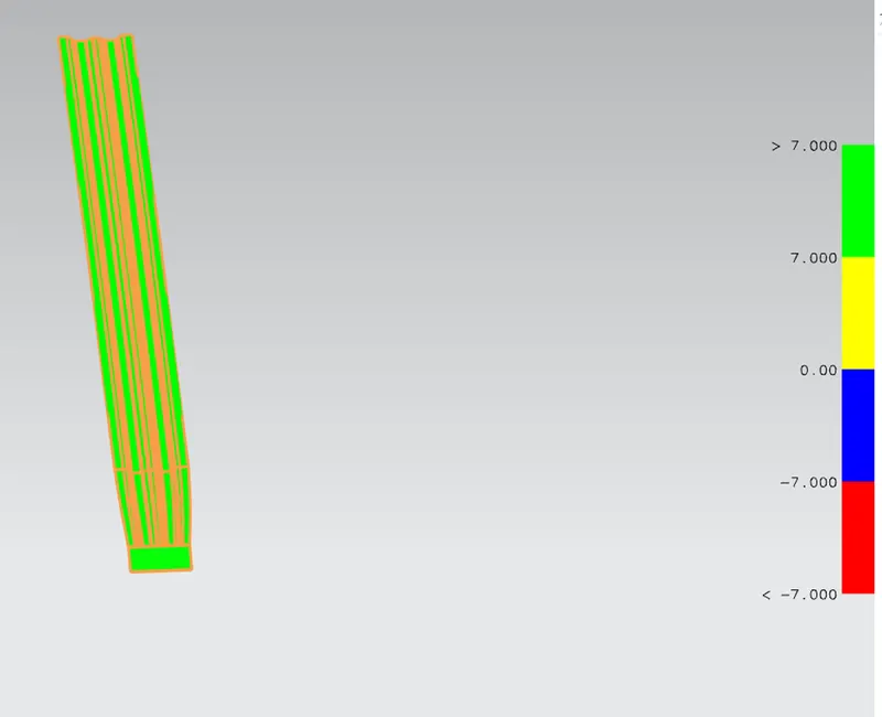
Last rail roof
Roof
The roof structure was done with the draft analysis and it is shown in Figure. From the figure, it is seen that the given surface has no undercut problems and it can go for production.
Front rail
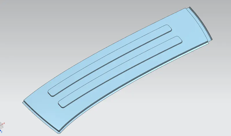
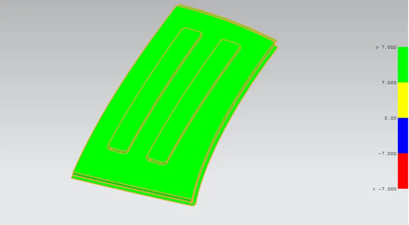
The front rail is used to connect the windshield joins. The front rail is designed by considering the visibility criteria and headroom clearance of the passenger. The front rail is joined on one side with spot welding and the other side with mastic sealant to enhance the stiffness of the surface. From the draft analysis, it is seen some portion is looking yellow which indicates that the draft angle is less than seven degrees but still it can go for production. If the color appeared to be blue and red is not fit for production and yellow is acceptable.
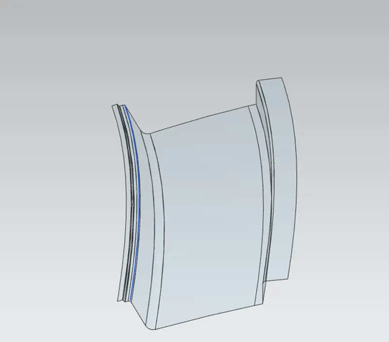
Rear roof rail
The rear roof is used to join the back door and roof and the back door input is considered for designing the rear roof rail their draft analysis showed that draft angles are greater than seven degrees and there is no undercut.
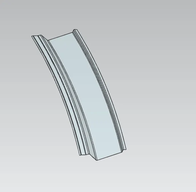
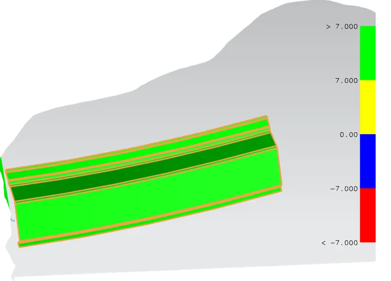
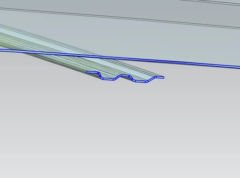
A gap is given between the roof and bow for the attachment of the joints
Heat distortion curvature study:
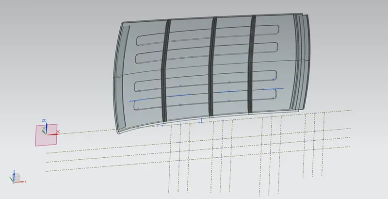
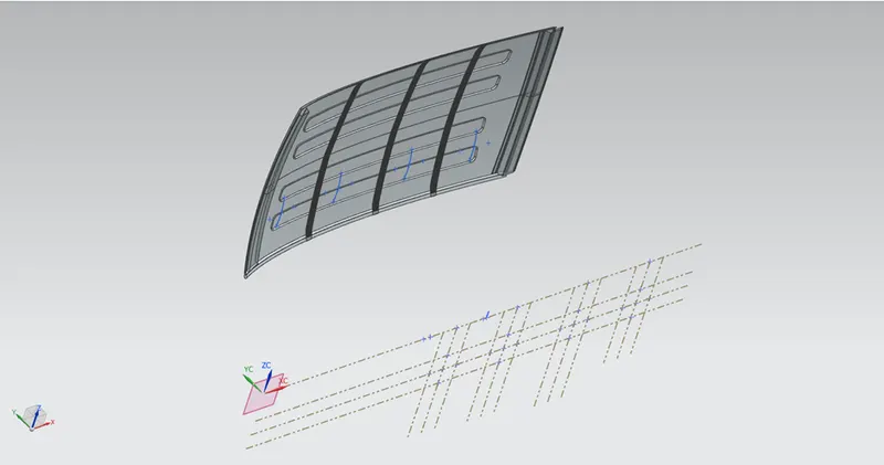
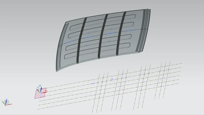
This study helps to determine at what location the deformation will be happening on the roof and where the place bow for strengthening the roof surface. These were determined using the correlation by finding the curvature area of the surface in the X and Y directions as shown in Figure. In order to pass the heat distortion test ‘W’ value should be less than 2.7. For the calculation, the roof was divided into four sections and various performance parameters were calculated and measured the calculated value of ‘W’ is shown in Table. From the table, it is understood that the heat distortion values are satisfied for all four cases.
Ry CURVATURE
Rx CURVATURE
Calculation of heat distortion curvature study
|
Section |
Rx |
Ry |
R |
I |
L |
t |
R^2/2 |
w |
Result |
|
Front roof to Bow1 |
596 |
4070 |
1039.743 |
393 |
1933 |
0.75 |
540532.6 |
1.087686 |
SATISFIED |
|
Bow1 to Center Bow |
585 |
3167 |
987.5773 |
363 |
1933 |
0.75 |
487654.5 |
1.054778 |
SATISFIED |
|
Center Bow to Bow 3 |
578 |
10469 |
1095.516 |
448 |
1933 |
0.75 |
600077.5 |
1.146174 |
SATISFIED |
|
Bow 3 to Rear roof |
571 |
6939 |
1055.172 |
409 |
1933 |
0.75 |
556693.5 |
1.104644 |
SATISFIED |
Snow load criteria
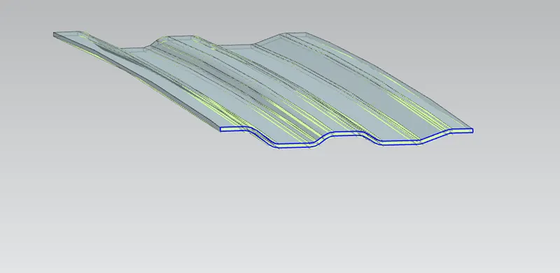
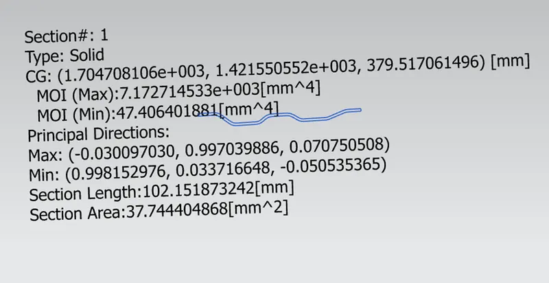
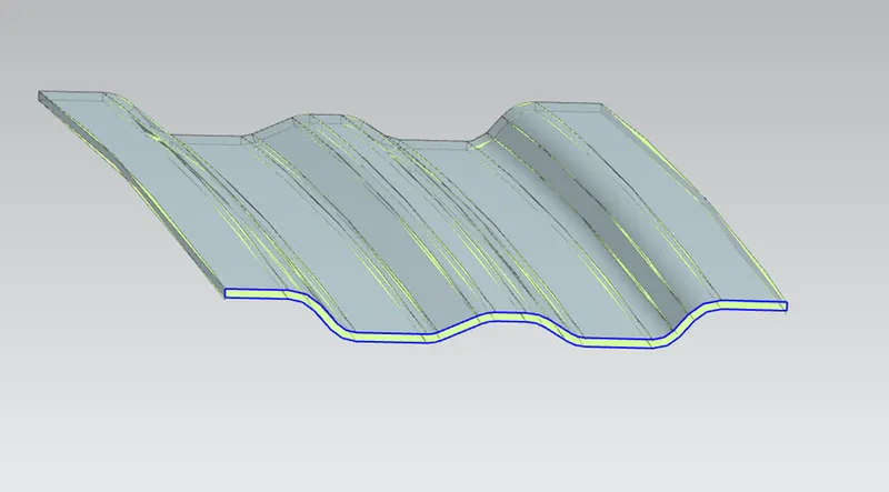
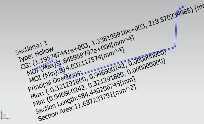
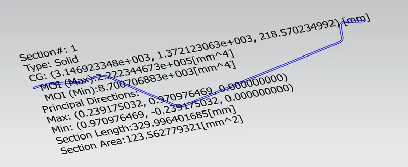
Initially, snow load was predicted by calculating various parameters as shown in Figure and further the changes were made in the design to satisfy the criteria. From the table, it is understood the given bow rail roof structure of thickness of 0.75 mm was not meeting the snow load criteria to overcome this a cross-section was taken for each bow roof rain, and an offset operation was performed. By increasing 1.7 mm the bow roof is meeting the criteria for the same of Qr > 3.1.
Rx curvature
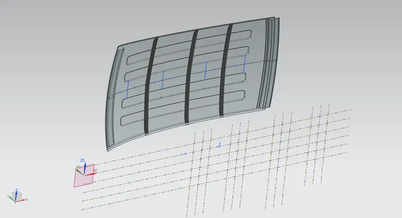
Ry curvature
MOMENT OF INERTIA (Iy)
Bow 1
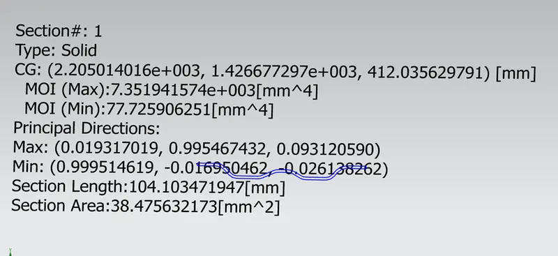
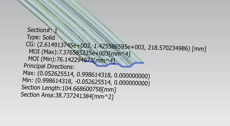

Modified
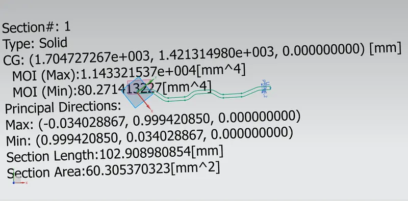
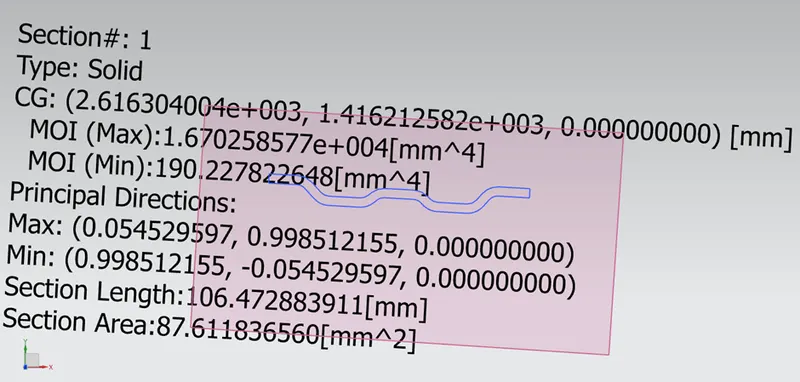
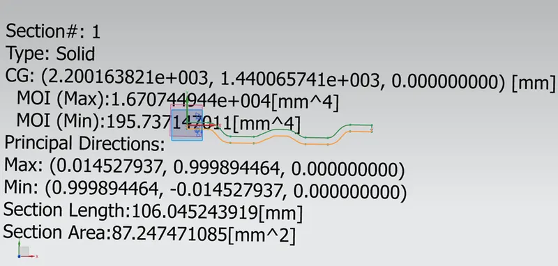

Sectional Inertial analysis of front and rear end rail roof
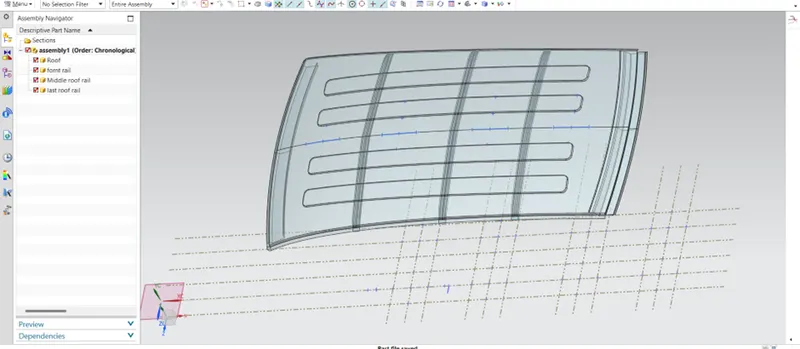
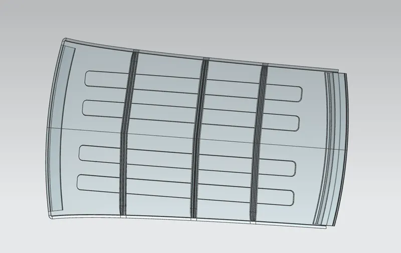
Car roof 3D model
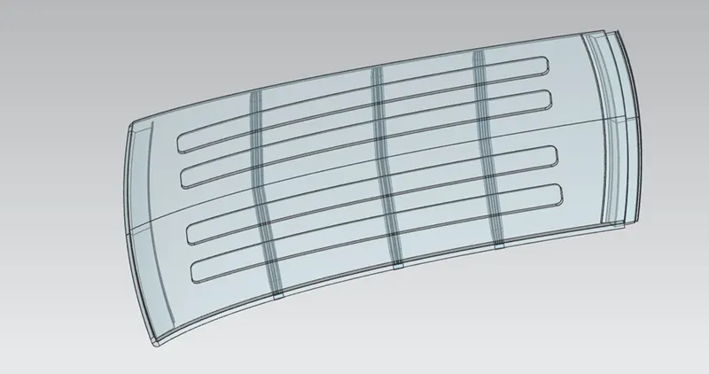
This complete 3D model of the roof structure
Conclusions
The roof 3D model was developed by considering the industrial standards. In this study, heat distortion and snow load were carried out and calculations were presented in the study. Based on the various parameters the design modification was made and implemented in the software for further study. These design criteria help to understand the techniques adapted for designing car roofs.