Roof challenge
INTRODUCTION
In this project, we study the design and making of roof and its components, with the help of the skin data and the master section provided. We are to make the roof assembly, comprising of the roof outer panel, roof front, centre and rear rails and also the bow roofs to provide roof reinforcement. It has to be made in such a wat that it doesn’t hamper visibility at any angle, is aerodynamic enough and also gives enough head room for passengers inside the cabin.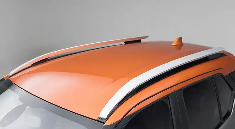
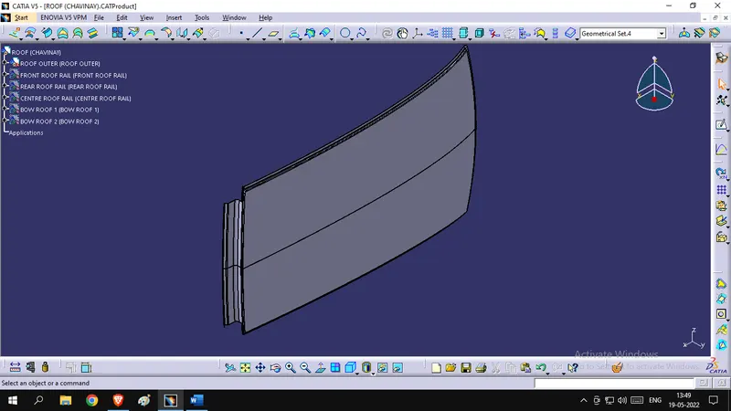
Roof Outer Panel
This is the main roof which is visible aesthetic part and is painted too, to withstand the weather condition and also look good, grooves and ridges are made to allow air flow and make the roof strong.
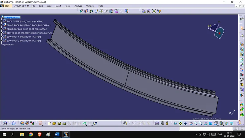
Front Rail
This connects the front part of the roof, to the front part of the rest of the vehicle body, that are the A-pillars, at both right and left of the vehicle. It also acts as a reinforcement for the windshield of the vehicle.
Rear Rail
This does one extra thing apart from doing all the mentioned jobs of the front rail, that is to provide space and help to the back door of the vehicle. The rear windshield is sometimes on the door or depends on the type of vehicle the roof is made for.
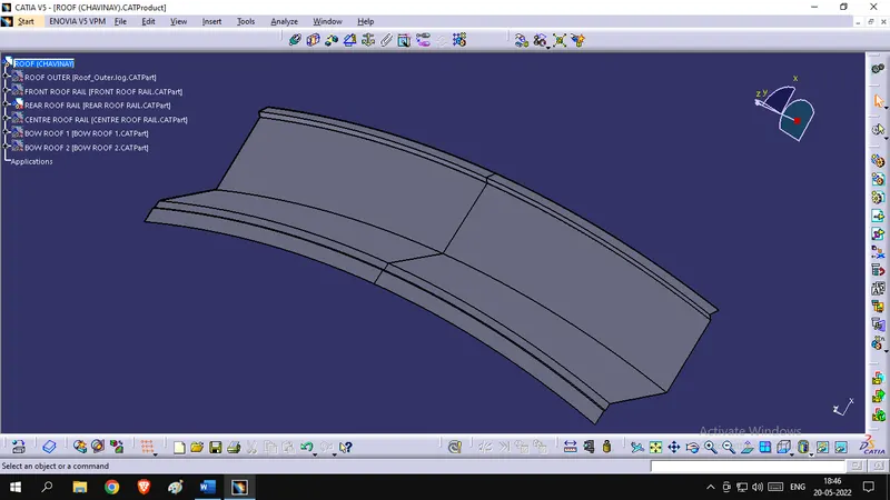
Centre Roof Rails
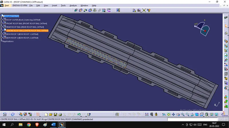
These are made and provided just for one role to play that is to give reinforcement to the roof. Increase the overall strength of the upper area of the vehicle. They help in heat distortion and also withstand snow load in countries where snowfall is common and heavy.
Bow Roofs
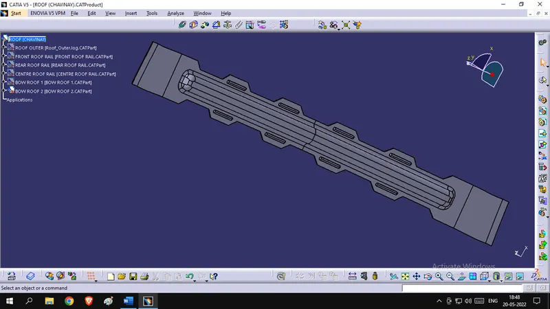
As the name suggests the, bow roofs are to support the bowing down of the roof, due to any kind of load. These too, are made for reinforcement of the roof, but are made on either side of the centre roof rail. Both the centre roof rail and the bow roofs are slightly thicker than the thickness of the roof. This is done to provide better strength.
DRAFT ANALYSIS
Any object, when designed or made in surface workbench, is required to have a certain level of drafting angle provided to it. It is the angle of slight deviation given to the walls of the product. So that the release of the obtained product, after the completion of the process is easy and hassle free.
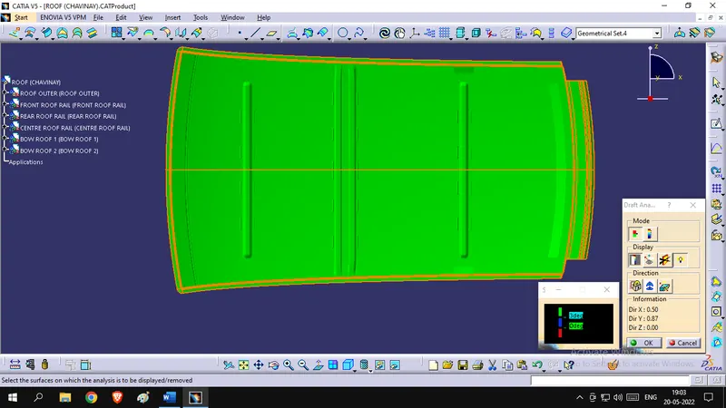
This is done in the cad software CATIA V5 as a feature which requires a tooling axis, along which the tool is pulled out after the completion of the process. Draft analysis is done to all the components separately and sometimes a set of two axis are required to do the job.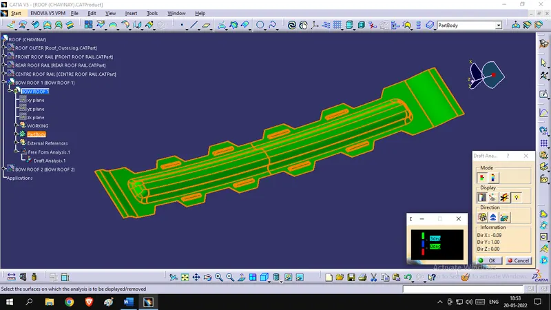
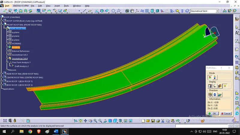
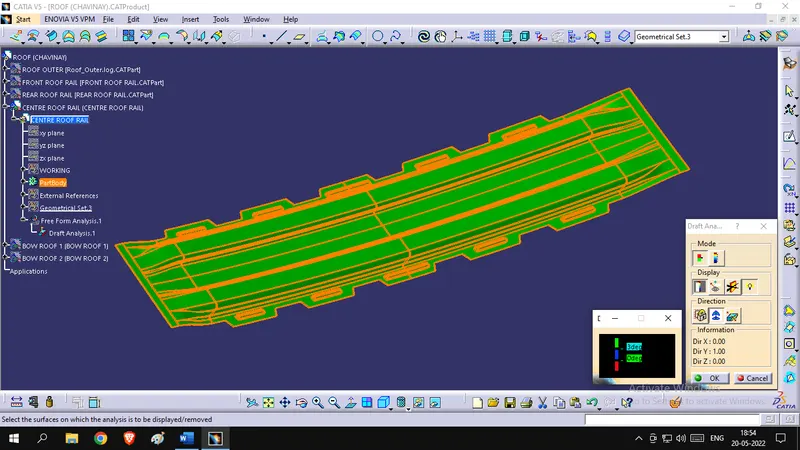
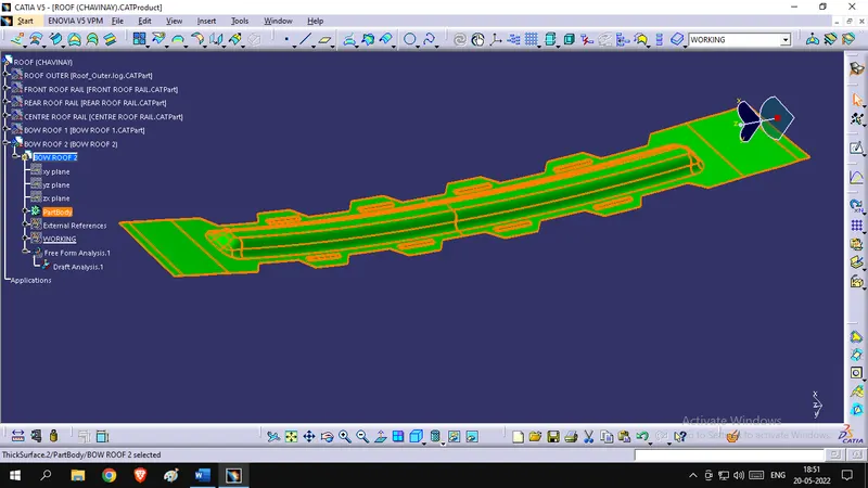
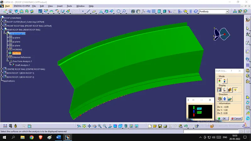
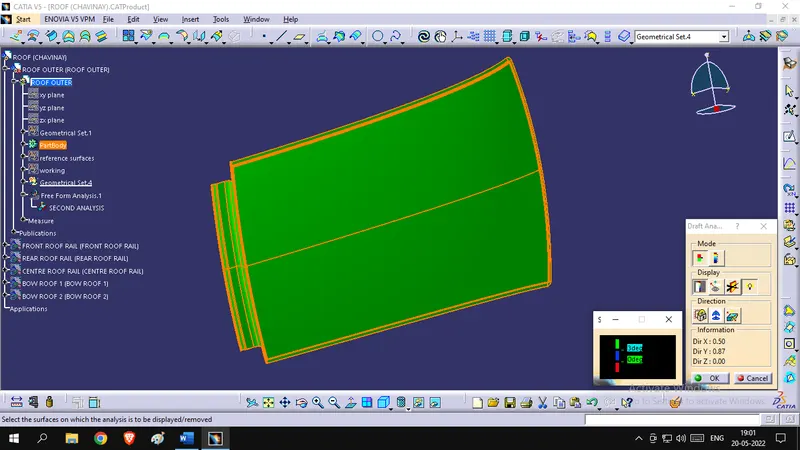
CALCULATIONS
Two main things that the roof safeguards the passenger in the cabin, apart from a crash, are from the heat of the sun and the snow weight load on itself.
Any person making or designing the roof has to consider the strength it has to withstand the above-mentioned load and weather capacity. This is done by some calculations in the heat distortion and moment of inertia side of the roof
HEAT DISTORTION ANALYSIS: -
The location of the bow roof and reinforcements are determined prior to the start of the design. This helps in reducing the work of analysis engineer for crash and snow tests. All the values are created using the formula below
Formulae: -
W= [1.73*10^ (-3) *L] + [1.85*10^ (-8) *(R^2)/t] + [1.10*10^ (-3) *1]-2.68
| FRR - BOW 1 | 2160.106 | 5700.405 | 2005.564 | 2967.187398 | 0.75 | 268.062 | 1.569021873 | |
| BOW 1 - CRR | 2160.106 | 5156.588 | 5229.415 | 5192.746167 | 0.75 | 388.578 | 2.149546295 | |
| CRR - BOW 2 | 2160.106 | 9764.51 | 4142.501 | 5817.136758 | 0.75 | 494.384 | 2.435503088 | |
| BOW 2 - RRR | 2160.106 | 14741.696 | 3258.021 | 5336.612253 | 0.75 | 402.588 | 2.202322795 | |
JUDGEMENT CONDITION: W< 2.7
Where, L = Roof Length in X Direction [mm] (Roof dimension in 0 - Y)
R = Roof Curvature = 2(Rx*Ry)/(Rx+Ry)
Rx is X curvature & Ry is Y curvature
t = Roof Plate Thickness in mm
l = Bow Roof Span in mm
Formulae: -SNOW LOAD ANALYSIS: -
Qr = [ly*t^(2)]/[a*s*[(Rx+Ry)/2] ^ (2) *10^ (-8)]
Where a = My*Lx^ (2) *10^ (-12) &
My = Y(Ly-Y)
| FRR - BOW 1 | 4744.371 | 4888.6 | 2118.712 | 0.75 | 0.824166123 | 2160.106 | 1135.462 | 353.922 | 639248.2536 | 353.922 | 493.375 | 423.6485 | 62.26411489 | |
| BOW 1 - CRR | 15338.11 | 5058.952 | 3765.39 | 0.75 | 0.989575152 | 2160.106 | 1096.991 | 493.375 | 822323.4071 | 493.375 | 599.919 | 546.647 | 81.92831244 | |
| CRR - BOW 2 | 4744.343 | 10092.732 | 4188.182 | 0.75 | 1.043344307 | 2160.106 | 1055.794 | 599.919 | 935985.8249 | 599.919 | 546.381 | 573.15 | 8.752873309 | |
| BOW 2 - RRR | - | 16612.575 | 3969.161 | 0.75 | 0 | 2160.106 | - | 546.381 | 881708.6792 | 546.381 | - | 0 | 0 | |
JUDGEMENT CONDITION: Qr >= 3.1
t = Roof Plate Thickness in mm
Ly = Distance between the front and rear roof rails on the vehicle along with 0Y in mm
Length of the roof panel with the centre point between roof rail front/rear as the front and rear reference point.
Lx = Distance between the left and right end of the roof on the roof bow in mm
(Width of the roof panel exposed on the surface.)
Y = Distance from the front Roof rail to the bow roof in mm
S = Distance for which roof Bow bears divided load in mm = L1/2 + L2/2
Ly = Geometrical moment of inertia of Roof Bow (Y Cross section) in mm4
Rx = Lateral Direction Curvature Radius of the roof panel X Cross-section on roof bow in mm
Roof panel X curvature radius of length s in side view
- All the values are taken from the model and tabulated