Roof challenge
AIM
A dumb solid body of roof CAD model is provided for which following points to be designed and analyzed are as follow,
- Extracting the styling surface and for the given car roof styling and design the essential flanges and reinforcement, namely Ditch Area, Front Roof Rail, Rear Roof Rail, Centre Roof Rail, and Bow-Roofs.
- Do a curvature study on the roof and perform calculations for Heat Distortion and Snow load criterion to determine and justify the position of the Bow-roofs.
- Finding a moment of inertia and Section Modulus for Bow Roof Rails and Centre Roof Rail.
- Perform a Draft Analysis of each reinforcement.
Introduction
An automobile roof is the portion of an automobile that sits above the passenger compartment, protecting the vehicle occupants from sun, wind, rain, and other external elements. Under the styling surface that is seen from the outside, there are many other structures under the roof that contribute to its strength and stability. The number of such reinforcement structures/supports differ with respect to the size of the vehicle. They are primarily installed on flatter areas of the roof to enhance strength.
These are the Front Roof Rail, Rear Roof Rail, Centre Roof Rail, and Bow Roof Design which are given Mastics and spot-welded to roof flanges & ditch areas and improve NVH value by increasing the strength of the roof using mastic sealants.
Design consideration of roof:
- Visibility Criteria
- Head clearance
- Curvature study
- Heat distortion and snow load criteria
- Draft analysis.
- Safety parameters
Roof Crush Test for Passenger Car:
Safety point of view vehicle roof plays a very crucial role especially roll over kind of accidents, in which vehicle tips over onto its side of the roof. And vehicle rollover crashes are the cause of many fatalities and head, neck, and spine trauma around the world.
Therefore, passenger safety is also a very important parameter in front of OEMs. It is not only a marketing strategy but also it is an obligation stipulated by international standards that are now placed in several countries, as well as a governmental requirement. For this reason, strength is a very important criterion for designing a vehicle roof.
The strength of the roof structure to occupant protection in real-world rollover crashes, requiring the maximum moving distance of the roof structure should be less than 127 mm (5 in.) when the induced load is 1.5 times the vehicle weight.
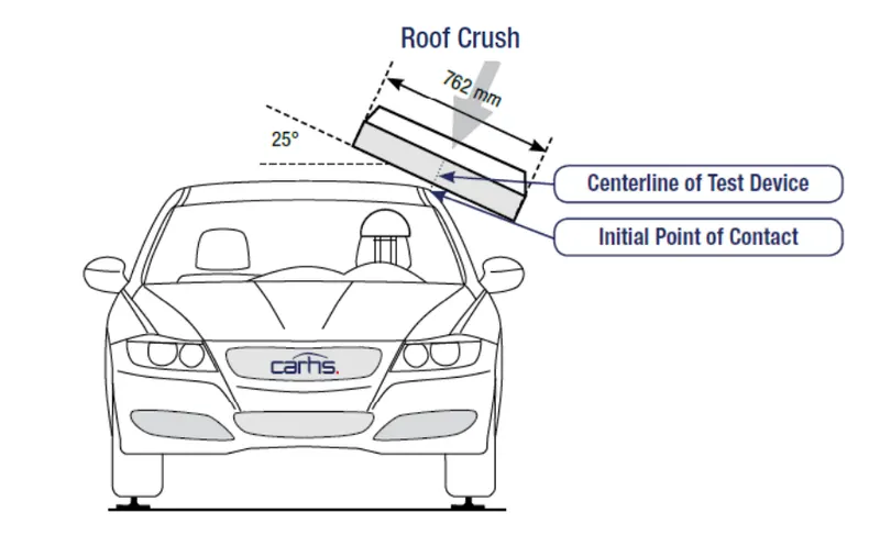
For the test, the passenger car shall be rigidly placed or positioned on a horizontal surface with the doors locked and the window closed. Furthermore, a flat, rigid block with a lower surface a rectangle measuring 30 inches wide by 72 inches long (762mm X 1829mm) shall not move more than 5 inches(127mm), measured as the distance between the original location of the lower surface of the test device and its location as the specified force level is reached, when it is used to apply a force of 1.5 times the unloaded vehicle weight (UVW) or 5000 lbs(22224N), whichever is less, to either side or forward edge of the vehicle.
This test can be conducted on either side of the roof structure, the front left or the front right side but not on both sides in one single test and still meet the requirements of the test. The rigid plate shall not move faster than 0.5 inches/second and the force applied on the plate shall not exceed the lesser of 1.5 times the unloaded vehicle weight (UVW) expressed in kilograms multiplied by 9.8 or 5000lbs (22240N).
Also, the direction of the force shall be downward and perpendicular to the lower surface of the rigid plate and such that it moves in a straight line without rotation. The duration of the test shall not exceed 120 seconds. The longitudinal axis of the plate is pitched forward at a 5 º angle as viewed from the side of the passenger car as shown in below fig..,
The lateral axis or the roll of the plate is such that it forms a 25 º outboard angle with a horizontal surface as viewed from the front of the passenger car as shown in below fig..,
Styling Surface to Extracted Surface:
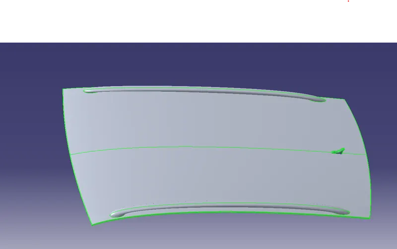
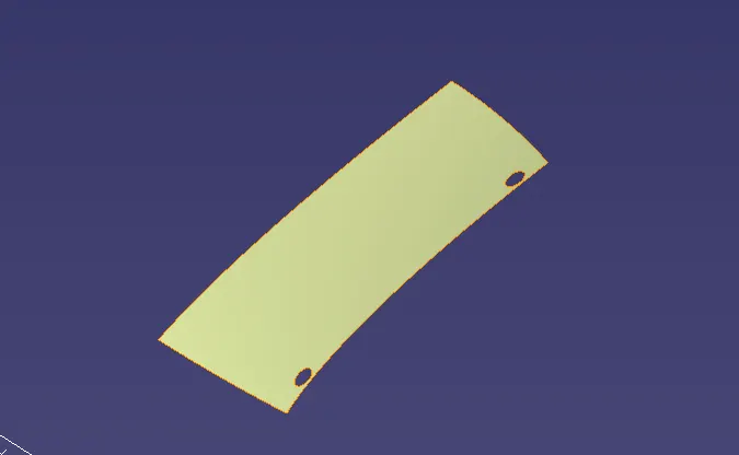
The styling team has provided the solid dump outer panel from that we are extracting the surface to model the necessary reinforcements like Ditch area, Front Roof Rail, Bow Roof Rails,Centre Roof and Rear Doof Rail.
Front Ditch Area:
From dump solid part class A surface is extracted and ditch area are developed considering the parameter specified in the following master section.
Flange of around 15mm created with the law extension command, corner relief at rear flanges and positive draft more than 3 degree considering for the drawing operation process. Overall thickness of sheet metal consider 0.75mm throughout. 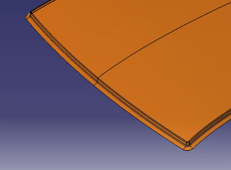
Rear Ditch Area:
Surface is offset from the outer panel to form the ditch area and with the law extension command, corner relief at rear flanges and positive draft in required degree considering for the drawing operation process. Overall thickness of sheet metal for outer panel consider 0.75mm throughout.
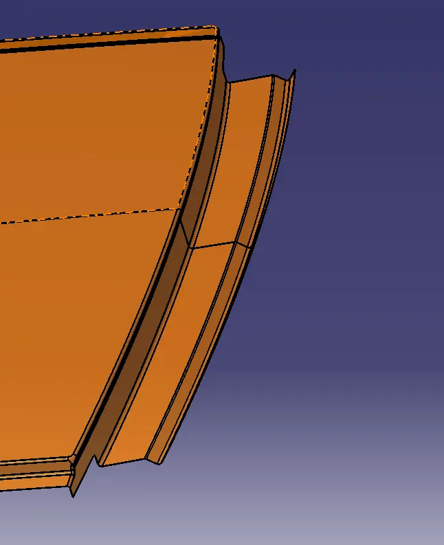
Front Roof Rail:
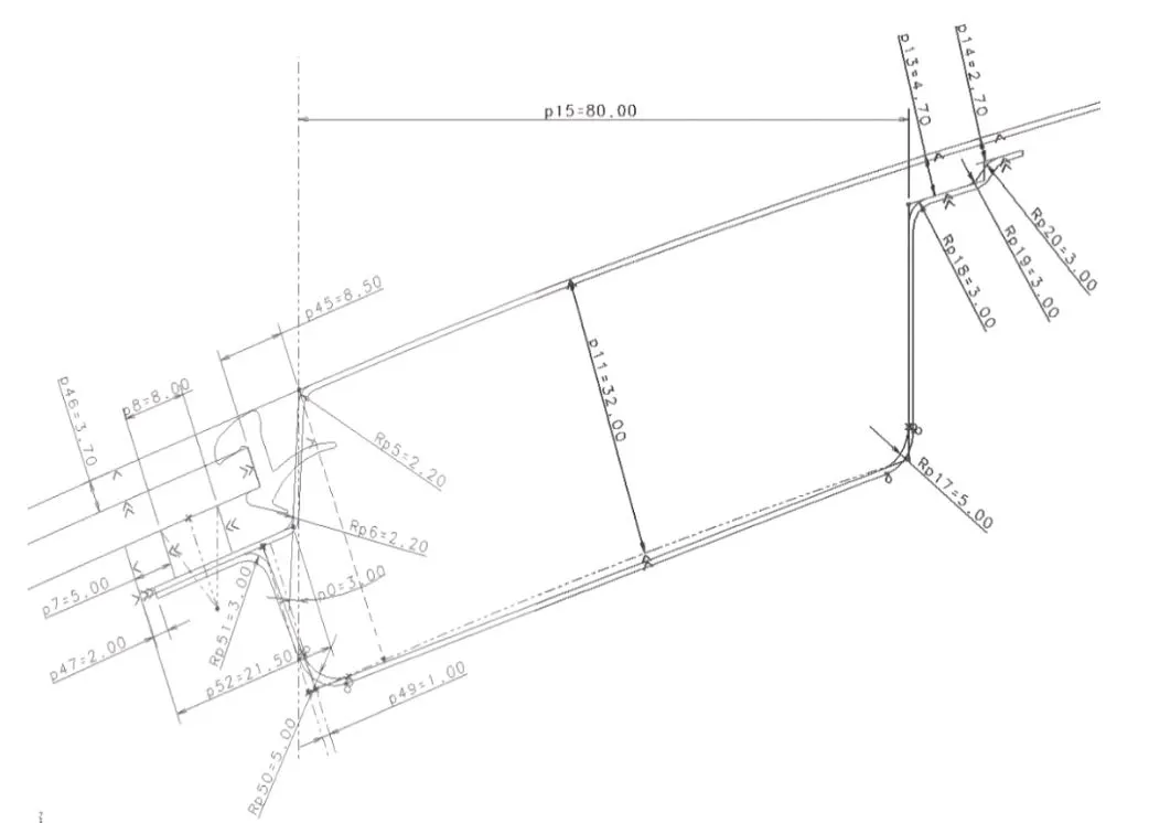
The master sketch has all the geometrical details for front roof. A space for about 21 mm is provided for windshield, rubber lining and mastic. The drawing angle is kept open for about 3degrees. The sealant requires at least of minimum 5mm gap. Whenever the inclination were provided for flanges the visibility criteria and the drawability has to be considered. The offset surface distance 32mm depends on the visibility of driver and enough head room clearance. The 80mm length depends on surface match with outer panel and also provides enough cabin clearance. On the right side of roof rail a clearance of about 3mm is given for mastic. Corner relief are given to deviate the stress concentration point.
Master Section for Front roof rail.
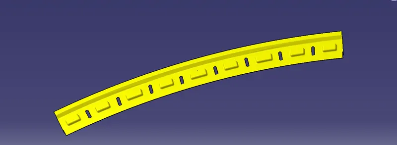
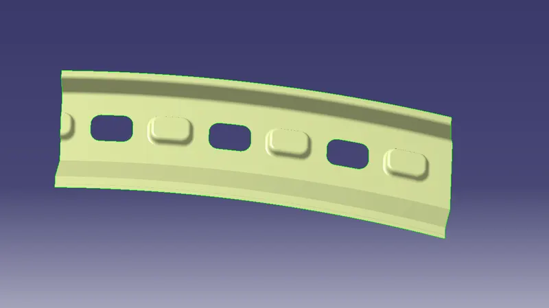
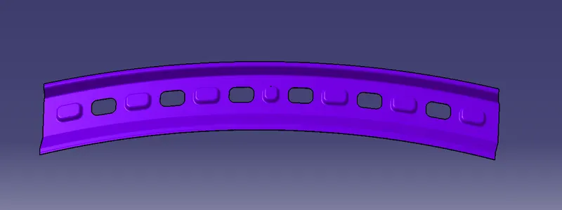
Rear Roof Rail:
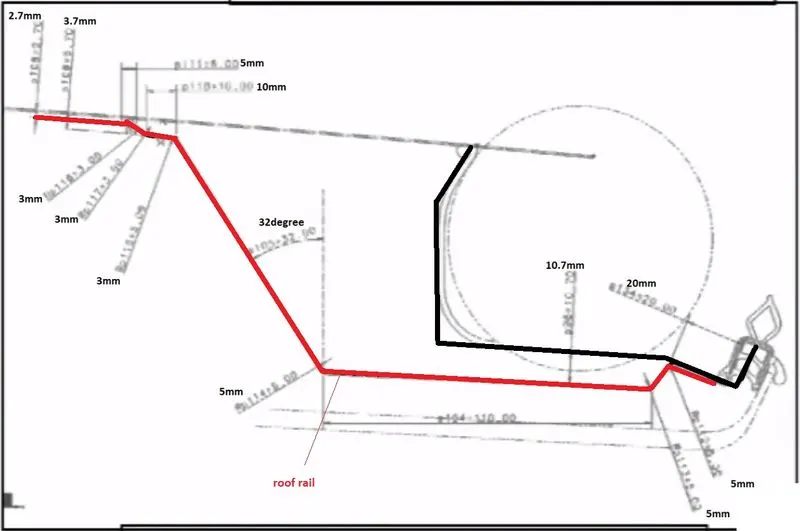
This part joins the back door and the body side outer. The rear roof provides enough space for back door hinge placement. The field of vision and head room clearance are to be considered while dimensioning.
Centre Roof Rail:
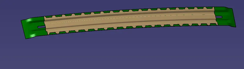
Centre roof rail is provided to effectively support the flat area of the roof as it is more susceptible to failure under the action of the load. Usually, the centre reinforcement roof rail will be placed at the centre of the roof connecting the B pillar support structure which results in added support in the roll-over test. The thickness of the centre bow roof is 0.75 mm thickness
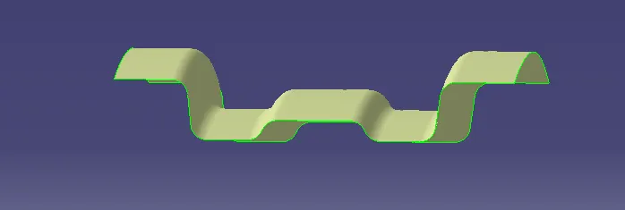
create cutout in the conter roof rail.
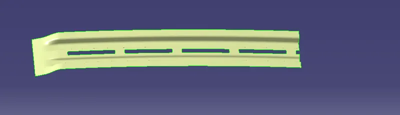
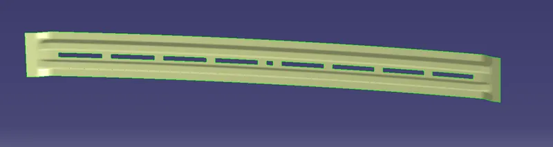
Reinforcement for Center roof rail.
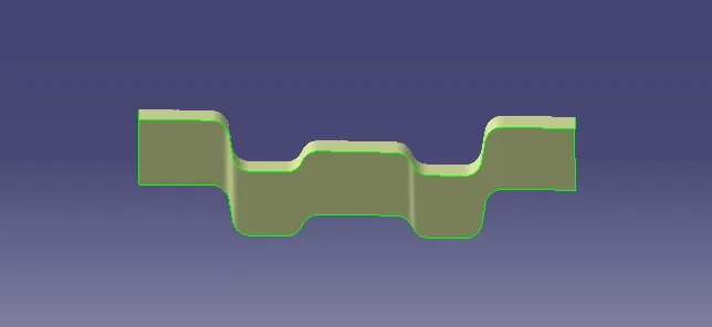
create mastics in the reinforcement.
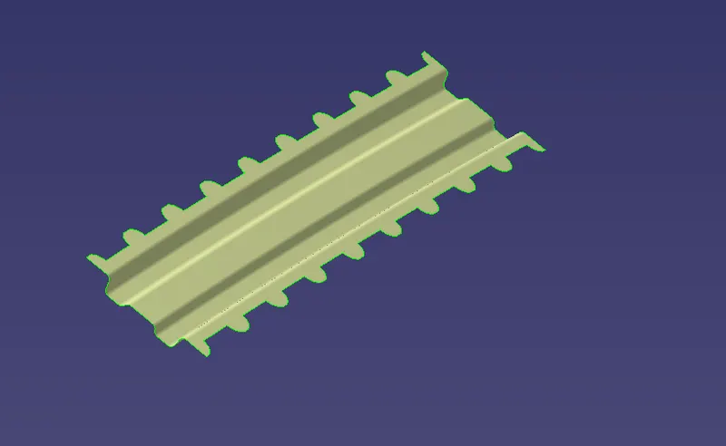
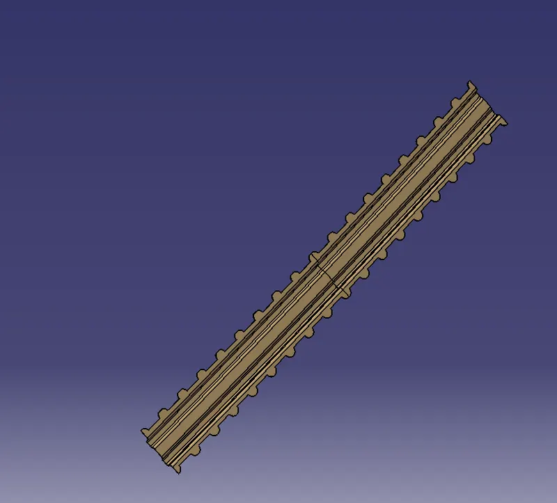
Center roof rail and reinforcement
Bow Roof Rail:
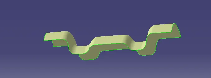
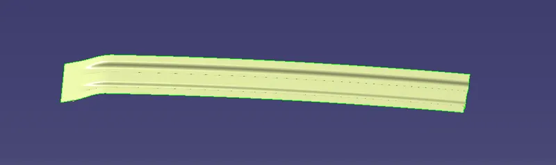
The cottages were built with the bow roofs to facilitate enough flexural stability while in case of strong winds. The similar situation is happening in the automotive roof. To control strong induced current of winds the bow roofs were introduced. These bow roof’s shape decides their resistance towards the bending load. I have given I section shape to the bow roofs to resist bending moments created along the length of bow. Since the web section will not allow the flanges to bend during the snow load or roll over scenarios.
- 2 bow roofs are created to give strength to the roof.
- Follow the same method as with the center reinforcement to create the bow roof.
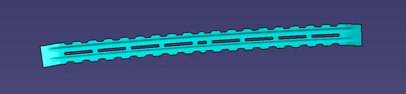
- Now, after the bow roof is created. The mastic points need to be created.
- Use the parallel curve and connect the outer edge and parallel curve to cut the element

Mastic Sealants:
Bow Roof Rails and Centre Roof Rail are joined with the help of Mastic Sealant. Here we cant's use the Spot welding because it damages the A class area of the Roof. So, the mastic sealant is used in this area.
Roof rails:
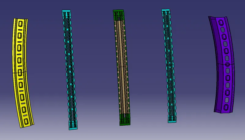
Multi views of Roof assembly
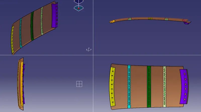
Roof Assembly.
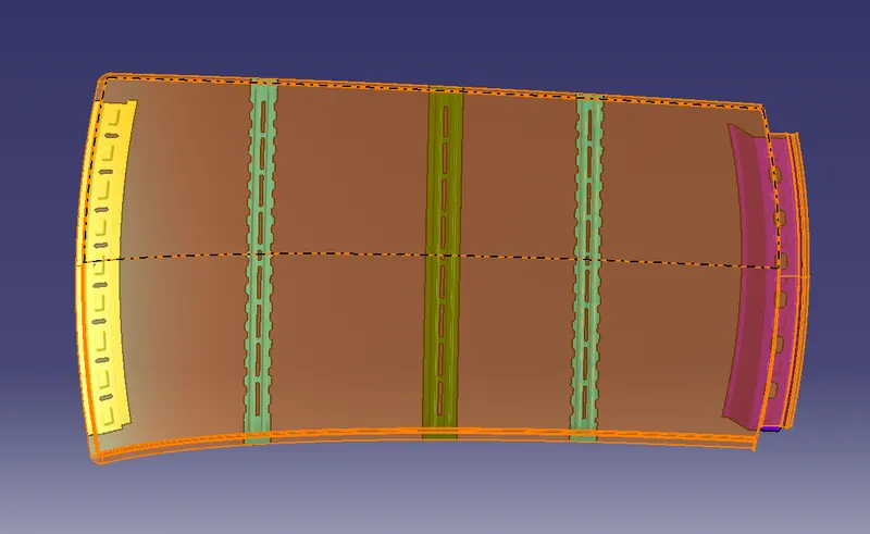
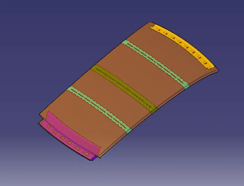
Heat distortion calculation
The material softens under increased temperature conditions. While applying load at this state makes the material much vulnerable to static loads. So to formulate this scenario the heat distortion criteria is introduced. The formula for heat distortion criteria is
W = [1.73 x 10^ (-3) x L] + [1.85 x 10^ (-8) x (R^2)/t] + [1.10x10^ (-3) x l] -2.68
judgement condition
OK< 2.7
Where
L = Roof Length in X-Direction [mm] (Roof dimension in 0-Y)
R = Roof curvature
R = 2(Rx*Ry)/ (Rx+Ry)
Rx = X curvature
Ry = Y curvature
t = Roof plate thickness [mm]
l = Bow Roof Span [mm]
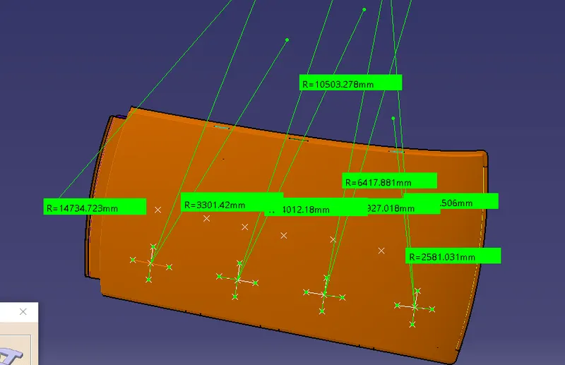
Values of curvature in X direction and Y direction (Rx and Ry)
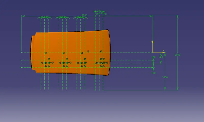
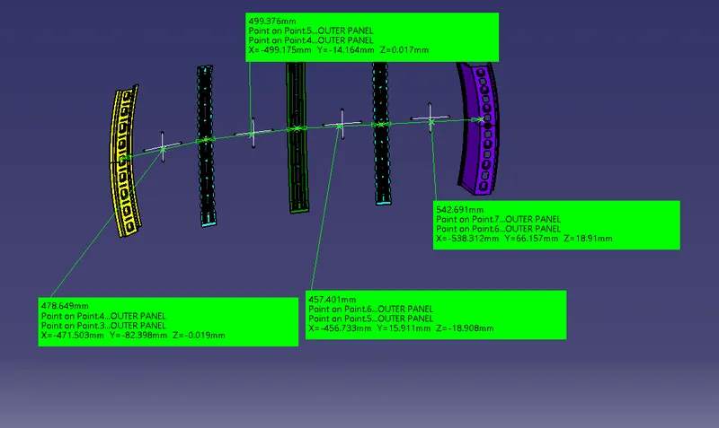
length of roof span
L= 2135.9 mm
t=0.75
Heat Distortion Result
| BAY | L | t | Rx | Ry | R | I | W | CONDITION |
| 1 | 2135.9 | 0.75 | 5820.5 | 2499.2 | 3496.903398 | 409.995 | 1.767733723 | OK |
| 2 | 2135.9 | 0.75 | 4906.9 | 6498.4 | 5591.610735 | 366.883 | 2.189909029 | OK |
| 3 | 2135.9 | 0.75 | 3994.3 | 10596 | 5801.608301 | 409.431 | 2.295728019 | OK |
| 4 | 2135.9 | 0.75 | 3266.2 | 14982 | 5363.181947 | 367.869 | 2.129268008 | OK |
Here Lets consider space between two roof rails is Bay.
The optimum range needed to fulfill this criteria is less than 2.7. So by inferring from the above calculated values the W seems to be in good optimum range. Hence all the bow roofs and rails OK to proceed.
SNOW LOAD CALCULATION:
Qr = [Iy x t2] / [α x s x [(Rx + Ry)/2]2 x 10-8]
Where
α = My x Lx2 x 10-12, My = Y(Ly-Y)
Judgement condition = Qr ≥ 3.1
250 ≤ s ≤ 380
t = Roof plate thickness [mm]
Ly = Distance between the front and rear roof Rails on the Vehicle along with 0Y [mm]
Length of Roof panel with the center point between Roof rails Front /Rear as the reference point of the front and the rear.
Lx = Distance between the Left and Right end of the roof on the Roof BOW [mm]
Width of the roof panel exposed on the surface.
Y = Distance from Front Roof Rail to Roof BOW [mm]
s = Distance for which Roof BOW bears divided load [mm]
s = L1/2 + L2/2
Iy = Geometrical moment of inertia of Roof BOW (Y cross-section) [mm4]
Rx = Lateral direction curvature radius of roof panel Y cross-section on Roof BOW [mm]
Roof panel curvature Radius of the Length Lx in Front view
Ry = Longitudinal Direction curvature radius of the Roof panel X cross-section on Roof BOW [mm]
Roof panel X curvature radius of length s in Side view
SECTION MODULUS CALCULATON
Section Modulus:
Section modulus is a geometric property for a given cross-section used in the design of beams. Other geometric properties used in design include area for tension, radius of gyration for compression, and moment of inertia for stiffness. The Section modulus is defined as
S=I/y
Where
S = Section Modulus
I = Moment of Inertia
y=distance between neutral axis and extreme end of the section
Front Roof Rail
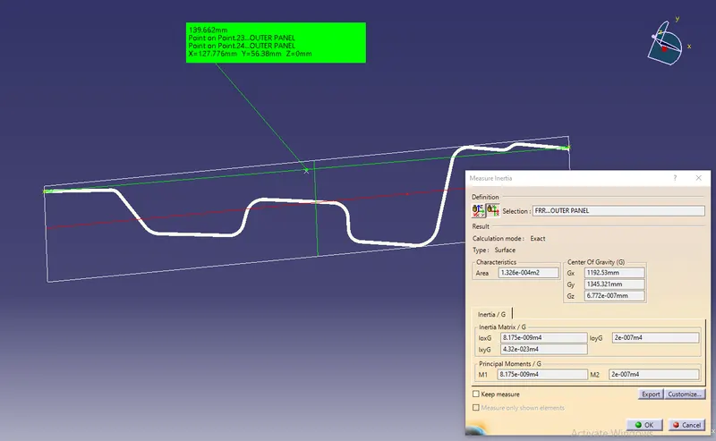
S=I/y
I=8.175x10^-9 m^4 = 8.175 x 10^3 mm^4
y= 127.776/2
y = 63.888
S=I/y
S= 127.95 mm^3
Section modulus for Front Roof rail is 127.95 mm^3
Rear Roof Rail
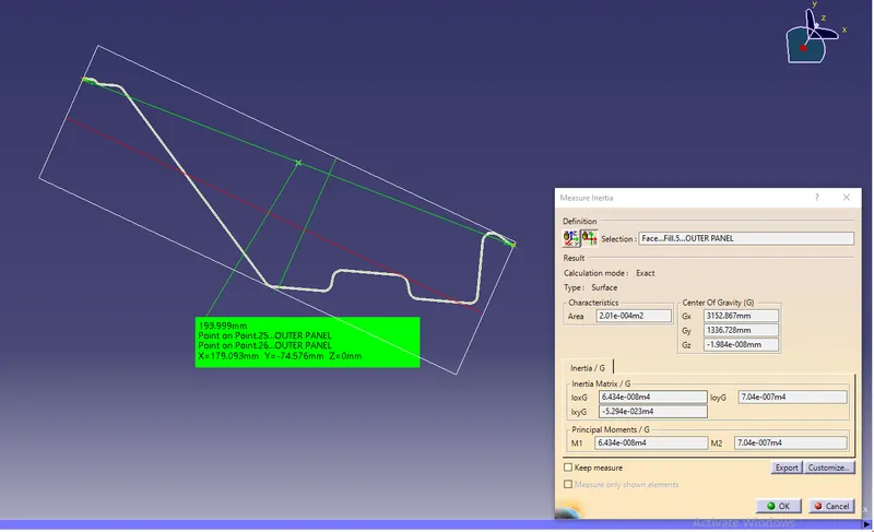
S=I/y
I=6.434x10^-8 m^4 = 6.434 x 10^4 mm^4
y= 179.093/2
y = 89.546
S=I/y
S= 722.92 mm^3
Section modulus for Rear Roof rail is 722.92 mm^3
Center roof rail with reinforcement section
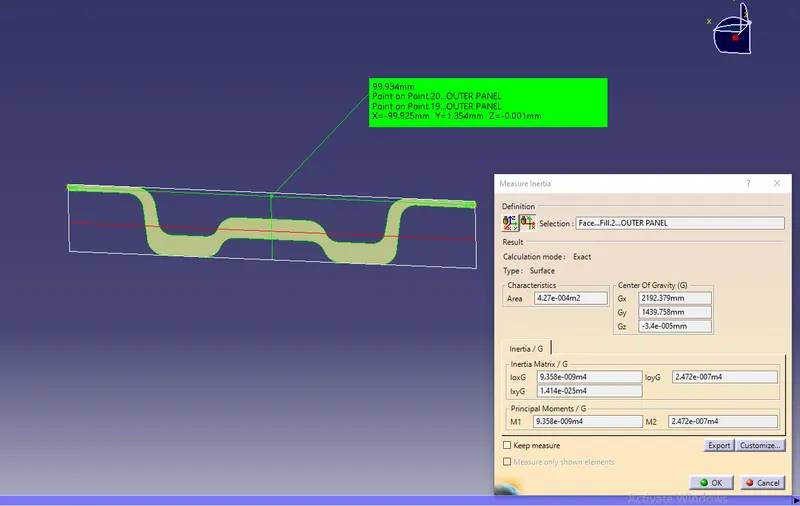
S=I/y
I=9.358x10^-9 m^4 = 9.358 x 10^3 mm^4
y= 99.925/2
y = 49.962
S=I/y
S= 187.302 mm^3
Section modulus for Center Roof rail is 177.302 mm^3
Bow roof 1 section:
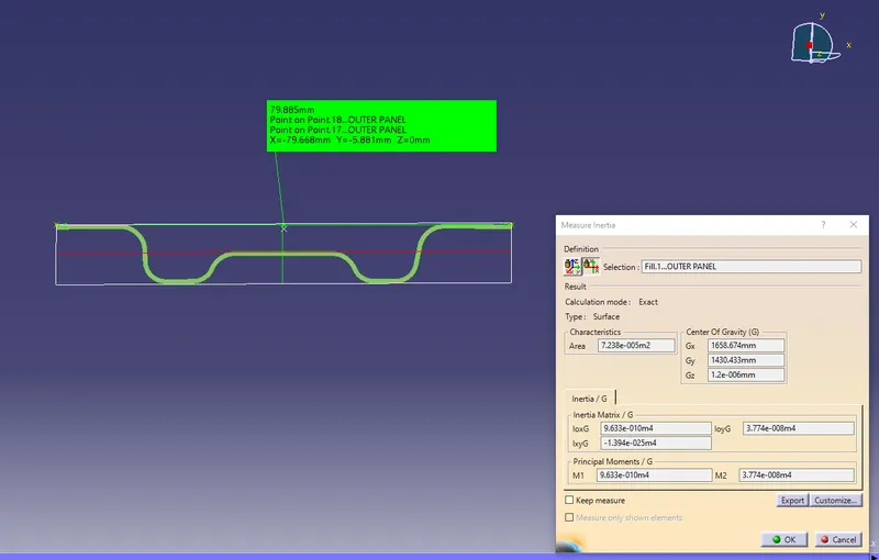
S=I/y
I=9.633x10^-10 m^4 = 9.633 x 10^2 mm^4
y= 79.668/2
y = 39.834
S=I/y
S= 24.182 mm^3
Section modulus for Bow Roof 1 is 24.182 mm^3
Bow roof 2 section
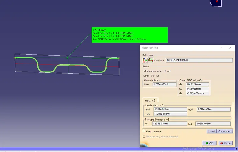
S=I/y
I=8.535x10^-10 m^4 = 8.535 x 10^2 mm^4
y= 72.839/2
y= 36.4195
S=I/y
S= 24.797 mm^3
Section modulus for Bow Roof 2 is 24.797 mm^3
Create curvature in roof surface by using sketch to create intersecting lines and mark point center of the roof and project in the roof panel.
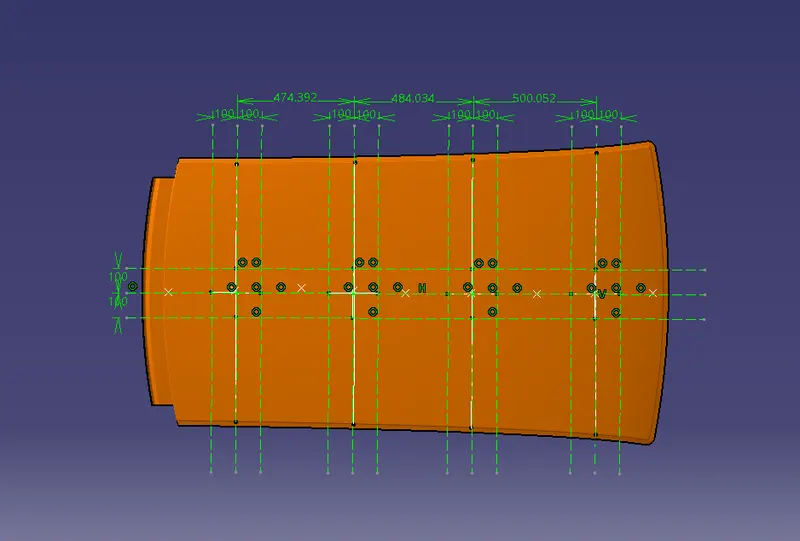
Measuring radius of curvature in center area of roof in lateral and longidutinal direction(Rx and Ry)
Lx values ( Distance between the Left and Right end of the roof on the Roof BOW)
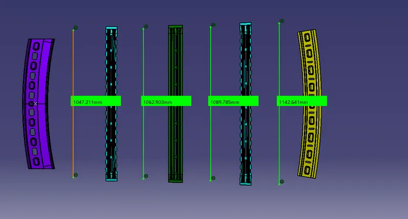
Snow load result
| BAY | Iy | l | s | t | Rx | Ry | Lx | Ly | Y | My | ALPHA(α) | L1 | L2 | S | Qr |
| 1 | 963.3 | 79.668 | 12.09142943 | 0.75 | 4571.664 | 2542.999 | 1142.641 | 1965.723 | 538.312 | 768392.4702 | 1.003235074 | 538.312 | 456.833 | 497.5725 | 27.11011007 |
| 2 | 935.8 | 99.925 | 9.365023768 | 0.75 | 3773.618 | 6289.588 | 1089.785 | 1965.723 | 456.733 | 689205.5297 | 0.818522091 | 456.733 | 499.175 | 477.954 | 16.79698265 |
| 3 | 853.5 | 72.839 | 11.7176238 | 0.75 | 4268.37 | 10983.467 | 1062.903 | 1965.723 | 499.175 | 732064.0979 | 0.8270587758 | 499.175 | 471.503 | 485.339 | 6.500026307 |
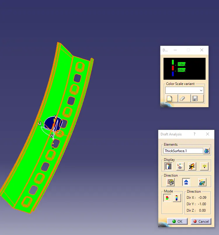
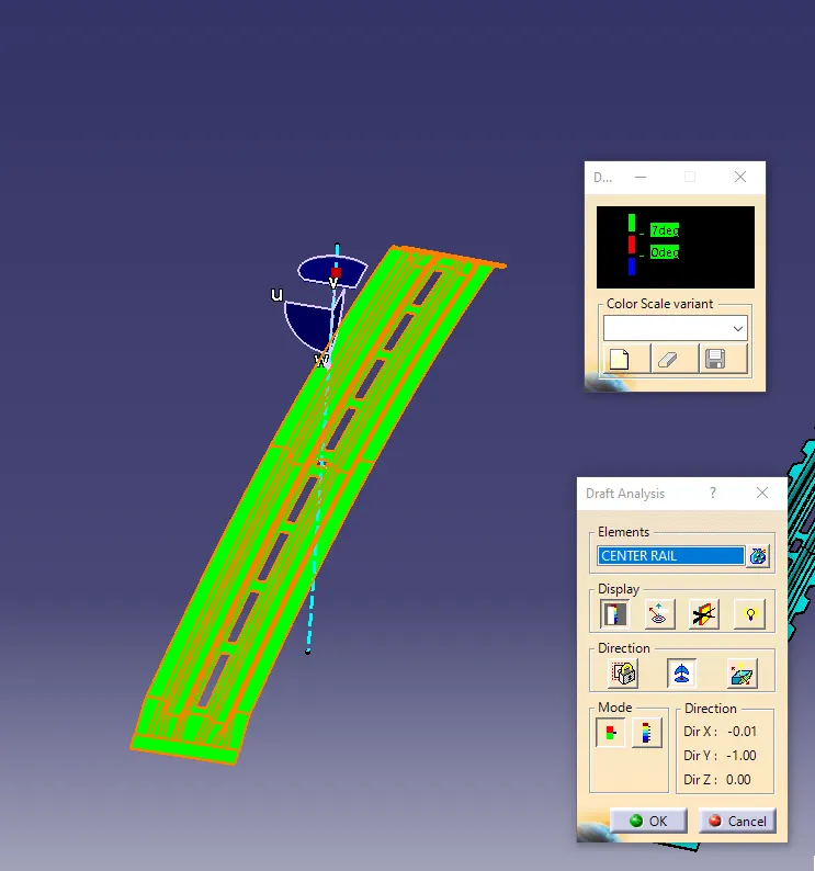
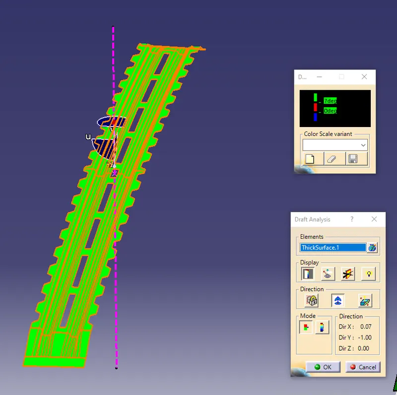
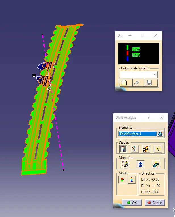
DRAFT ANALYSIS:
The draft analysis is done by the all the compoents and check the passing the criteria.
Roof panel
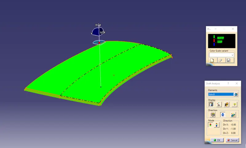
Front Roof Rail
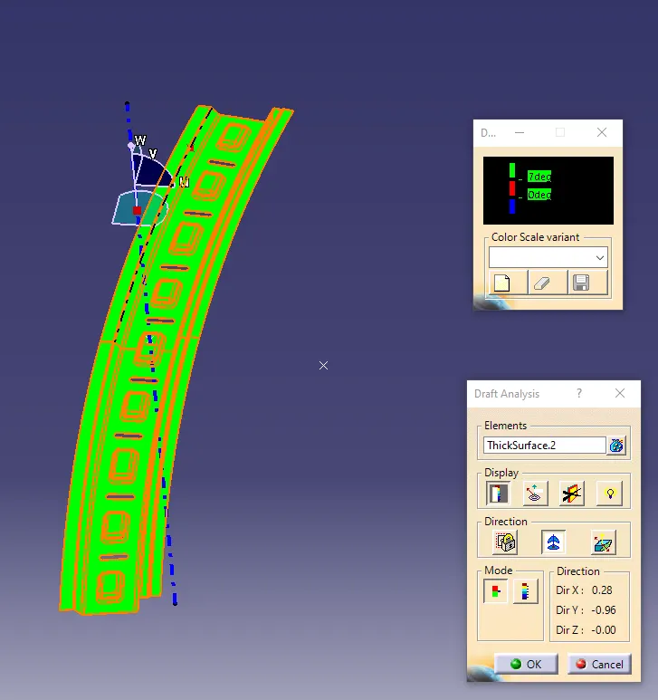
Rear Roof Rail
Center Roof Rail
Bow Roof 1
Bow Roof 2
Conclusion
Here, developed the Roof assembly form the given stylying surface with appropriated dimensions. Checked draft analysis for roof and its all roof rails.Performed calculations of Heat distortion and snow load condiotion with curvature study.