Roof challenge
an automobile roof is the portion of an automobime thats sit above from the passenger compartment
its protecting the vehicle fron the sun , wind, rain and other external climates
its consitst of of roof outer panel , front roof rail, rear roof rail and bow roof
PROCEDURE :
make assembly prt and save as roof assembly
ROOF OUTER PANEL :
open the given roof file
extract the outer surface and untrim the surface
trim the extra portions of outer surface
bridge curve used to make 2 curves at the outer side and trim it
make surfaces at two sides at an angle of 3mm
again make another surface in two sides at 21.5mm
bride curve apply on the corver side of front
studio surface option used to make corner surface
apply edge blend on the the edges at 2.2mm
make surface at the rear side at an agle of 7deg and 15mm
make another surface at 45mm in downward
make surface horizondal at 55mm
make surface at angle 0f 25 to rear side
make surface at 20deg and 25mm in upward direction
trim the outer side of rear panel bu using new datum plane
sew all surfaces
extend all surface at perticular distance in the mirroring direction
trim the surfaces by using refference of X-Y plane
mirror surfaces by using mirror geometry at x-y mirror plane
sew maked and mirror surface
thicken the all surface at 0.75mm in downward direction
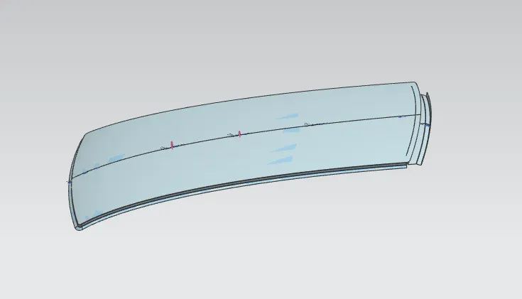
FRONT ROOF RAIL :
open the given roof file
extract the outer surface and untrim the surface
trim the extra portions of outer surface
make surface at offset distance of 31.5mm
law extension used to make surface in front side at an angle of 25mm
make surface that offsets 1.7mm from side surface of outwr pannel
trim and extend option used to correcting the outer porsions of surface
make line at 80mm and trim the 30mm offset surface
make another surfaces at 1.7 , 5mm distance in downward
trim the surface at 10mm and 5mm in rear side
surface studio used to make the angle surfaces in the trimed portions
sew all surfaces
blend the surface at 5mm in bottom side and 3mm in remaining sides
extend all surface at perticular distance in the mirroring direction
trim the surfaces by using refference of X-Y plane
mirror surfaces by using mirror geometry at x-y mirror plane
sew maked and mirror surface
thicken the all surface at 0.75mm in upward direction
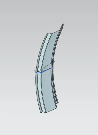
REAR ROOF RAIL :
open the given roof file
extract the outer surface and untrim the surface
trim the extra portions of outer surface
offset the surface 11.5mm from the outer panel
trim the surface at 80mm
make offset surface at 2.7 and 3.7
law extrude the surface at 32 deg and trim and extrude it
trim the 37mm surface at 10mm
law extrude the surface at 65 deg and trim and extrude it
offset the outer pannel to 0.75
law extrude the surface at 65 deg in the rear side and apply trim and extrude
sew all surfaces
blend the surface at 5mm in bottom side and 3mm in remaining sides
extend all surface at perticular distance in the mirroring direction
trim the surfaces by using refference of X-Y plane
mirror surfaces by using mirror geometry at x-y mirror plane
sew maked and mirror surface
thicken the all surface at 0.75mm in upward direction
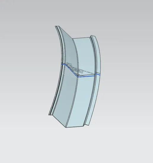
CENTER ROOF RAIL :
open the given roof file
extract the outer surface and untrim the surface
trim the extra portions of outer surface
create a datum plane at the middle portion
make a line by using datum plane
make offset suface at 20mm
make offset suface at 16.5mm and 11.5
make offset surface at 6.5mm and 7.25mm
offset the line upto 5.5 mm in both sides and trim the 16.5mm and 11.5mm offset surface
both trim surfaces can be law extruded at 7deg in both sides
trim and extruded used to triming extra portion
offsets the lines upto 16mm in the two surfaces in 16.5 mm surface
offsets the lines upto 16mm in the two surfaces in 20 mm surface
trim the surfaces by using offseted line
law extruded the trimed surfaces at 7 deg to 6.5mm offset surface
trim and extrude used trim extraa portions
law extruded the trimed surfaces at 7 deg to 7.25mm offset surface
trim and extrude used trim extraa portions
offset the line upto 16mm in the 6.5mm offset surface in both sides
trim the the surfaces by using offseted line
sew all surfaces in 2 sews
edge blend use in all edges at 2.2mm
extend all surface at perticular distance in the mirroring direction
trim the surfaces by using refference of X-Y plane
mirror surfaces by using mirror geometry at x-y mirror plane
sew maked and mirror surface
thicken the all surface at 0.75mm in upward direction
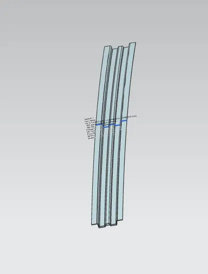
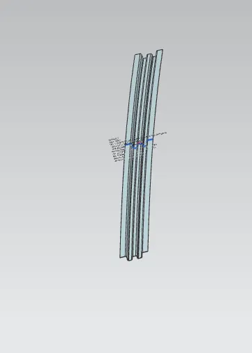
FRONT BOW ROOF RAIL:
open the given roof file
extract the outer surface and untrim the surface
trim the extra portions of outer surface
create a datum plane at the middle portion
create a datum plane at 350 from middle plane
make a line by using datum plane
make offset suface at 20mm
make offset surface at 13.5mm
make offset surface at 6.5mm
make line of 10mm in offset surface 13.5mm and trim it
etrude the surface downward at 7deg in both sides
trim and etrude is used to trim the extra portions surface
offset the line upto 15mm in the both surface in 20mm offset surface
etrude the surface downward at 7deg in both sides
trim and etrude is used to trim the extra portions surface in 6.5 offset surface
extend all surface at perticular distance in the mirroring direction
trim the surfaces by using refference of X-Y plane
mirror surfaces by using mirror geometry at x-y mirror plane
sew maked and mirror surface
thicken the all surface at 0.75mm in upward direction
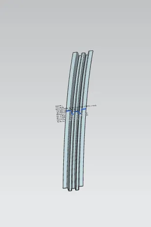
REAR BOW ROOF RAIL :
open the given roof file
extract the outer surface and untrim the surface
trim the extra portions of outer surface
create a datum plane at the middle portion
create a datum plane at 400mm from middle plane
make a line by using datum plane
make offset suface at 20mm
make offset surface at 13.5mm
make offset surface at 6.5mm
make line of 10mm in offset surface 13.5mm and trim it
etrude the surface downward at 7deg in both sides
trim and etrude is used to trim the extra portions surface
offset the line upto 15mm in the both surface in 20mm offset surface
etrude the surface downward at 7deg in both sides
trim and etrude is used to trim the extra portions surface in 6.5 offset surface
extend all surface at perticular distance in the mirroring direction
trim the surfaces by using refference of X-Y plane
mirror surfaces by using mirror geometry at x-y mirror plane
sew maked and mirror surface
thicken the all surface at 0.75mm in upward direction
CURVATURE STUDY ON THE ROOF:
heat distortion study plays an importtant role in sheet metal design
Bow roof preduction formula
heat distortion criteria:
W = [1.73 x 10^(-3) x L] + [1.85 x 10^(-8) x (R^2)/t] + [ 1.10x10^(-3) x l] - 2.68
Where ,
L = Roof Length in X-Direction[mm](Roof dimension in 0-Y)
R = Roof curvature
R = 2(Rx*Ry)/(Rx+Ry)
Rx = X curvature
Ry = Y curvature
t = Roof plate thickness [mm]
l = Bow Roof Span [mm
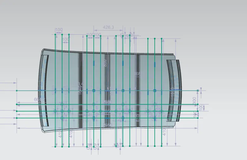
make oy axis and offset line upto 300mm
again offset the 100mm in both direction
make a point in between two roof rail
make line on the point and offsets upto 100mm in both direction
make points on the lines intersecting point and projected into the outer panel
make 2 arc on by using points
measure all needed parameters
apply all values to the given formula
calculation is given in table:
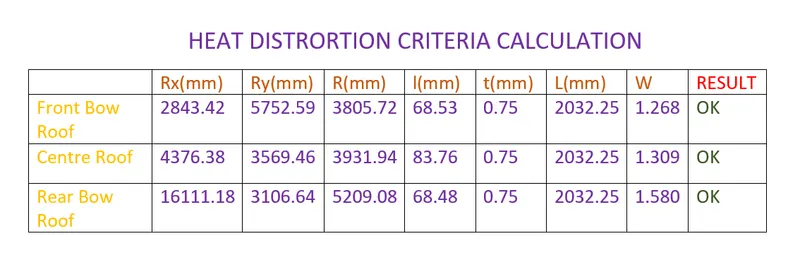
in a above calculation all are obeying the conditions
snow load criteria:
snow load criteria study is done to check the durability of roof to withstand snowfall
snow load preduction formula:
Qr = [Iy x t2] / [α x s x [(Rx + Ry)/2]2 x 10-8]
Where
α = My x Lx2 x 10-12
My = Y(Ly-Y)
t = Roof plate thickness [mm]
Ly = Distance between the front and rear roof Rails on the Vehicle along with 0Y[mm]
Length of Roof panel with the center point between Roof rail Front /Rear as the front and rear reference point.
Lx = Distance between the Left and Right end of the roof on the Roof BOW [mm]
The width of the roof panel is exposed on the surface.
Y = Distance front Front Roof Rail to Roof BOW[mm]
s = Distance for which Roof BOW bears divided load [mm]
s = L1/2 + L2/2
Iy = Geometrical moment of inertia of Roof BOW (Y cross-section )[mm4]
Rx = Lateral direction curvature radius of roof panel Y cross-section on Roof BOW [mm]
Roof panel curvature Radius of the Length Lx in Front view
Ry = Longitudinal Direction curvature radius of the Roof panel X cross-section on Roof BOW [mm]
Roof panel X curvature radius of length s in Side view
make oy axis
again offset the 100mm in both direction
make a point in between two roof rail
make line on the point and offsets upto 100mm in both direction
make points on the lines intersecting point and projected into the outer panel
make 2 arc on by using points
measure all needed parameters
apply all values to the given formula
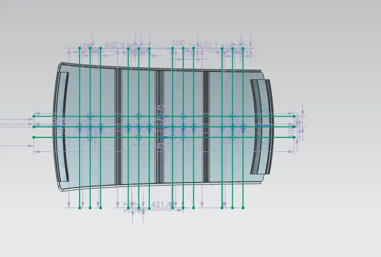
calculation is given in table:
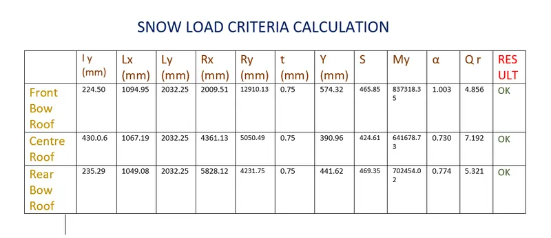
in a above calculation all are obeying the conditions
section inertia of roof rails :
front roof rail:
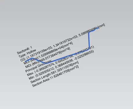
front bow roof rail :
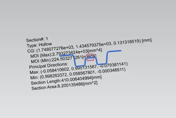
centre roof rail :
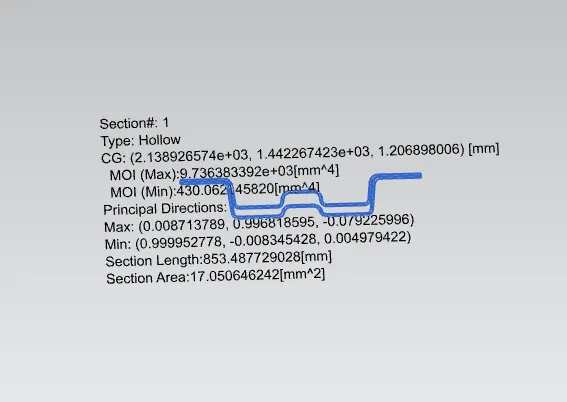
rear bow roof rail :
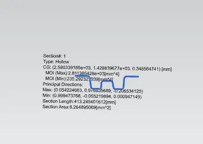
rear roof rail:
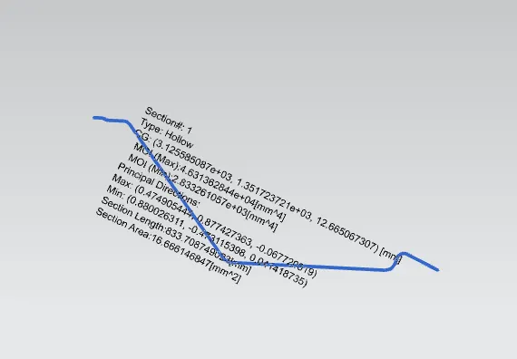
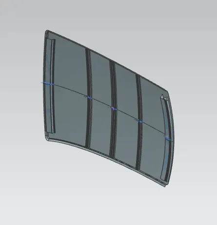
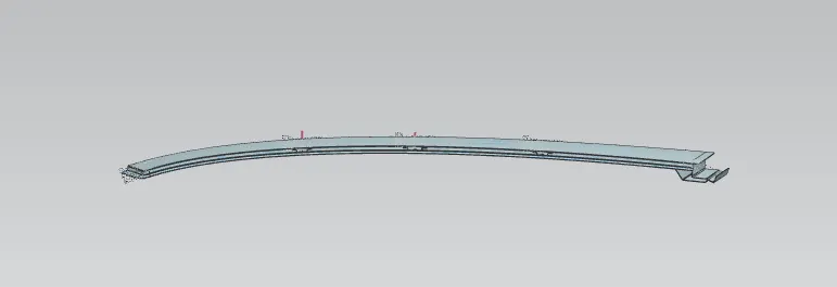
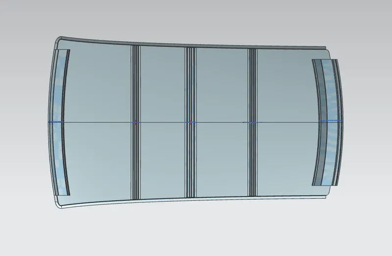
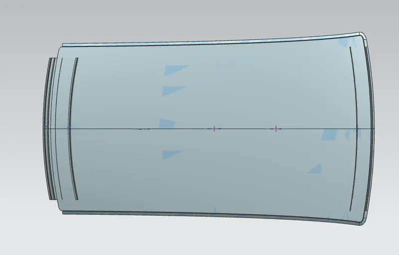
views of roof model:
GOOGLE DRIVE LINK:
https://drive.google.com/file/d/1Pp27GI0H6YTnZ0YsxYR9w07VansZ3wza/view?usp=sharing
https://drive.google.com/file/d/1Pp27GI0H6YTnZ0YsxYR9w07VansZ3wza/view?usp=sharing
conclusion:
the design of roof, front roof rail , rear roof rail, bow roofs and centre roof s by following given master sections with help of design parameter