Roof challenge
Design of Roof and its Reinforcements
The roof is the topmost assembly in the vehicle which not only gives a Styling look to the vehicle also has some safety considerations during roll-over accidents.
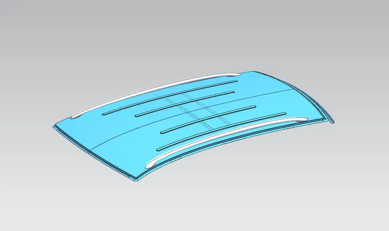
These are the following reinforcements used in the roof for supporting and strengthing the roof.
- Front Roof Rail
- Bow Roof Rail I and II
- Center roof rail and Reinforcement
- Rear roof rail
The dimensions and numbers of Bow roofs are varied based on the type of car that we are designing for.
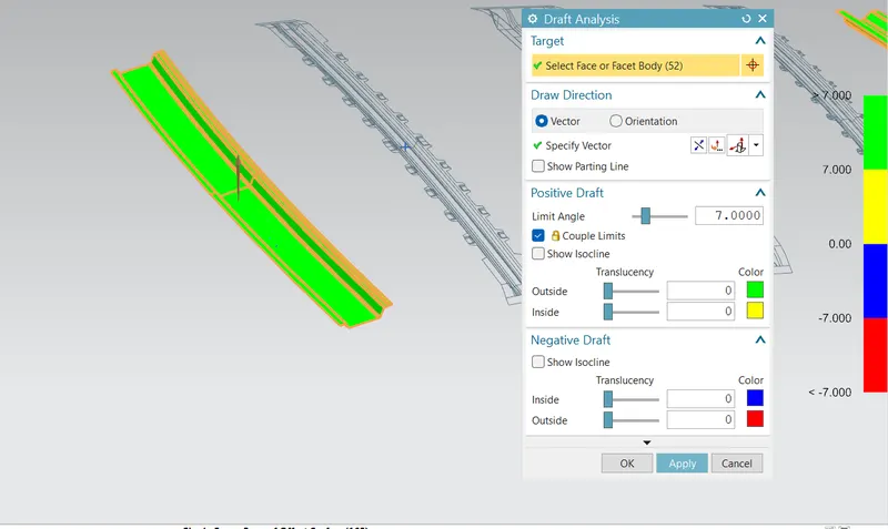
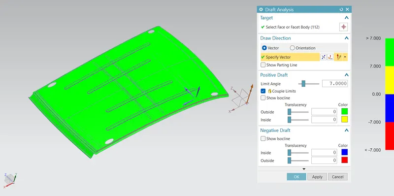
The design should meet the manufacturing standard for sheet metal that the draft should be in the positive direction of the pulling direction, as negative drafts cannot be manufactured.
Inputs Received:
1. Class A of roof
2. Mastersections of bow roof rails
3. Curvature study data
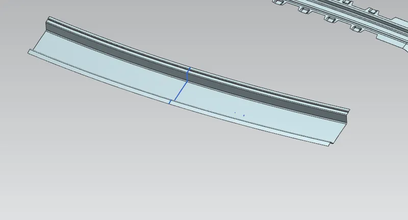
Front Roof Rail:
Front roof rail connects windshield, headliner, and roof. It is also welded with A-pillar. The dimensions of the front roof rail are very important as it gives the headroom clearance and visibility for the driver.
Draft analysis:
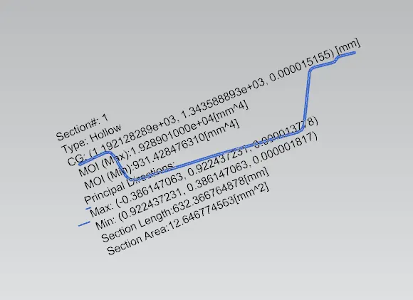
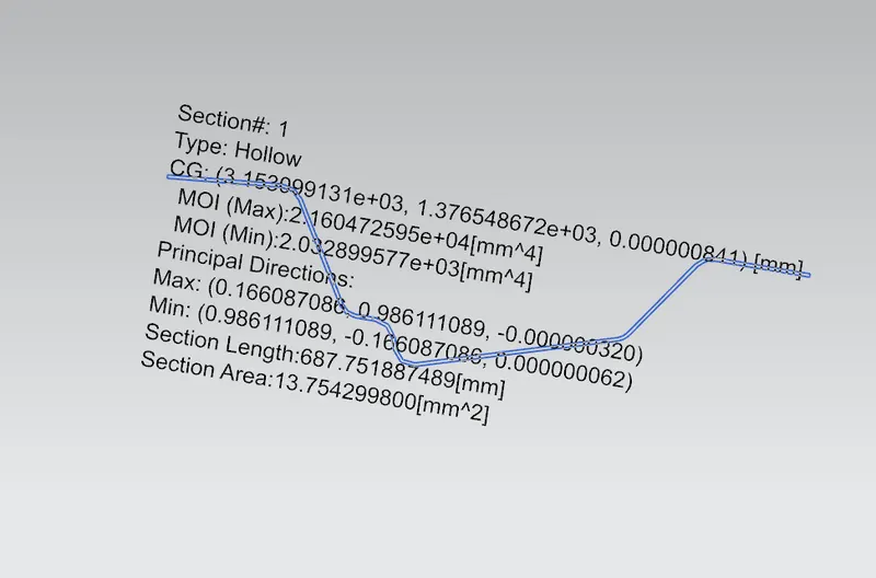
Section Inertia Analysis:
Bow Roof Rail I:
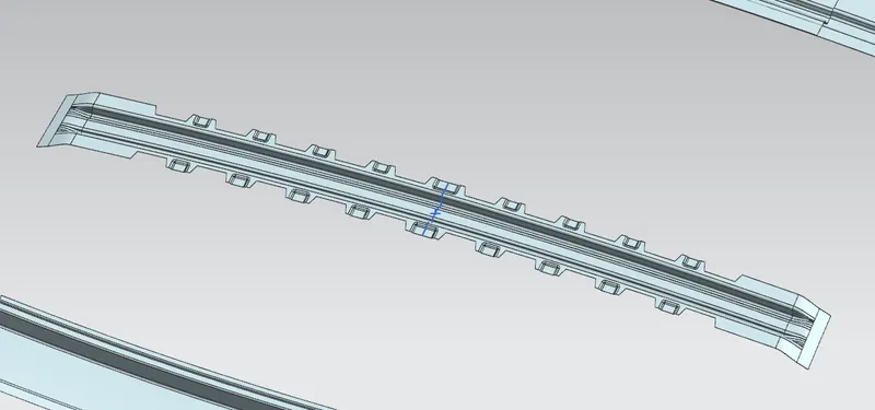
The bow roof rail is assembled with the roof with mastic sealants at the mastic points and welded at the ends.
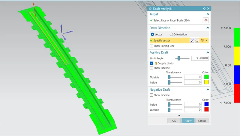
Draft Analysis:
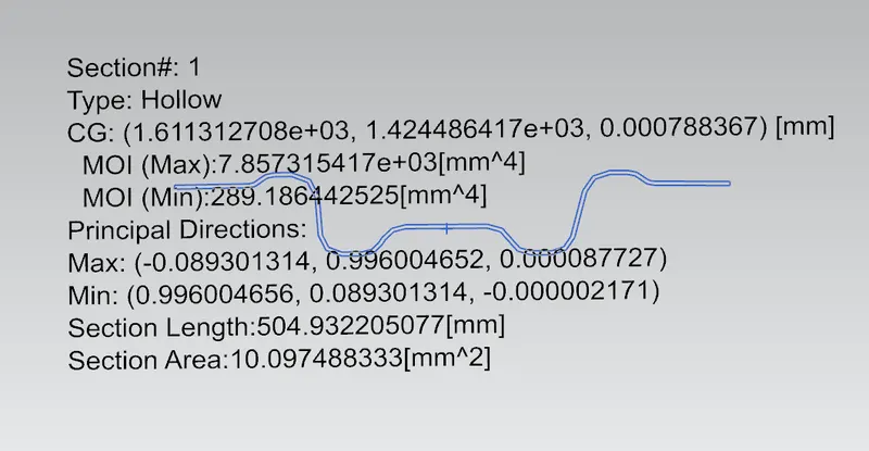
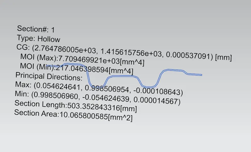
Section Inertia Analysis:
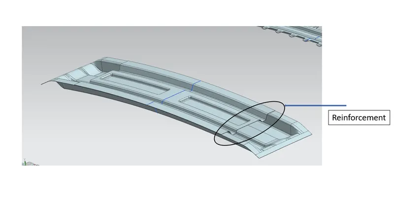
Center Roof Rail:
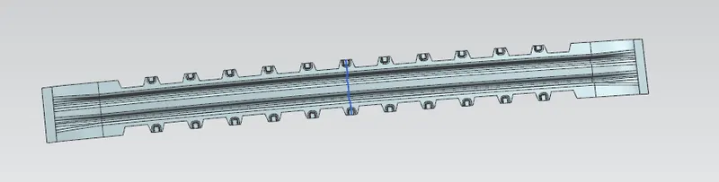
The center roof rail also has a reinforcement to give extra stiffness to the roof.
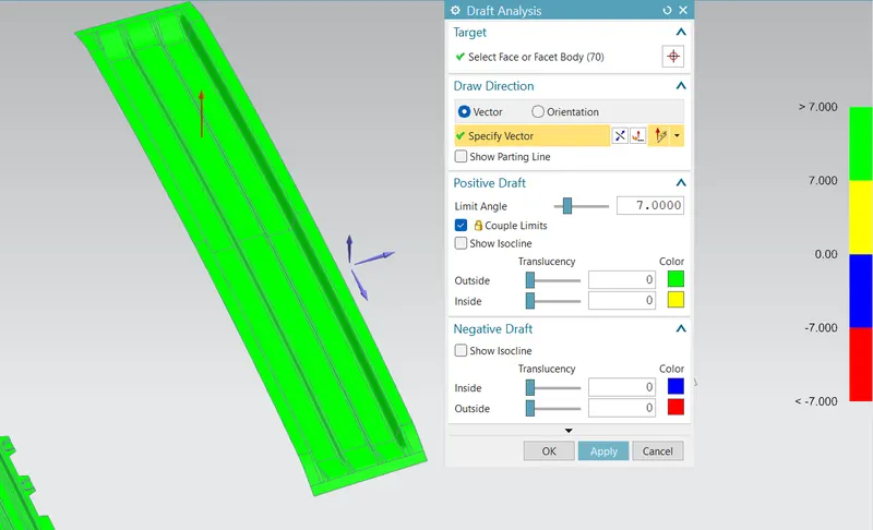
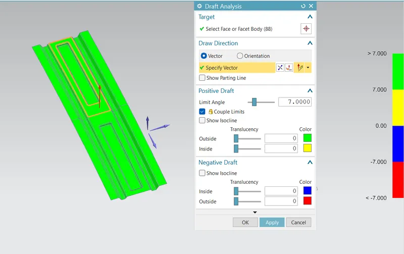
Draft analysis:
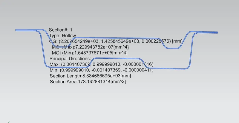
Section Inertia Analysis:
Bow Roof Rail - II:
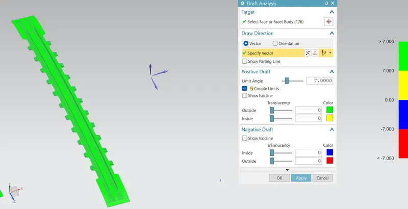
Draft Analysis:
Section Inertia Analysis:
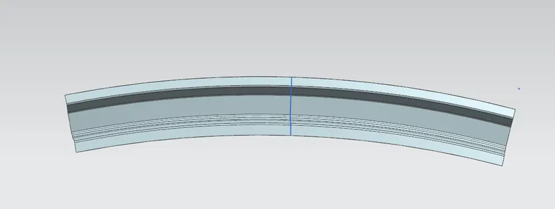
Rear Roof Rail:
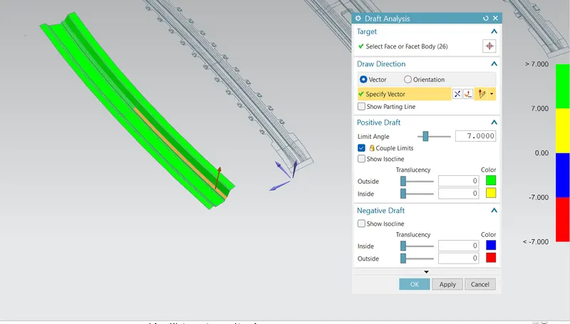
Draft Analysis:
Section Inertia Analysis:
Curvature Study:
Checking of heat Distortion Criteria:
W = [1.73 x 10^(-3) x L] + [1.85 x 10^(-8) x (R^2)/t] + [ 1.10x10^(-3) x l] - 2.68
Judgement Condition : OK< 2.7> 3.1
Where
L = Roof Length in X-Direction[mm](Roof dimension in 0-Y)
R = Roof curvature
R = 2(Rx*Ry)/(Rx+Ry)
Rx = X curvature
Ry = Y curvature
t = Roof plate thickness [mm]
l = Bow Roof Span [mm]

According to Heat distortion criteria, the design is meeting the needs in all the sections.
Checking of Snowed condition:
Qr = [Iy x t2] / [α x s x [(Rx + Ry)/2]2 x 10-8]
Where
α = My x Lx2 x 10-12 , My = Y(Ly-Y)
Judgement condition = Qr ≥ 3.1
250 ≤ s ≤ 380
t = Roof plate thickness [mm]
Ly = Distance between the front and rear roof Rails on the Vehicle along with 0Y[mm]
Length of Roof panel with the center point between Roof rail Front /Rear as the front and rear reference point.
Lx = Distance between the Left and Right end of the roof on the Roof BOW [mm]
The width of the roof panel is exposed on the surface.
Y = Distance front Front Roof Rail to Roof BOW[mm]
s = Distance for which Roof BOW bears divided load [mm]
s = L1/2 + L2/2
Iy = Geometrical moment of inertia of Roof BOW (Y cross-section )[mm4]
Rx = Lateral direction curvature radius of roof panel Y cross-section on Roof BOW [mm]
Roof panel curvature Radius of the Length Lx in Front view
Ry = Longitudinal Direction curvature radius of the Roof panel X cross-section on Roof BOW [mm]
Roof panel X curvature radius of length s in Side view

The curvature of the class A surface between the Center roof rail and bow roof rail II can be adjusted to improve the snowed condition in the location.
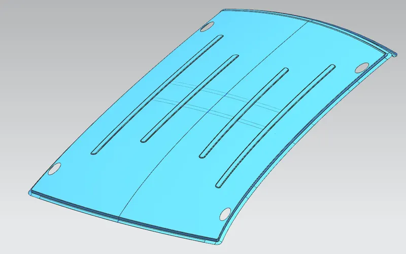
Embosses was Created on the roof to increase the roof strength and meet the conditions.
Draft analysis of roof outer panel:
Conclusion:
With the help of Surface inputs and master sections, Ditch areas and required flanges were created in the roof outer panel.
Front & rear roof rails, Bow roof rails, and center roof rails and reinforcements were designed. To check the manufacturing feasibility of these components, a draft analysis is done on the component with a limit value of 7 deg. All the components cleared draft analysis except flanges on the ditch area as it is given in the instructions that the draft angle for flanges is 3 deg.
From the Heat distortion study, the design satisfies all the needs and only the curvature can be increased in the CRR and Bow roof rail II region to meet snowed criteria. To neglect this embosses were created on the roof outer panel as this improves the strength of the roof.