Roof challenge
Roof Design
Aim: To design Automotive Roof from the given styling surface.
Introduction
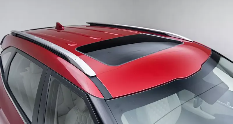
The automotive roof plays a crucial role in the aerodynamics and the internal strength of the vehicle. It is the upper part of the vehicle which starts from the A-pillar and goes to the D-pillar. It sits above the passenger compartment, protecting the vehicle occupants from sun, wind, rain, and other external elements. Other than protecting the passengers from the sun, rain etc. roofs play a major role in protecting the passengers from rollover accidents. The roof’s BIW influences the aftermath effects of crush load, Snow load & heat distortion criteria. Under the roof outer panel that is seen from the outside, there are many other structures under the roof that contribute to its strength and stability. The number of such reinforcement structures/supports differs with respect to the size of the vehicle. They are primarily installed on flatter areas of the roof to enhance strength.
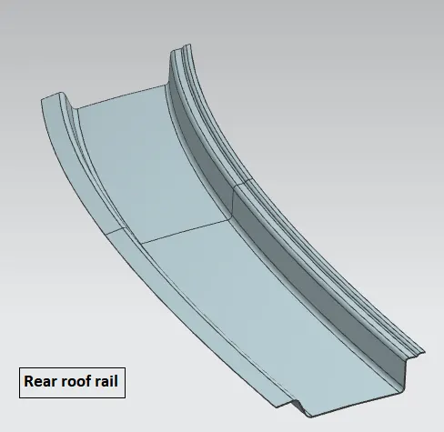
Reinforcements are classified as Front Roof Rail, Rear Roof Rail, Centre roof rail and Bow roofs, which are spot welded to roof flanges & ditch areas and improves NVH value by increasing the strength of the roof using mastic sealants.
Objective:
For the given Roof styling surface from the styling department,
- Develop the roof with essential flanges with appropriate ditch area and reinforcements as required.
- Provide appropriate dimensional parameters.
- Do a curvature study on the roof and perform calculations to determine the position of the bow-roof by appropriate criteria.
- Check for draft analysis with feasible tool opening angle, and find Sectional Inertia on the 0-Y section.
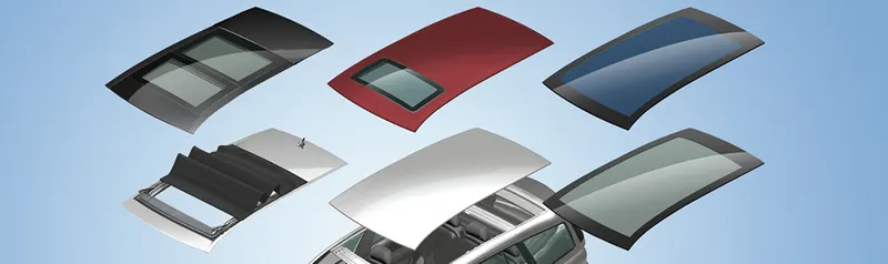
Types of roof:
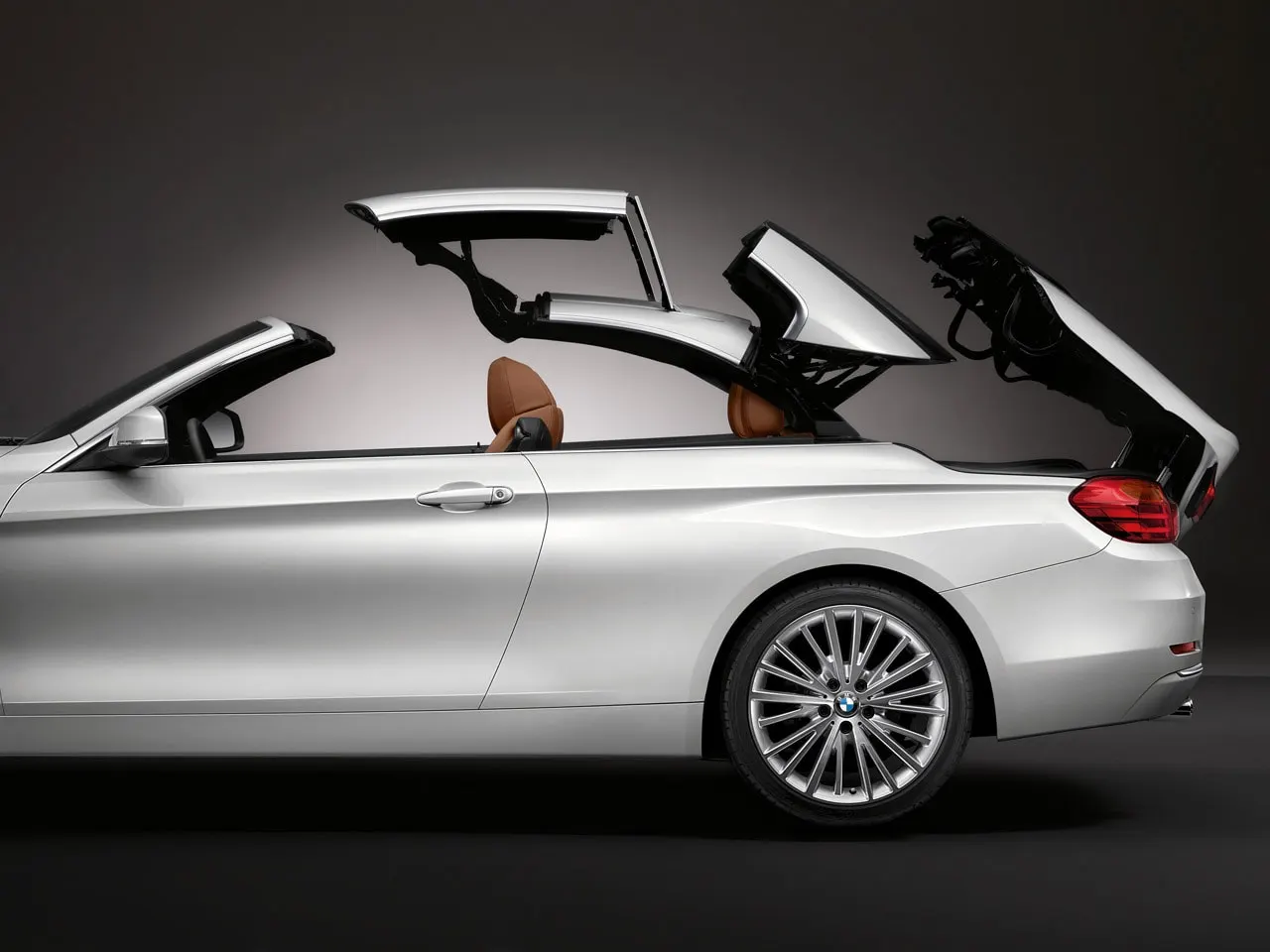
- Convertible roofs
The folded convertible top is called the stack. The methods of retracting and storing the roof vary between models. It allows an open-air driving experience, with the ability to provide a roof when required. Potential drawbacks of convertibles are reduced structural rigidity.
- Hardtops
It is the rigid form of automobile roof, which is typically manufactured from metal. A hardtop roof can be either fixed (i.e. not removable), detachable for separate storing or retractable within the vehicle itself.
- Sunroof/Moonroof
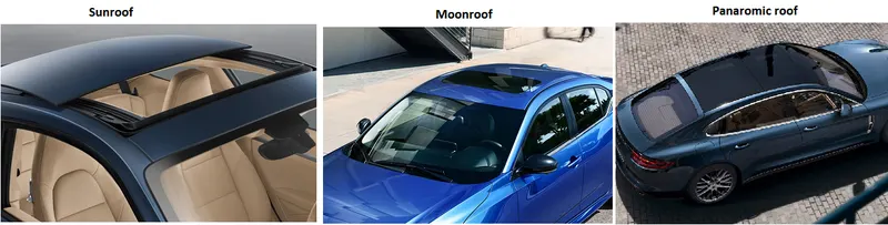
A sunroof is a movable panel that is operable to uncover another window in the roof of your vehicle, allowing light and/or fresh air into your car. It can be manually operated or motor-driven, and are available in many shapes, sizes and styles. While the moonroof is a stationary glass pane rigidly mounted in the roof panel over the passenger compartment. It has a glass panel that is transparent and usually tinted. Panoramic roofs usually slide open much further than the standard sunroof/moonroof and extend just above the front passengers to well behind the second row of seats.
- T-Tops
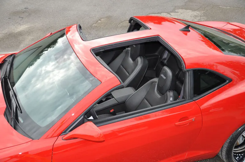
It is an automobile roof with a removable panel on each side of a rigid bar running from the center of one structural bar between pillars to the center of the next structural bar. The panels are usually made of auto-grade safety glass.
- Targa tops
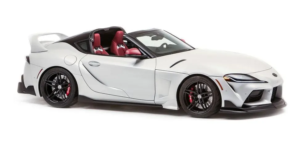
A Targa top is a type of semi-convertible car roof. It was originally designed to help race car drivers get in and out of the vehicle quickly, this car body style has a roll bar that runs behind the seats across the width of the car, with the roof section above the driver's head being removable.
- Vinyl roofs
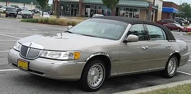
Vinyl roof refers to a vinyl covering for an automobile's top. This covering was originally designed to give the appearance of a convertible to models with a fixed roof, but eventually, it evolved into a styling statement in the 1970s.
Design Considerations:
- Visibility criteria
- Head Clearance
- Curvature study
- Heat distortion & Snow load criteria
- Safety Parameters
Components:
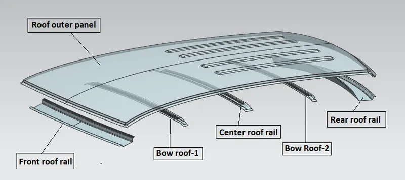
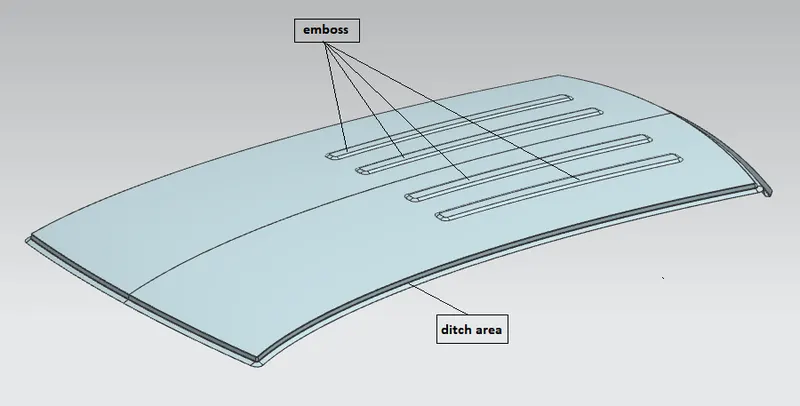
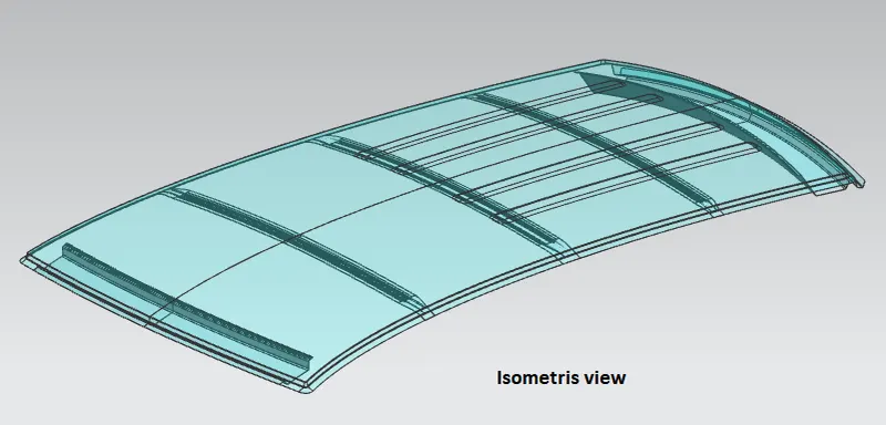
- Roof outer panel with necessary flanges and ditch area: It is the extended portion of the main roof which joined with other BIW panels. The various reinforcements (Roof rails & bow roofs) mentioned are joined to the ditch area with spot welds as those regions are not exposed. While the regions which are exposed and are needed to be joined with outer panels, mastic sealants are used thereby improving the NVH of the vehicle. While designing the ditch area, factors like headroom clearance, visibility criteria, clearance for windshield & backdoor etc are taken into consideration. Embosses are provided for improving the strength of the roof.
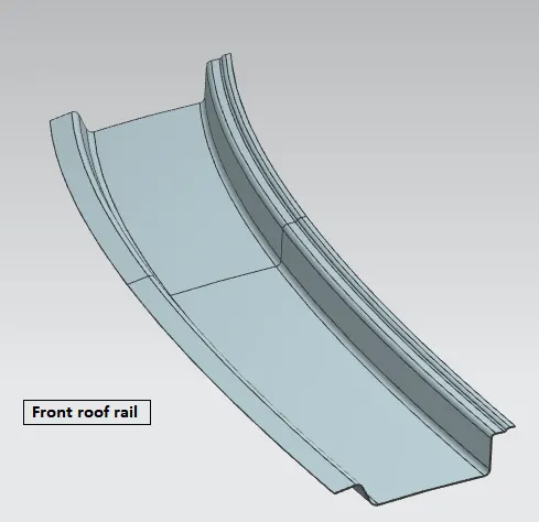
- Front roof rail:
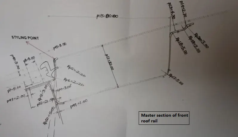
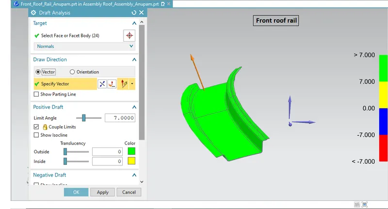
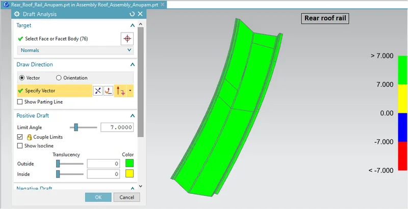
It is the supporting component that joins with windshield glass, bodyside outer and inner panels. It is usually made from body side outer scrap and usually has the same thickness as of body side outer. A draft angle of 7 degrees is provided keeping in mind the deep-drawing operation. The Visibility criteria and headroom clearance were taken into consideration for the lowermost flange. The region connecting the windshield and the roof were spot welded and the other end of the roof rail is joined with the roof using mastic sealants for increased strength thereby improving the NVH of the vehicle.
- Rear Roof rail:
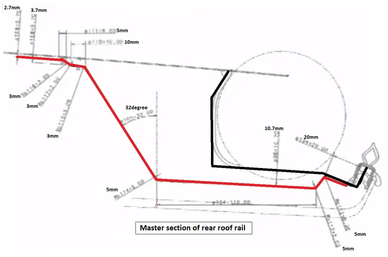
It is also the supporting component in the roof assembly which joins with the back door, bodyside outer and inner panels, same draft angle and thickness is used as in the front roof rail. While designing it, rear headroom clearance and rear visibility criteria are taken into consideration. Some key inputs are taken from the backdoor design to achieve the required clearance. Similar to front roof rail spot welds are applied in the region connecting with the backdoor portion and another end is joined using mastic sealants.
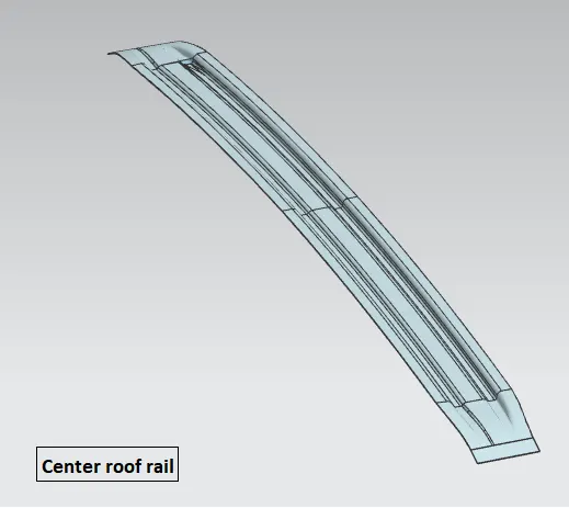
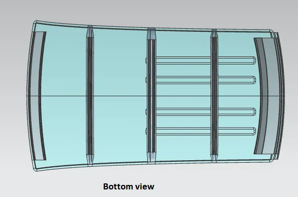
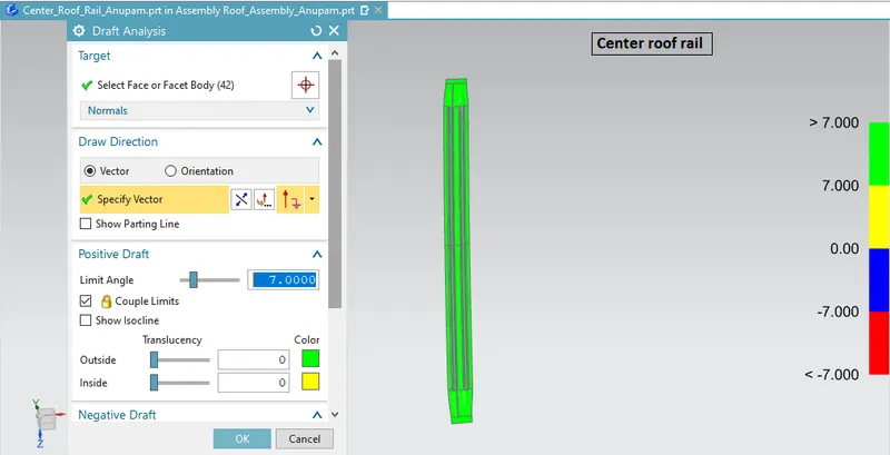
- Center Roof rail: Similar to other rail designs we have to take into consideration the headroom clearance, visibility criteria etc while designing the center roof rail. For additional strength, a bow roof can be placed along with it. Unlike the front and rear roof rails, spot welds are not applied for joining these rails to the roof, instead mastic sealants are introduced between them, since the Center roof rail and /or bow roofs are fully positioned under the styling surface of the roof. A maximum gap of 5mm is maintained for mastic sealant application.
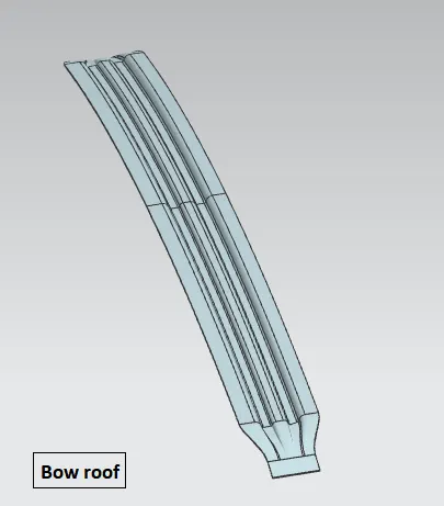
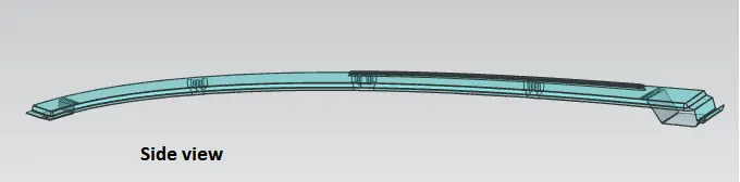
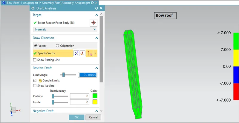
- BOW roofs: It is the additional stiffening component used in the roof assembly for the localised strength improvement, mostly on flatter regions of the roof. No.of bow roofs provided depends upon the overall dimensions of the roof. More flatter and longer the roof more bow roofs are provided. Since it joins directly with the roof outer panel, mastic sealants are used. Usually, each mastic point is said to have around 80mm circular effective area and a maximum of 5mm gap is maintained between the surfaces where mastic is to be applied. The position of the roofs is determined on the basis of heat distortion criteria & Snow load criteria. End flanges of the bow roofs are joined with the roof ditch portion by spot welding. Various bow roofs used in assembly are similar in dimension, their curvature profile will vary depending upon the positions they are placed in.
Assembly: In this assembly Top down approach was followed wherein from given styling surface the outer panel was created using various tools/commands in NX. After that others parts were modelled as per the requirements one by one.
Analysis:
Draft Analysis:
Every part which is manufactured from press tool or other forming tools require some positive draft on the faces which are parallel to the tooling direction. If we don’t give draft (Zero Draft) or give negative drafts on these faces it will stick to the mould surface and when the mould is in motion it will destroy surface thus reducing its surface finish. Thus Draft Analysis command enables us to detect if the part we have drafted can be easily ejected or not. It also give insights about the critical zones, so that appropriate changes in the design can be made if needed.
Section Modulus:
The section modulus of the cross-sectional shape is of significant importance in designing beams or flexural members. It is a geometric property which is of direct measure of the strength of the beam. A beam that has a larger section modulus than another will be stronger (i.e more resistive to bending) and capable of supporting greater loads.
The elastic section modulus (S) is defined as the ratio of the overall second moment of area (I) (or area moment of inertia) to the most extreme fiber distance (y) from the overall bending neutral axis of a part or beam system.
`S = I/y`
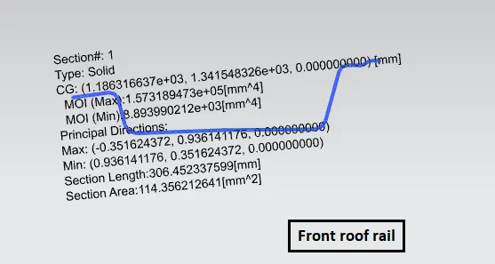
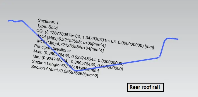
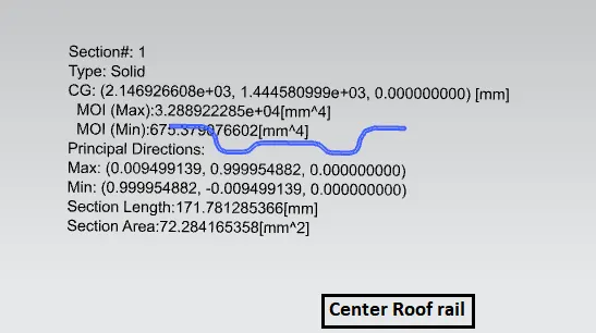
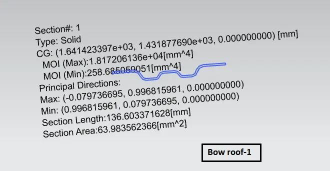
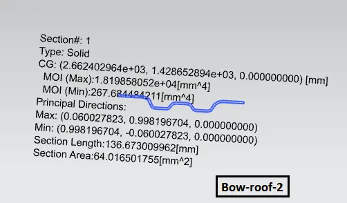
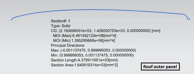
Section Moduli of various roof rails are as follows:
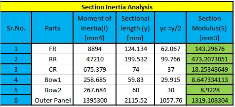
Note: Section modulus can be improved by modifying cross-sectional design within permissible limits.
Curvature study: It is done to justify the positioning of the Bow roofs. There are mainly three criteria to fulfill.
- Heat Distortion criteria
- Snow Load criteria
- Roof crush test
(Note : Roof Crush testing is done only after the part is manufactured.)
Heat Distortion Analysis
`W=1.73xx10^-3L+1.85xx10^-8xxR^2/t+1.1xx10^-3xxl-2.68`
Judgement condition: `W<2.7`
where,
L- Length of the roof in X-direction(mm) (Roof dimension along 0-Y)
`R=2((Rx xxRy)/(Rx+Ry))`
R- Roof curvature
Rx - X curvature
Ry - Y curvature
t- Roof sheet thickness(mm)
`l`- Bow Roof span (mm)
Procedure:
- From the 0-Y axis, at around -3Y distance (300mm) a line is drawn parallel to it on the top plane. Then that line was offsetted by 100mm on either side of -3Y line. The Centerlines of each roof rail was determined and necessary intersection points were marked in the sketch.
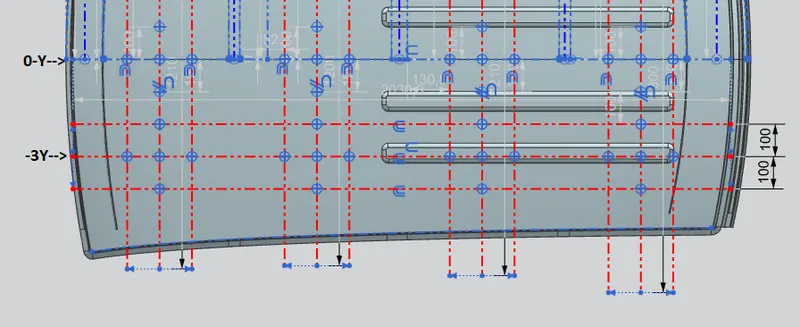
- The intersection points were projected on the roof surface and appropriate points were joined by using 3 point arcs to find Rx & Ry value in each case.
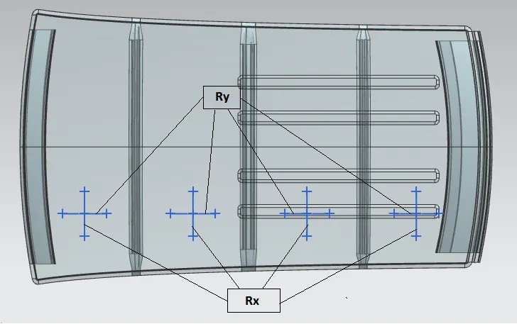

Thus, all values of W<2.7. So according to Heat Distortion criteria current positioning of all the Roof rails and Bow roofs are found to be within permissible limits.
Snow Load Analysis:
`Qr=(Iyxxt^2)/(alphaxxs((Rx+Ry)/2)^2xx10^-8`
Judgement condition: `Qr >=3.1`
where,
`alpha=MyxxL x^2xx10^-12`
`My=Y(Ly-Y)`
`250<=s<=380`
`t=`Roof plate thickness(mm)
`Ly=`Distance between the front and rear roof rails on the vehicle along 0-Y (mm). Length of the roof panel with centre point between roof rail front/rear as the front and rear reference point.
`Lx=`distance between the left and right end of the roof on the roof BOW (mm). Width of the roof panel exposed.
`Y=`Distance from front roof rail to roof BOW (mm)
`s=`Distance for which roof BOW bears divided load (mm) `s=(L1)/2+(L2)/2`
`Iy=`Geometrical moment of inertia of roof BOW (Y cross-section) `(mm^4)`
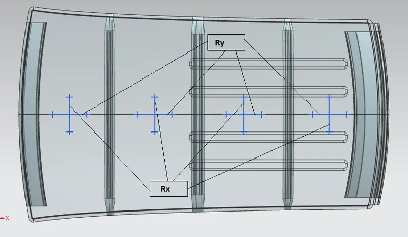
`Rx=`Lateral direction curvature radius of the roof panel Y cross-section on roof BOW (mm). Roof panel curvature radius of length `Lx` in front view
`Ry=`Longitudinal direction curvature radius of the roof panel X cross-section on roof BOW (mm). Roof panel X curvature radius of length `s` in side view
Procedure:
- Draw 2 lines offsetted by 100mm to 0-Y line on either sides. The Centerlines of each roof rail was determined and necessary intersection points were marked in the sketch.
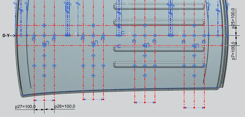
- The intersection points were projected on the roof surface and appropriate points were joined by using 3 point arcs to find Rx & Ry value in each case.
Results:
- All the parts successfully cleared draft analysis
- The proposed Roof design has successfully cleared heat distortion analysis.
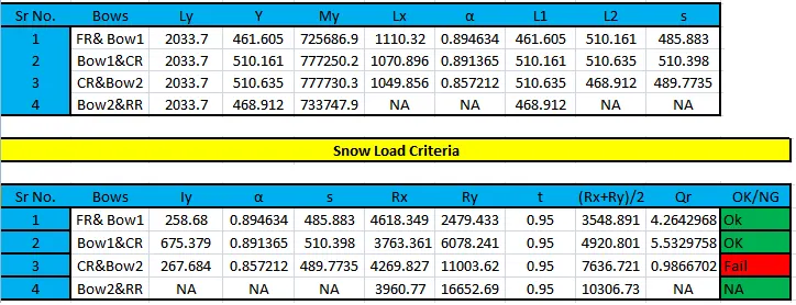
- The portion between Center roof rail and bow roof 2 failed in Snow load analysis.
- Embosses where designed in the region where roof failed in Snow load analysis thereby increasing its local strength.
Conclusion: The roof was successfully designed considering all the design parameters and various criteria. Also it successfully cleared various analysis done on it.