Radar Mast & Final Assembly of Yacht
Modelling of Sunseeker Predator Yacht
Objective:
- To model different parts of Yacht using various Surfacing tools in Solidworks
- To assemble different parts modeled of Yacht.
Introduction:
Part Modelling / Solid Modeling
- PART modeling basically means to create a virtual prototype of an object which can be used for different purposes.
- Solid modeling is for representing solid objects in the areas of CAD, engineering analysis, graphics and animation as well as prototyping and product visualization. It uses mathematical principles to create 3D solid objects.
- Solid models can intersect, join and subtract objects from one another to create the desired results as far as shape and form.
- Solid models are parametric i.e if you modify any one of the features in the part, subsequent features get modified accordingly based on the relations given.
- Propeller, Radar, Garage Door, Middle Seat, Radarmast are modelled using part modeling.
Surface Modeling:
- Surface modeling focuses more on the external aspects of an object. It develops an object by stretching a surface over it with the help of 3D curves. It is essentially describing the surface boundaries of the object
- This type of modeling is used for creating the external aesthetics of a product or design. It can allow for more free-form shape. While using surface modeling, it can be hard to go back and make changes because they are not parametric. Making changes in one area may not create updates in the whole design
- Hull, Front Seat, Rear Seat & Superstructure are modelled using Surface modelling.
Design Methodology:
Bottom-up Design
Bottom-up design is the traditional method. You first design and model parts, then insert them into an assembly and use mates to position the parts. To change the parts, you must edit them individually. These changes are then seen in the assembly.
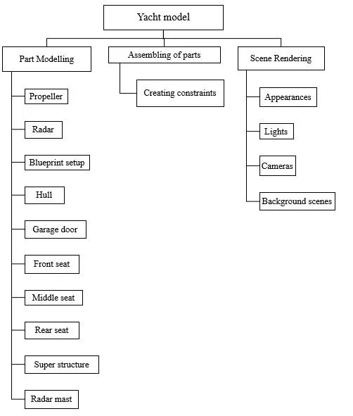
Parts Modeled for Yacht Assembly
The following parts of Chopper are modelled in Solidworks and assembled together:-
- Propeller
- Radar
- Blueprint
- Hull
- Garage Door
- Front Seat
- Middle Seat
- Rear Seat
- Superstructure
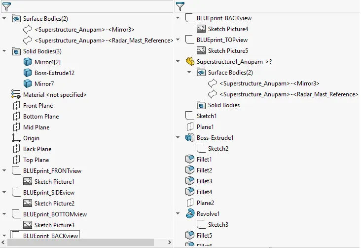
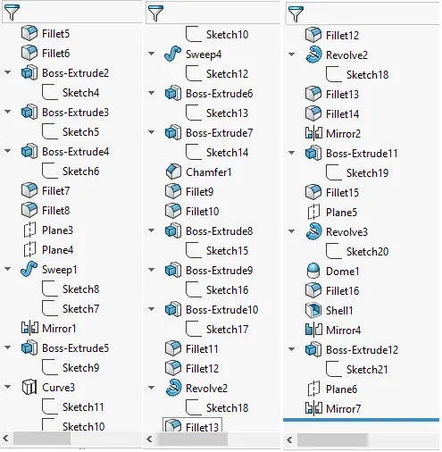
- Radar Mast
Let us see the tools/features used to model each part
- Propeller
A propeller is a part with a rotating hub and radiating blades that are set at a pitch to form a helical spiral, that, when rotated, exerts linear thrust upon a working fluid, such as water or air.
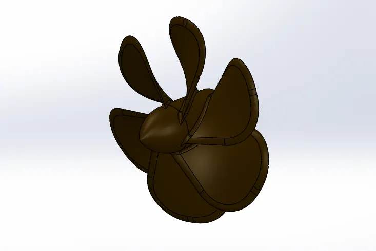
Features used to model Propeller
- Sketch
- Revolve boss/ base
- Plane
- Loft
- Fillet
- Extrude cut
- Circular Pattern
- Appearances
Sketch
The first thing we do is create a Sketch, when we open a new part file. The sketch is the basis for a 3D model. We can create a sketch on any of the default planes (Front Plane, Top Plane, and Right Plane), or a user created plane. We can start by selecting Sketch Entity tools (like line circle…and so on), Sketch Tool, Planes, Extrude boss/base or Revolve boss/base or any other surface on already made model.
Revolve boss/ base
Revolved section is obtained when we rotate the sketch around any particular axis, centreline, sketch line or linear edge.
Plane
We can create planes in part or assembly documents. We can use planes to sketch, to create a section view of a model, for a neutral plane in a draft feature, and so on.
Loft
The loft feature allows you generate complex geometry in a single feature by interpolating surfaces between various cross-sections of a model. These cross-sections can be sketches, faces, or edges. In the loft interface, these cross-sections are considered “Loft Profiles”.
Fillet
Fillet/Round creates a rounded internal or external face on the part. You can fillet all edges of a face, selected sets of faces, selected edges, or edge loops.
Extrude cut
It is a handy feature which helps in material removal of a 3D model using 2D sketches. It is exactly opposite of Extrude boos/base feature, while we can cut in both directions it is used mostly for creating holes channels, slot etc.
Circular Pattern
It is used for repeating the same entities again and again. Its types include Linear Pattern, Circular pattern, Curve Driven Pattern, Sketch Driven Pattern, Table driven Pattern, Fill Pattern, Variable Pattern. Circular patterns are used to create multiple instances of one or more features that we can space uniformly around an axis.
Appearances
An appearance defines the visual properties of a model, including color and texture. Appearances do not affect physical properties, which are defined by materials. Every material is assigned a default appearance that emulates the look of the material.
- Radar
Marine radars are X band or S band radars on ships, used to detect other ships and land obstacles, to provide bearing and distance for collision avoidance and navigation at sea.
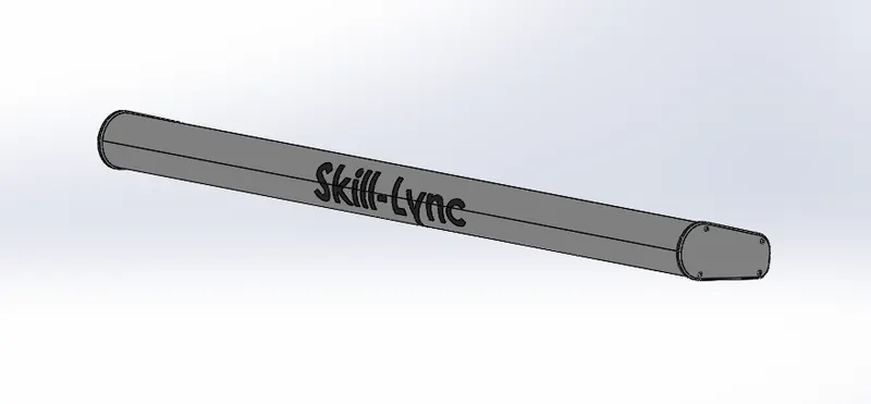
Features used to model Radar
- Sketch
- Extrude boss/base
- Fillet
- Extrude cut
- Sketch Pattern
- Mirror
- Split
- Appearances
Extrude boss/base
We can extrude base features and other features using Extrude (2D to 3D toolbar) with partial closed sketches.
Sketch Pattern
Using sketch points within a sketch, we can specify a feature pattern. The seed feature propagates throughout the pattern to each point in the sketch. We can use sketch driven patterns for holes or other feature instances.
Mirror
It is used to create exact replica of the features, faces and /or bodies about a face or plane
Split
Split Line feature is used to create multiple parts from an existing part. We can split one or more solid or surface bodies by projecting an entity (Sketch, solid, surface, face, plane or Spline) on other surfaces or curved/planar surfaces. To split a surface, the Trimming Surface must extend past the boundaries of the surface to split.
- Blueprint
It is a guide for making the model, it’s a design or pattern that can be followed.
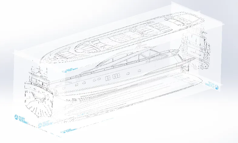
- Hull
A hull is the watertight body of a ship, boat, or flying boat. The hull may open at the top or it may be fully or partially covered with a deck. Atop the deck may be a deckhouse and other superstructures.
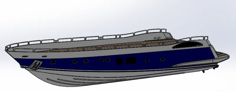
Features used to model Hull
- Sketch
- Projected Curve
- Surface Loft
- Surface trim
- Surface Extrude
- Surface knit
- Surface fill
- Shell
- Extrude Boss
- Extrude Cut
- Fillet
- Chamfer
- Plane
- Sweep
- Dome
- Linear Pattern
- Helix/Spiral
- Delete face
- Split
- Offset Surface
- Mirror
- Decals
- Appearances
Projected Curve
It is a tool used to form 3D curves from two 2D curves from two different planes.
Surface Loft
Loft Surfaces are surfaces generated by multiple 3D Curves or existing edges creating a smooth tangency between the selected curves.
Surface trim
We can use a surface, plane, or sketch as a trim tool to trim intersecting surfaces. We can also use a surface in conjunction with additional surfaces, as mutual trim tools. Trim surface includes the following modes: Standard & Mutual
Surface Extrude
We can extrude the boundary edges of a face of a solid body or edges of a surface body in a customized direction
Surface knit
Use the Knit Surface tool to combine two or more faces and surfaces into one.
Surface fill
The Filled Surface feature constructs a surface patch with any number of sides, within a boundary defined by existing model edges, sketches, or curves, including composite curves. This feature is mostly used to construct a surface to fill a gap in a model.
Shell
It hollows out a part, leaves open the faces you select, and creates thin-walled features on the remaining faces. If you do not select any face on the model, you can shell a solid part, creating a closed, hollow model. You can also shell a model using multiple thicknesses.
Chamfer
The chamfer tool creates a bevelled feature on selected edges, faces, or a vertex.
Sweep
sweep is a tool that creates a solid, a cut or a surface feature by moving a profile along a path.
Dome
It is used to create a bulgy profile on a surface. Domes can be applied to faces whose centroid lies outside the face. This allows us to apply domes to irregularly shaped contours.
Linear Pattern
We can use linear patterns to create multiple instances of one or more features that you can space uniformly along one or two linear paths.
Helix/Spiral
You can create a helix or spiral curve in a part.
Delete face
We can delete faces from surface and solid bodies.
Offset Surface
The Offset Surface tool creates a new surface body from an existing set of faces. The faces may be solid or surface faces.
Decals
A decal is a 2D image applied to a model. You can use decals to apply warning or instruction labels to models. You can use decals to create model details that you can represent with an image instead of with the model geometry, such as a car grill or a picture frame. You can view and apply decals in SOLIDWORKS. You can view decals in eDrawings and PhotoView 360
- Garage Door
It is used to close the garage part in Hull.
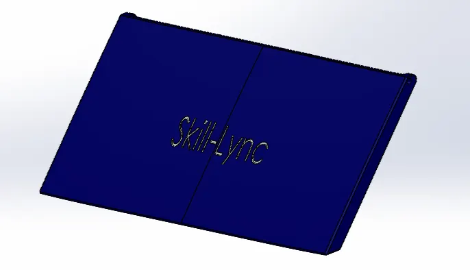
Features used to model Garage
- Sketch
- Extrude Cut
- Shell
- Fillet
- Mirror
- Plane
- Text
- Appearances
Text
Sketches text on any set of continuous curves or edges (including circles or profiles made up of lines, arcs, or splines on the face of a part) and extrude or cut the text.
- Front Seat
Front seat is Located in the front portion of the Hull
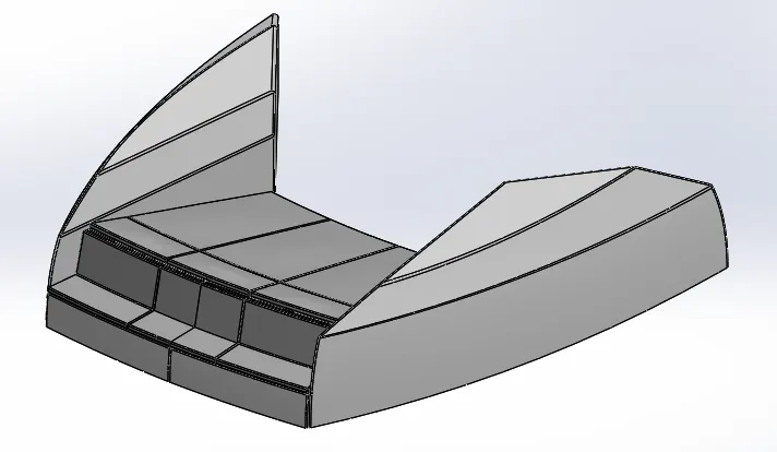
Features used to model Front Seat
- Sketch
- Plane
- Surface Sweep
- Surface Extrude
- Surface Trim
- Surface Fill
- Surface Loft
- Surface Knit
- Chamfer
- Revolve boss
- Extrude Cut
- Fillet
- Mirror
- Dome
- Appearances
Surface Sweep
Sweep Surfaces are surfaces that are generated from a section curve positioned along a path.
- Middle Seat
As the name suggests it is situated on the middle portion of the Hull under superstructure
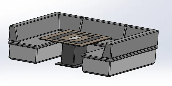
Features used to model Middle Seat
- Sketch
- Extrude Boss
- Plane
- Chamfer
- Fillet
- Mirror
- Extrude Cut
- Appearances
- Rear Seat
It is present on the rear part of the hull
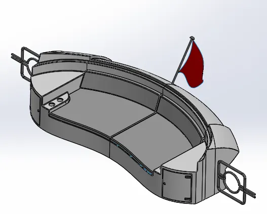
Features used to model Rear Seat
- Plane
- Sketch
- Surface Sweep
- Surface Offset
- Surface Trim
- Ruled Surface
- Surface Knit
- Surface Extend
- Surface Extrude
- Surface Loft
- Extrude Boss
- Extrude Cut
- Chamfer
- Fillet
- Sweep
- Mirror
- Revolve Boss
- Appearances
Surface Offset
The Offset Surface tool creates a new surface body from an existing set of faces. The faces may be solid or surface faces.
Ruled Surface
The Ruled Surface command creates surfaces that extend out in a specified direction from selected edges.
Surface Extend
We can extend a surface by selecting an edge, multiple edges, or a face.
- Superstructure
It means to add a construction to an already existing structure. In ships this is the name given to the part of the ship that emerges from the deck They are designed in a manner, so that, they add value and hinder the speed and mobility in the least. The superstructure is mostly designed in fashion because it is the most easily visible part of the ship, in fact it is the identification of the ship.
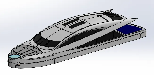
Features used to model Superstructure
- Sketch
- Surface Extrude
- Plane
- Surface Sweep
- Surface Knit
- Fillet
- Ruled Surface
- Surface Trim
- Projected Curve
- Surface Loft
- Surface Fill
- Surface Extend
- Extrude Boss
- Extrude Cut
- Delete Face
- Thicken
- Dome
- Sweep
- Split
- Mirror
- Offset Surface
- Chamfer
- Appearances
Thicken
Creates a solid feature by thickening one or more adjacent surfaces.
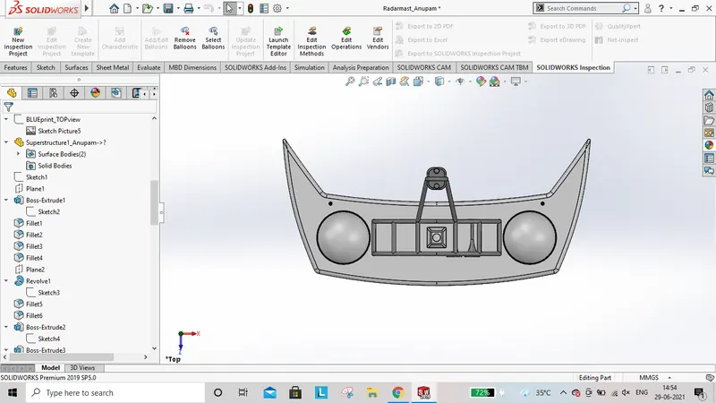
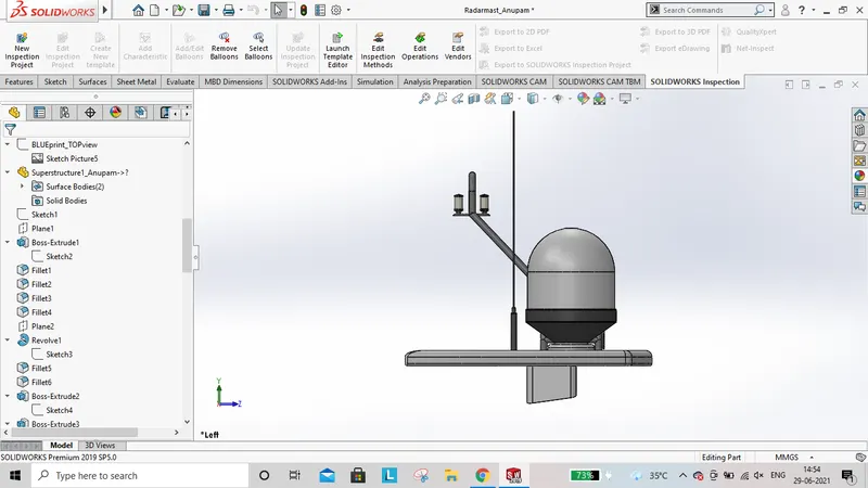
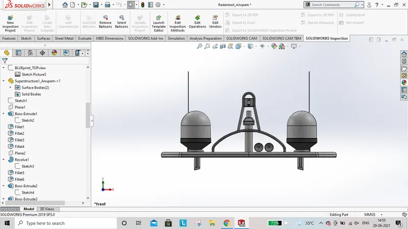
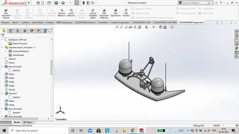
- Radar Mast
It is the part on which Radar is Placed.
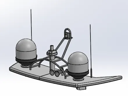
Features used to model Radar Mast
- Sketch
- Plane
- Extrude Boss
- Fillet
- Revolve boss
- Sweep
- Mirror
- Project Curve
- Chamfer
- Dome
- Shell
- Appearances
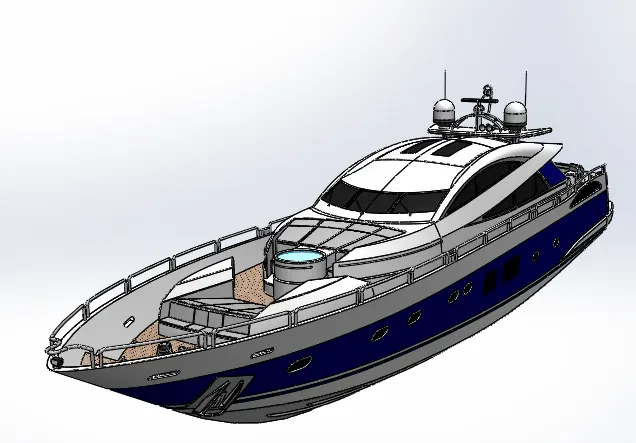
Assembly of Yatch
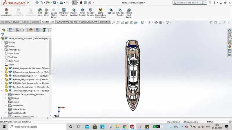
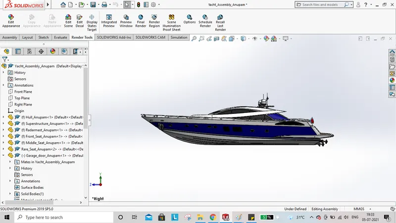
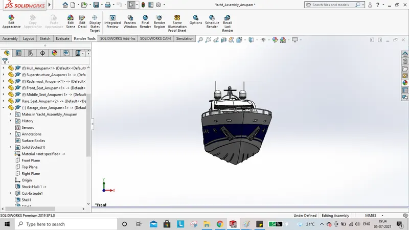
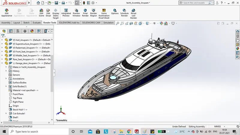
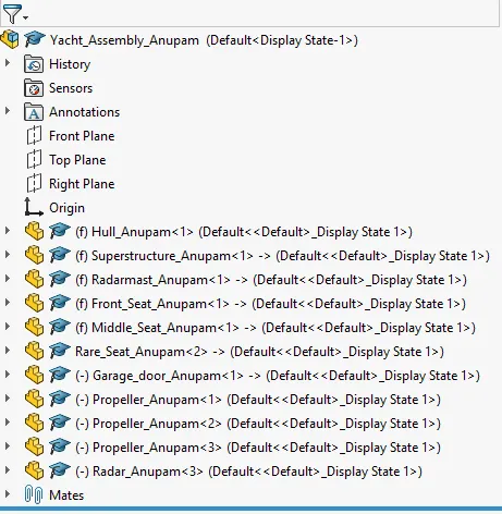
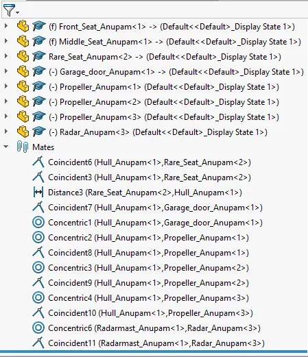
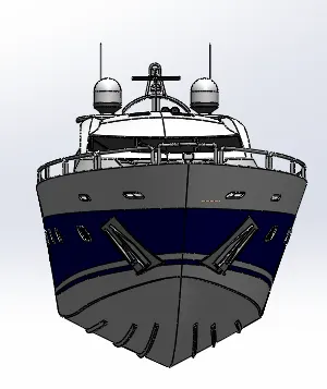
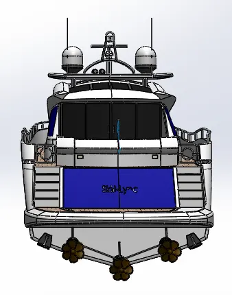
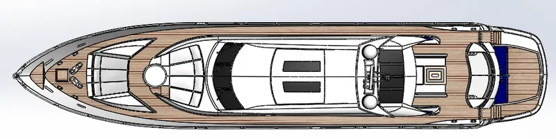
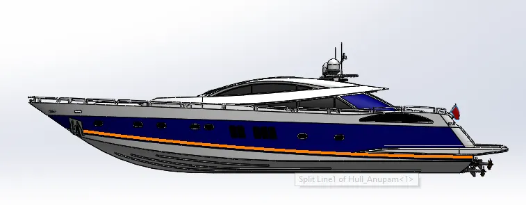
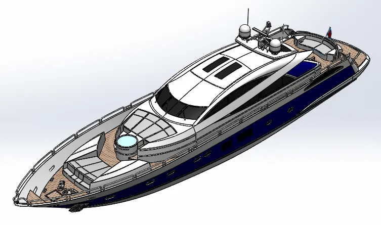
Firstly, the Hull component is inserted in the assembly by using insert part option and it is given appropriate mates with respect to assembly planes. After that all other parts of Yacht are inserted one by one and proper mates are given.
Conclusion
- The various parts of the Yacht are sketched & modelled individually in Solidworks
- The above parts modelled are inserted into assembly environment and after applying proper mates they are assembled together.