Advanced Sheet Metal Design Using NX Cad Challenge_6_Bracket
Bracket DESIGN
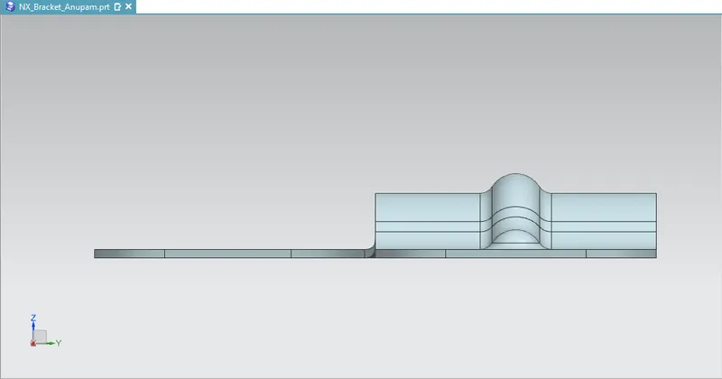
Objective: To design Bracket from given 2D drawing and create draft of it using Siemen’s NX Sheet Metal application
Introduction:
Sheet metal is metal formed by an industrial process into thin, flat pieces. Sheet metal is one of the fundamental forms used in metalworking, and it can be cut and bent into a variety of shapes. Countless everyday objects are fabricated from sheet metal. Thicknesses can vary significantly; extremely thin sheets are considered foil or leaf, and pieces thicker than 6 mm (0.25 in) are considered plate steel or structural steel. Sheet metal is available in flat pieces or coiled strips. The coils are formed by running a continuous sheet of metal through a roll slitter.
Sheetmetal is one of the many workbenches available in Siemens’s NX CAD Software.NX Sheet Metal provides a set of tools within the NX design environment that allows for simple and fast design of sheet metal parts, dependent on their material and manufacturing process. With NX Sheet Metal, formed and unformed representations of the parts are created closely following the industry workflows and best practices for bending calculations, tooling, and sheet metal features. The value lies in improving quality and reducing cost of sheet metal parts by producing an accurate sheet metal pattern as the correct input for part manufacture.
NX sheet metal design software includes material and process information in sheet metal-specific modeling features: bends, flanges, tabs, cutouts, beads, dimples, louvers, corner and edge treatments, patterns and other formable features. You can also quickly convert solid models to sheet metal components, and create sheet metal parts that enclose other components.With NX sheet metal CAD tools, you can apply standard values, such as material thicknesses and bend radii, based on industry or company best practices. With folding and unfolding capabilities, you can work with models at any stage of the fabrication process. NX sheet metal software creates accurate flat patterns for documentation and manufacturing.
Design Methodology :
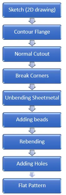
Tools/Features used: -
- Datum Coordinate System
With the introduction of parametric and geometric features, we needed some additional tools apart from other coordinate systems to define the intended location and orientation of objects as well as how they could be controlled. With a Datum CSYS, objects are created relative to some aspect of the datum object, such as a Point, Plane, or Axis.
The Datum CSYS contains 3 datum planes and 3 datum axes along with a coordinate system.When the Datum CSYS is moved, anything that referenced it will move as well.
- Sketch
In NX we can create the sketch of a feature by using two methods namely
- Direct Sketch (Sketch)
In direct Sketch, we can create sketch in the modelling environment directly by invoking the sketch tools available in the direct sketch group
- Sketch in task environment
In this method, we need to invoke the sketching environment by choosing the Sketch in task Environment tool from Menu --> Insert --> Sketch in task environment
We can create a sketch in NX by using the datum co-ordinate system (XC-YC, YC-ZC, or XC-ZC) or any reference plane.
- Contour Flange
It creates a base feature by extruding a sketch along a vector or adds material by sweeping a sketch along an edge or chain of edges. Contour flanges are flanges with several contours by extruding a profile that represents its cross-section. They can be used as a base feature or a feature added to a sheet metal part. Contour flanges can contain one or more bends at any angle
- Normal Cutout
It cuts material by projecting a sketch onto the model and then cutting perpendicular to the faces intersected by the projection. Planar sketches or 3D curves can be used to specify the section for the normal cut-out. A particular target body can be specified for normal cutout if the sheet metal is multibody
- Break Corner
It rounds or chamfers a sharp corner of a tab or flange.
- Unbend
Flattens a bend and the material adjacent to the bend.
- Bead
It lifts along the contour of a sketch that stimulates a stamping tool. It is like a raised rib in the sheet metal panel. It requires that you have at least one sheet metal panel in the active part as well as open or closed loop sketch.
- Rebend
It restores an unbend feature to its previous state, along with any features added after the unbend feature
- Hole
It adds a hole to one or more solid bodies in a part or assembly with options for counterbored, countersunk and threaded.
- Flat Pattern
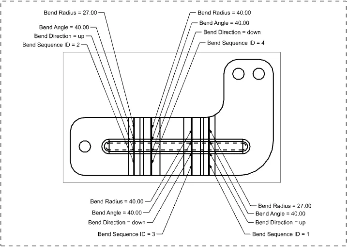
It creates a flat pattern feature from the formed sheet metals part. It creates a 2D representation of a 3D sheet metal part. We can include annotations for bending , punching or cutting manufacturing instructions.
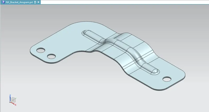
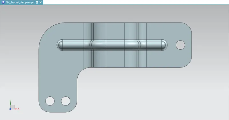
1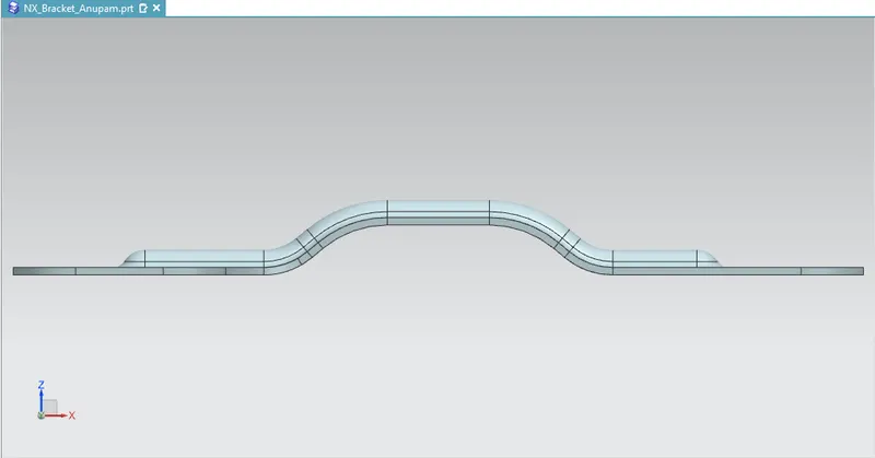
Conclusion :
The Bracket Design was completed with the help of given 2D drawing using tools like Contour Flange, Unbend, Hole, Bead, Break corner, Normal Cutout, Rebend, Flat pattern etc.