Photo Realistic Rendering
Modeling & Rendering of American Chopper using Solidworks
Objective:
- To model different parts of Chopper using various tools in Solidworks.
- To assemble different parts modeled of Chopper.
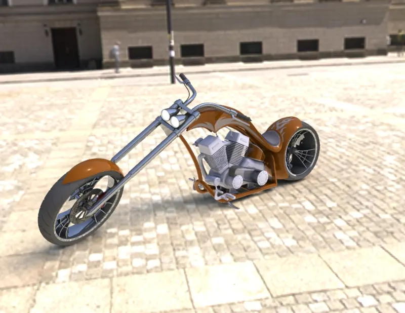
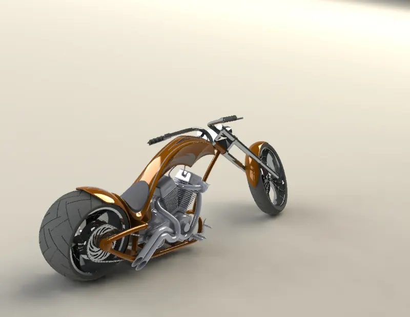
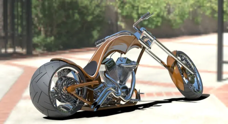
- To create Photorealistic model of the chopper and render the same using Photoview 360 or Solidworks visualize.
Introduction:
Part Modelling / Solid Modeling
- PART modeling basically means to create a virtual prototype of an object which can be used for different purposes.
- Solid modeling is for representing solid objects in the areas of CAD, engineering analysis, graphics and animation as well as prototyping and product visualization.
- It uses mathematical principles to create 3D solid objects.
- Solid models can intersect, join and subtract objects from one another to create the desired results as far as shape and form.
- Solid models are parametric i.e if you modify any one of the features in the part, subsequent features get modified accordingly based on the relations given.
- Transmission Belt, Kick Stand, Front Fender, Rear Fender, Oil Tank, Chain, Pedal, Front & Rear Wheels, Front fork, Chassis, and Engine are modelled using part modeling
Surface Modeling:
- Surface modeling focuses more on the external aspects of an object. It develops an object by stretching a surface over it with the help of 3D curves. It is essentially describing the surface boundaries of the object
- This type of modeling is used for creating the external aesthetics of a product or design. It can allow for a more free-form shape.
- While using surface modeling, it can be hard to go back and make changes because they are not parametric. Making changes in one area may not create updates in the whole design
- Surface modeling is used while modeling Fuel Tank
Design Methodology:
Bottom-up Design
Bottom-up design is the traditional method. You first design and model parts, then insert them into an assembly and use mates to position the parts. To change the parts, you must edit them individually. These changes are then seen in the assembly.
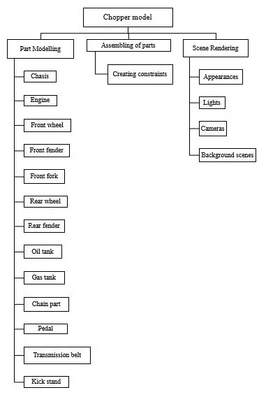
Parts Modeled for chopper Assembly
The following parts of Chopper are modelled in Solidworks and assembled together: -
- Transmission Belt
- Kick Stand
- Front Fender
- Rear Fender
- Chain
- Oil Tank
- Pedal
- Front Wheel
- Rear Wheel
- Front fork
- Chassis
- Engine
- Fuel Tank
Let us see the tools/features used to model each part
- Transmission Belt
The function of the Transmission Belt in the chopper is to transmit power from the Engine to Gear Box.
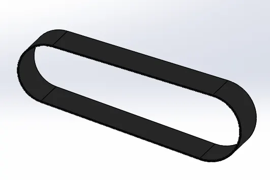
Features used to model Transmission Belt
- Sketch
- Offset
- Extrude boss /base
- Fillet
- Appearances
Sketch
The first thing we do is create a Sketch when we open a new part file. The sketch is the basis for a 3D model. We can create a sketch on any of the default planes (Front Plane, Top Plane, and Right Plane), or a user-created plane. We can start by selecting Sketch Entity tools (like line circle…and so on), Sketch Tool, Planes, extrude boss/base or Revolve boss/base or any other surface on an already made model.
Offset
Offset one or more sketch entities, selected model edges, or model faces by a specified distance. For example, you can offset sketch entities such as splines or arcs, sets of model edges, loops, and so on. You can offset finite lines, arcs, and splines. You cannot offset fit splines, previously offset splines, or entities that would result in self-intersecting geometry.
Extrude boss /base
We can extrude base features and other features using Extrude (2D to 3D toolbar) with partially closed sketches.
Fillet
Fillet/Round creates a rounded internal or external face on the part. You can fillet all edges of a face, selected sets of faces, selected edges, or edge loops.
Appearances
An appearance defines the visual properties of a model, including colour and texture. Appearances do not affect physical properties, which are defined by materials. Every material is assigned a default appearance that emulates the look of the material.
- Kick Stand
Its function is to hold the chopper in a vertical position when stationary.
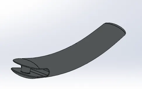
Features used to model Kick Stand
- Sketch
- Loft
- Dome
- Extrude boss /base
- Extrude Cut
- Split
- Fillet
- Appearances
Loft
The loft feature allows you generate complex geometry in a single feature by interpolating surfaces between various cross-sections of a model. These cross-sections can be sketches, faces, or edges. In the loft interface, these cross-sections are considered “Loft Profiles”.
Dome
It is used to create a bulgy profile on a surface. Domes can be applied to faces whose centroid lies outside the face. This allows us to apply domes to irregularly shaped contours.
Extrude Cut
It is a handy feature which helps in the material removal of a 3D model using 2D sketches. It is exactly the opposite of Extrude boss/base feature, while we can cut in both directions it is used mostly for creating holes channels, slots etc.
Split
The split Line feature is used to create multiple parts from an existing part. We can split one or more solid or surface bodies by projecting an entity (Sketch, solid, surface, face, plane or Spline) on other surfaces or curved/planar surfaces. To split a surface, the Trimming Surface must extend past the boundaries of the surface to split.
- Front Fender
It is mounted above the front wheel to protect the rider and other parts of the chopper from debris and foreign particles.
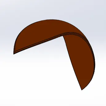
Features used to model Front fender
- Sketch
- Offset Entities
- Trim Entities
- Revolve boss / base
- Dynamic Mirror
- Split
- Fillet
- Appearances
Trim Entities
The trim type is selected based on the entities you want to trim or extend. Power trim is used to trim multiple, adjacent sketch entities by dragging the pointer across each sketch entity.
Revolve boss/ base
A revolved section is obtained when we rotate the sketch around any particular axis, centreline, sketch line or linear edge.
Dynamic Mirror
This tool allows us to mirror a sketch about a line while we are creating the sketch. Depending on design intent this tool can save an immense amount of time.
- Rear Fender
It has the same function as that of the front fender, but it is mounted on the rear part of the chopper above the rear wheel.
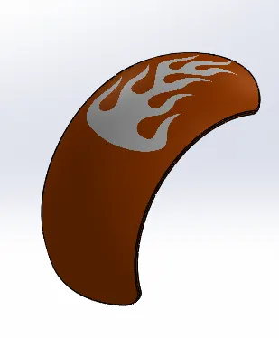
Features used to model Rear fender
- Sketch
- Offset Entities
- Trim Entities
- Revolve
- Split
- Fillet
- Shell
- Appearances
- Decals
Shell
It hollows out a part, leaves open the faces you select, and creates thin-walled features on the remaining faces. If you do not select any face on the model, you can shell a solid part, creating a closed, hollow model. You can also shell a model using multiple thicknesses.
Decals
A decal is a 2D image applied to a model. You can use decals to apply warning or instruction labels to models. You can use decals to create model details that you can represent with an image instead of with the model geometry, such as a car grill or a picture frame. You can view and apply decals in SOLIDWORKS. You can view decals in eDrawings and PhotoView 360.
- Chain
It is used to transfer mechanical power from the engine to the rear wheel of the chopper. Power from engine is transmitted to the chain with the help of a sprocket. Chain is a Positive Drive. It is comparatively more efficient than other transmission systems like Belt drive.
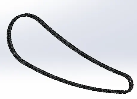
-
Features used to model Chain
- Sketch
- Trim Entities
- Extrude Boss/base
- Fillet
- Blocks
- Pattern (Curve Pattern)
- Mirror
- Body delete/Keep
- Appearances
Blocks
You can make, save, edit, and insert blocks for drawing items and sketch entities that you use often, such as standard notes, title blocks, label positions, and so on. You can attach blocks to geometry or to drawing views, and you can insert them into sheet formats.
Patterns
It is used for repeating the same entities again and again. Its types include Linear Pattern, Circular pattern, Curve Driven Pattern, Sketch Driven Pattern, Table driven Pattern, Fill Pattern, Variable Pattern. In curve driven pattern curves are the reference entities as paths on which the selected bodies, features or entities keep repeating until the curve ends.
Mirror
It is used to create exact replica of the features, faces and /or bodies about a face or plane.
Body delete/Keep
We can select bodies to keep or delete using the Delete/Keep Body feature. This is useful in working with multibody parts with multiple configurations.
- Oil Tank
It is used to store the oil required to run the engine. It is a hollow part with desirable thickness. In our Chopper thickness given is 3mm.
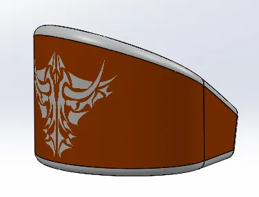
Features used to model Oil Tank
- Sketch
- Extrude boss/base
- Combine
- Fillet
- Shell
- Appearances
- Decals
Combine
The common function allows you to add two bodies together, and keep the area that is common to them. To use this feature, we will select the common button, and then under Bodies to Combine, select the required bodies to be combined.
- Pedal
Pedal allows the user to rest his/her foot on it. It also gives a platform from which shifting of gears and applying brakes are easily done.
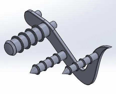
Features used to model Pedal
- Sketch
- Extrude boss /base
- Fillet
- Revolve
- Dome
- Chamfer
- Pattern (Linear)
- Appearances
Chamfer
The chamfer tool creates a bevelled feature on selected edges, faces, or a vertex.
Linear Pattern
We can use linear patterns to create multiple instances of one or more features that you can space uniformly along one or two linear paths.
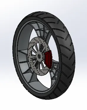
- Front Wheel
It is located in the front portion of the chopper used to provide motion to the Vehicle. This wheel helps to guide the vehicle according to the movement of the front fork as desired by the rider.
Features used to model Front Wheel
- Sketch
- Revolve
- Trim Entities
- Fillet Entities
- Extrude boss /base
- Revolved cut
- Linear Pattern
- Chamfer
- Fillet features
- Extrude cut
- Circular Pattern
- Combine
- Appearances
Revolved Cut
Revolved Cut feature is generally used for the cutting material from the geometry. It works as Revolved Boss/Base but the difference is, it is used for removing materials from parts.
Circular Pattern
Circular patterns are used to create multiple instances of one or more features that we can space uniformly around an axis.
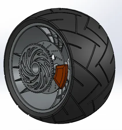
- Rear Wheel
Rear-wheel drive improves traction since most of the weight of the engine and transmission system is on the rear wheel (driven wheel). It offers better initial acceleration than front-wheel drive. Taking all these factors into consideration rear wheel is designed.
Features used to model Rear Wheel
- Sketch
- Linear pattern
- Trim
- Fillet Entities
- Planes
- Revolve
- Extrude boss /base
- Extrude Cut
- Circular pattern
- Combine
- Revolved cut
- Fillet
- Chamfer
- Fillet Features
- Appearances
Plane
We can create planes in part or assembly documents. We can use planes to sketch, to create a section view of a model, for a neutral plane in a draft feature, and so on.
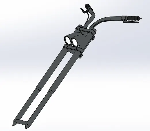
- Front fork
Front fork Consists of large hydraulic shock absorbers with internal coil springs. They allow the front wheel to react to hills and dales present on the surface of the road while isolating the rest of the motorcycle from that motion.
Features used to model Front Fork
- Sketch
- Revolve
- Extrude boss /base
- Trim
- Fillet
- Linear pattern
- Extrude cut
- Dome
- Revolve cut
- Plane
- Move / copy body
- Mirror
- Combine
- Projected Curve
- Sweep
- Appearance
Move / copy body
The ‘Move/Copy Body’ feature can be used to reorient geometry to the default planes. This will make it easier to locate in assemblies. Reorienting a part can also help with drawing view creation.
Projected Curve
It is a tool used to form 3D curves from two 2D curves from two different planes.
Sweep
A sweep is a tool that creates a solid, a cut or a surface feature by moving a profile along a path.
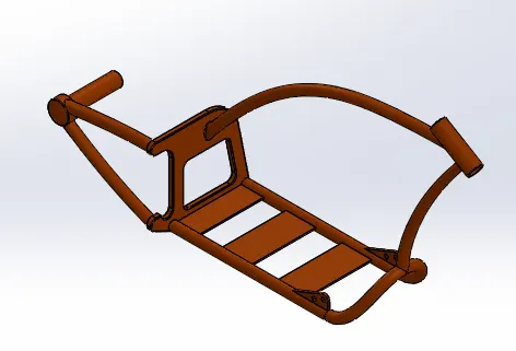
- Chassis
It is the frame or skeleton of the vehicle to which all the components of the motorcycle are attached. It also provides the required strength and rigidity to the chopper.
Features used to model Chassis
- Sketch
- Offset
- Projected curve
- Trim Entities
- Sweep
- Mirror
- Extrude boss /base
- Extrude Cut
- Chamfer
- Fillet
- Plane
- Dome
- Split
- Combine
- Appearance
- Engine
The engine is the most important component of the vehicle or you can say it is the heart of the vehicle. Power used for the motion of the chopper is generated from the engine i.e. chemical energy by burning fuel and later it is converted to heat energy. Further, this heat energy is converted into mechanical work which in turn produces rotational motion and thus it is transmitted to the wheel through the gearbox and clutch.
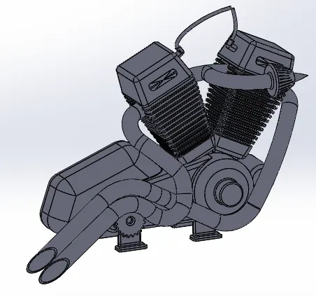
Features used to model Engine
- Sketch
- Convert Entities
- Extrude boss /base
- Fillet
- Revolve
- Plane
- Circular pattern
- Dome
- Extrude Cut
- Chamfer
- Offset
- Mirror
- Split
- Combine
- Sweep
- Projected Curve
- Composite curve
- Linear pattern
- Composite curve
Composite curve
This tool combines all sketch entities into one continuous curve.
- Fuel Tank
The fuel tank is the storage component of the vehicle and supplies the required fuel to the engine.
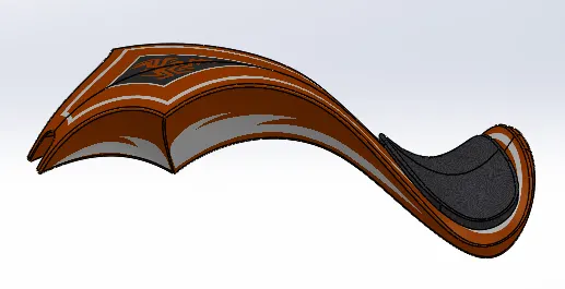
Features used to model Gas Tank
- Sketch
- Trim
- Projected Curve
- Convert Entities
- Plane
- Surface Extrude
- Boundary Surface
- Surface Sweep
- Surface Loft
- Surface Fill
- Surface trim
- Surface Knit
- Mirror
- Split
- Sweep cut
- Fillet
- Shell
- Decals
- Appearances
Surface Extrude
We can extrude the boundary edges of a face of a solid body or edges of a surface body in a customized direction.
Boundary Surface
The boundary surface feature lets you create surfaces that can be tangent or curvature continuous in both directions (all sides of the surface).
Surface Sweep
Sweep surfaces are surfaces that are generated from a section curve positioned along a path.
Surface Loft
Loft Surfaces are surfaces generated by multiple 3D Curves or existing edges creating a smooth tangency between the selected curves.
Surface Fill
The Filled Surface feature constructs a surface patch with any number of sides, within a boundary defined by existing model edges, sketches, or curves, including composite curves. This feature is mostly used to construct a surface to fill a gap in a model.
Surface trim
We can use a surface, plane, or sketch as a trim tool to trim intersecting surfaces. We can also use a surface in conjunction with additional surfaces, as mutual trim tools. The Trim surface includes the following modes: Standard & Mutual.
Surface Knit
Use the Knit Surface tool to combine two or more faces and surfaces into one.
Assembly of Chopper
Firstly, the chassis component is inserted in the assembly by using the insert part option and it is given appropriate mates with respect to assembly planes. After that, all other parts of the chopper are inserted one by one and given proper mates to restrict their motion.
Features used to Assemble Chopper
- Insert components
This feature is used to add components to assemblies.
- Mate
Mates are used to create geometric relationships between components of an assembly. Some of the mates used in our assembly are Co-incident mate, Parallel mate, Tangent mate, Concentric mate, Distance mate, Limit angle mate, width mate etc.
Rendering
- Rendering is the process of creating realistic images of the Photorealistic model with the environment.
- The two ways in which we can render the part/assembly in Solidworks are as follows
- Photoview 360.
- Solidworks Visualize.
- In the photorealistic model, some of the mates are changed to render a realistic model.
- Then the photorealistic model is rendered into realistic images with different views.
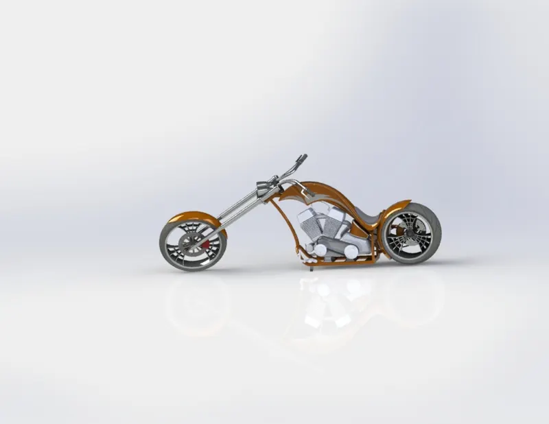
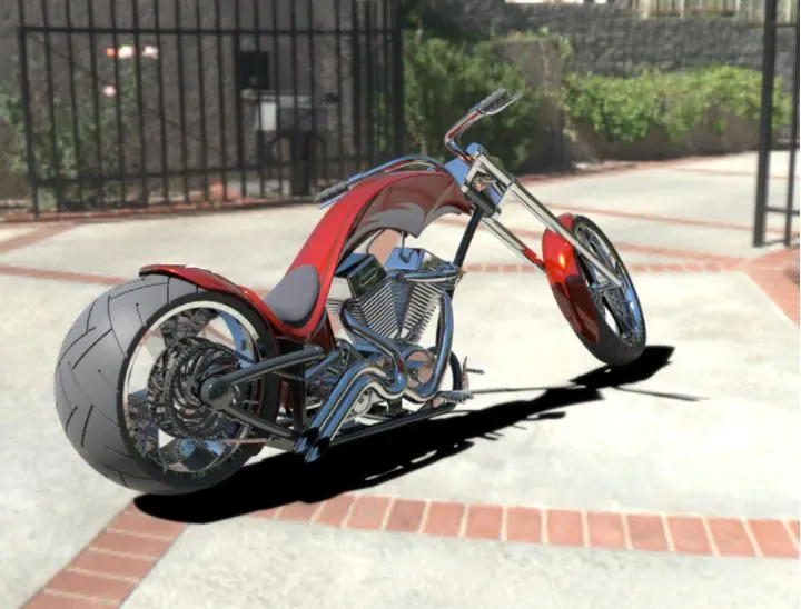
Conclusion
- The various parts of the chopper are sketched & modelled individually in Solidworks.
- The above parts modelled are inserted into the assembly environment and after applying proper mates they are assembled successfully and then decals are applied.
- The realistic images are rendered after setting up proper scenes and lightings with the help of Photoview 360 and Solidworks Visualize.