Roof challenge
Aim:
To design & develop the Roof of a car with its components by following the master section and design parameters.
Objective:
- To develop the essential flanges and reinforcements using roof styling as input.
- To do a curvature study on the roof and perform calculations to determine the position of the Bow-roof.
- To determine the Heat Distortion Criteria of the car's roof.
- To find the section modulus on the O-Y section of the roof and also for all the components of it.
- To determine the Snow Load Criteria for a car's roof.
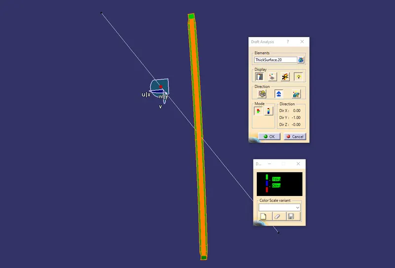
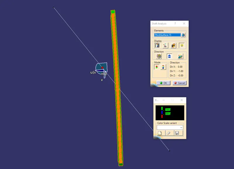
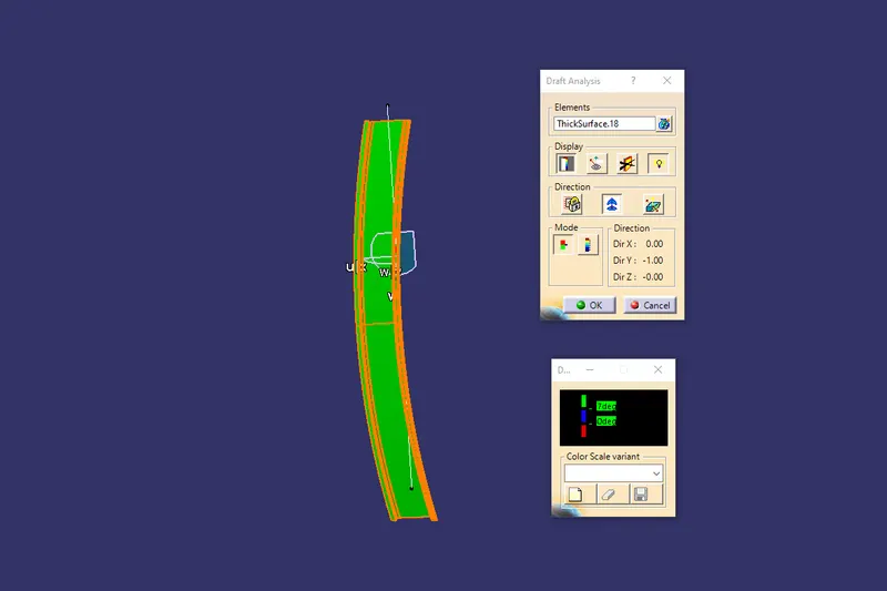
- To perform Draft Analysis on the final CAD model of the roof.
Introduction:
Car's Roof:
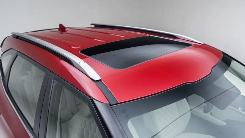
An automobile roof or car is the top portion of an automobile that sits above the passenger compartment, protecting the vehicle occupants from sun, wind, rain, and other external elements.
Heat Distortion Criteria:
The heat radiating from the sun causes the roof of the car to change in the metallic regions. Heat distortion criteria indicate what temperature materials start to "soften" when exposed to a fixed load at elevated temperatures.
W = [1.73 x 10^(-3) x L] + [1.85 x 10^(-8) x (R^2)/t] + [ 1.10x10^(-3) x l] - 2.68
Where
L = Roof Length in X-Direction[mm](Roof dimension in 0-Y)
R = Roof curvature
R = 2(Rx*Ry)/(Rx+Ry)
Rx = X curvature
Ry = Y curvature
t = Roof plate thickness [mm]
l = Bow Roof Span [mm]
Judgement Condition: OK< 2.7mm
Snow Load Criteria:
During Winter Season the snow gets clogged over the top surface/roof of the car and the snow has some mass on it. Due to this, the roof can fail if the snow load exceeds the capacity of the roof that was designed to sustain.
Qr = [Iy x t2] / [α x s x [(Rx + Ry)/2]2 x 10-8]
Where
α = My x Lx2 x 10-12 , My = Y(Ly-Y)
t = Roof plate thickness [mm]
Ly = Distance between the front and rear roof Rails on the Vehicle along with 0Y[mm]
Length of Roof panel with the centre point between Roof rail Front /Rear as the reference point of the front and the rear.
Lx = Distance between the Left and Right end of the roof on the Roof BOW [mm]
Width of the roof panel exposed on the surface.
Y = Distance front Front Roof Rail to Roof BOW[mm]
s = Distance for which Roof BOW bears divided load [mm]
s = L1/2 + L2/2
Iy = Geometrical moment of inertia of Roof BOW (Y cross-section )[mm4]
Rx = Lateral direction curvature radius of roof panel Y cross-section on Roof BOW [mm]
Roof panel curvature Radius of the Length Lx in Front view
Ry = Longitudinal Direction curvature radius of the Roof panel X cross-section on Roof BOW [mm]
Roof panel X curvature radius of length s in Side view
Judgement condition = Qr ≥ 3.1
250 ≤ s ≤ 380
Section Modulus:
Section modulus is a geometric property for a given cross-section used in the design of beams. Other geometric properties used in the design include an area for tension, radius of gyration for compression, and moment of inertia for stiffness. The Section modulus is defined as
S=I/Y
Where
S = Section Modulus
I = Moment of Inertia
y = Distance from the neutral axis to any given part.
Procedure:
Open the given model in CATIA V5 that is the styling surface of the car's roof.
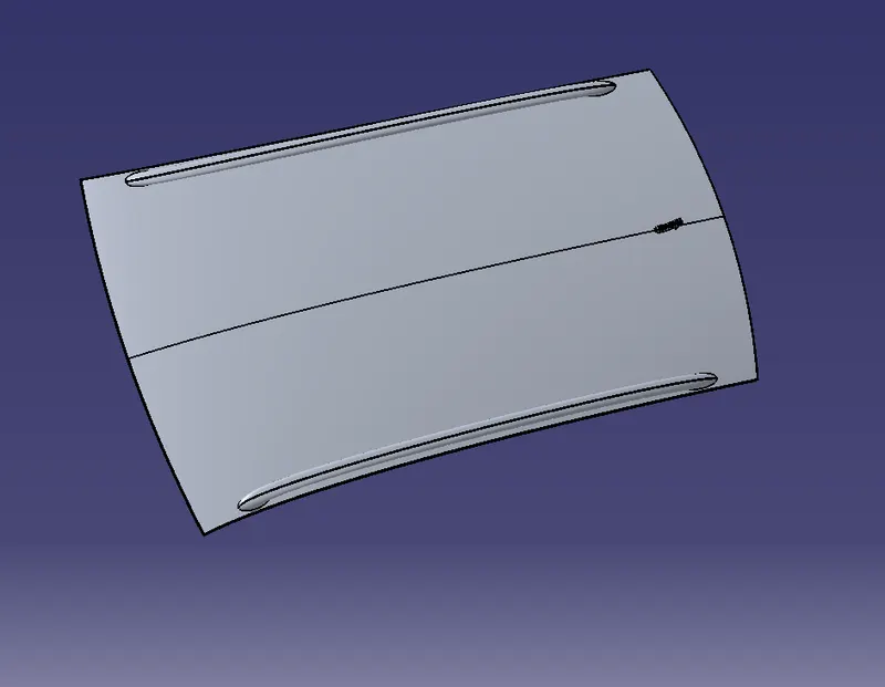
Roof Outer Panel:
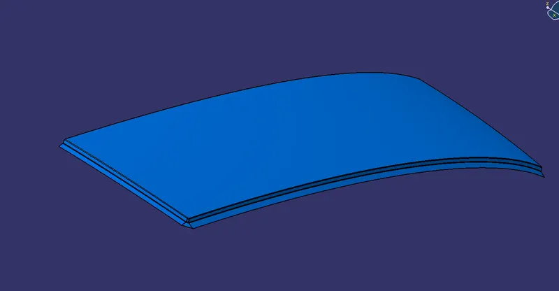
Front Roof Rail:
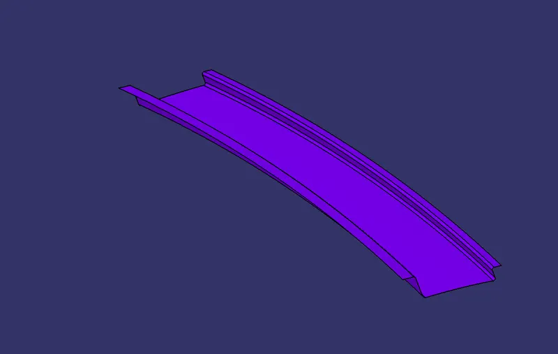
Center Roof Rail:
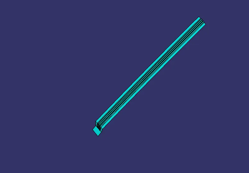
Rear Roof Rail:
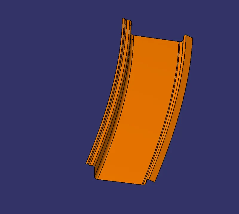
Bow Roof:
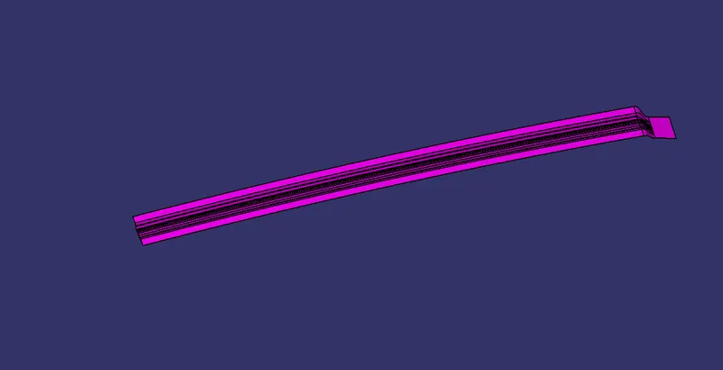
Solid-Body:
Once all the surfaces are created, use the symmetry option and mirror all the parts (individually) using the XY Plane and join them.
After mirroring all the surfaces successfully, use the thicken option to create the solids with the proper thickness.
The thickness for the Roof Outer Panel, front roof rail and rear roof rail is 0.75mm, for the bow roof, it is 1.25mm.
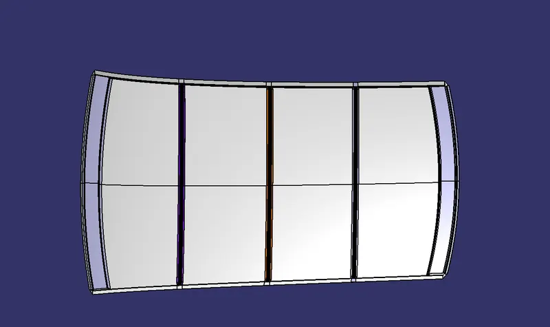
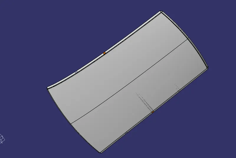
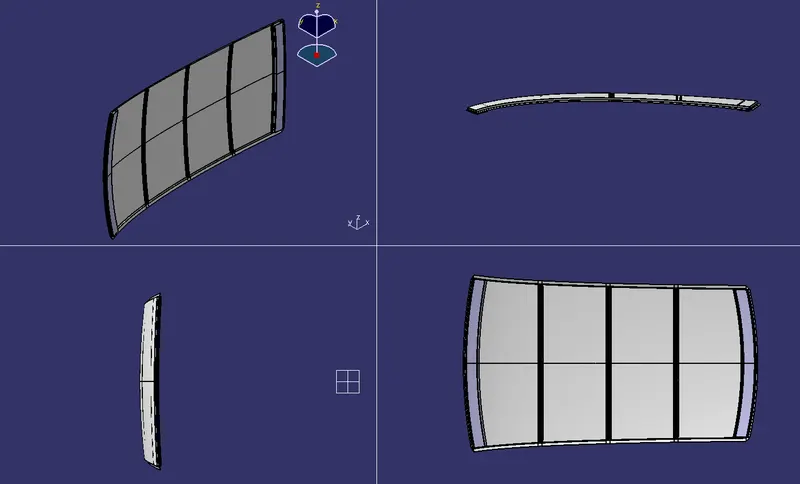
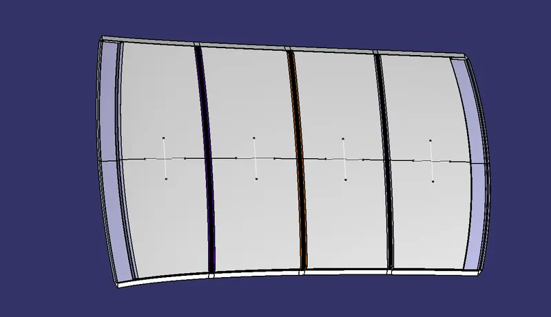
Different views:
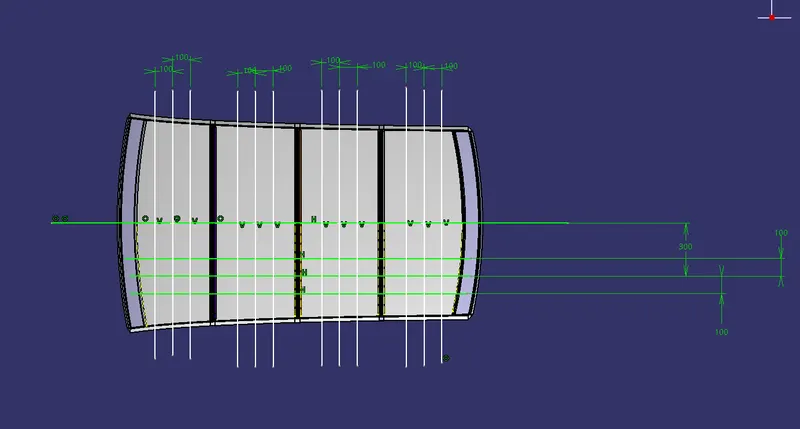
Calculating the Heat Distortion criteria:
- To calculate the Heat distortion criteria, we have to take a note of few values and note it down.
- To note down the values, first, we need to create a sketch.
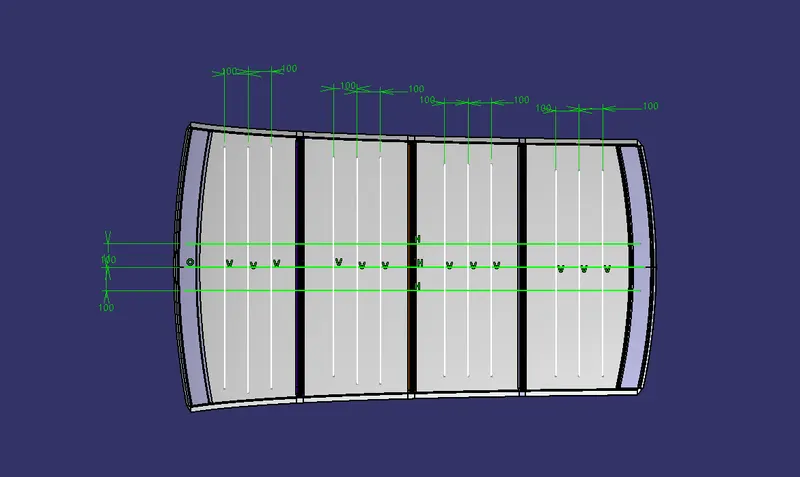
- Create a line at the center of the roof part in the 0-Y axis and then draw another line with a distance of 300mm to the O-Y line.
- Now create lines at a distance of 100mm on both sides to the 300mm line.
- Create a new sketch in which we need to create lines between the bow roofs and rails coming at the center. These lines need to be created in X-direction.
- Using these center line create lines at a distance of 100mm on both sides.
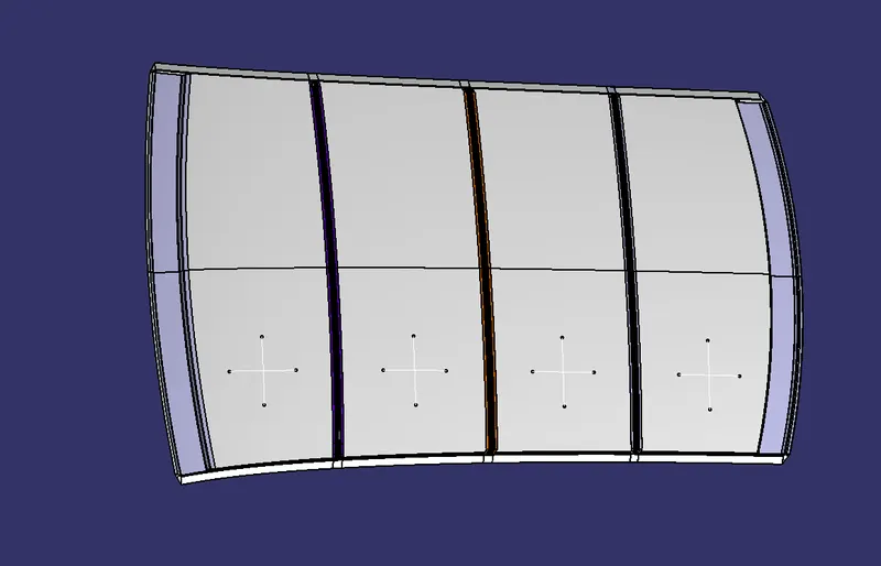
- Now intersect sketch 1 (lines in Y-direction) and sketch 2(lines in X-direction). This result will give us some points where the lines (X & Y)are coinciding with each other.
- Extract the required points and project them on the roof surface. Now using these points create a 3 point arc or circle and note the radius of the arc in the X direction as RxRx and in the Y direction as RyRy.
- Now since we got all the values for calculating the Heat Distortion, substitute these values to the below equation.
- W = [1.73 x 10^(-3) x L] + [1.85 x 10^(-8) x (R^2)/t] + [ 1.10x10^(-3) x l] - 2.68
| S.NO | BOW | L | Rx | Ry | R | t | l | R^2/t | W | OK/NG |
| 1. | F.R to BOW 1 | 2117.594 | 5735.524 | 2628.269 | 3604.704212 | 0.75 | 410.238 | 17325190 | 1.76 | OK |
| 2. | BOW 1 to C.R | 2117.594 | 4925.503 | 6385.607 | 5561.315633 | 0.75 | 456.503 | 41237642 | 2.26 | OK |
| 3. | C.R to BOW 2 | 2117.594 | 3945.439 | 10745.18 | 5625.34 | 0.75 | 3945.439 | 42192744 | 2.28 | OK |
| 4. | BOW 2 to R.R | 2117.594 | 3318.443 | 14245.1 | 5382.917387 | 0.75 | 273.325 | 38634293 | 2.00 | OK |
Calculating the Snow Load Criteria:
- To calculate the Snow Load Criteria, we have to take a note of few values and note it down.
- To note down the values, first, we need to create a sketch.
- Create a line at the center of the roof part in the 0-Y axis.
- Now using this O-Y line as a center create lines with a distance of 100 on both sides.
- Create a new sketch in which we need to create lines between the bow roofs and rails coming at the center. These lines need to be created in X-direction.
- Using these center line create lines at a distance of 100mm on both sides.
- Now intersect sketch 1 (lines in Y-direction) and sketch 2(lines in X-direction). This result will give us some points where the lines (X & Y)are coinciding with each other.
- Extract the required points and project them on the roof surface. Now using these points create a 3 point arc or circle and note the radius of the arc in the X direction as RxRx and in the Y direction as RyRy.
- Now since we got all the values for calculating the Snow Load Criteria, substitute these values to the below equation.
- Qr = [Iy x t2] / [α x s x [(Rx + Ry)/2]2 x 10-8]
| S.NO | BOW | ly | α | Lx | Ly | y | S | Rx | Ry | t | Qr | OK/NG |
| 1. | F.R to BOW 1 | 6251.35 | 0.87 | 1110.68 | 1923.11 | 496.938 | 502.695 | 4489.518 | 2673.741 | 0.75 | 62.68 | ok |
| 2. | BOW 1 to C.R | 6448 | 0.83 | 1072.662 | 1923.11 | 510.452 | 510.53 | 3774.198 | 833.065 | 0.75 | 14.098 | ok |
| 3. | C.RE to BOW2 | 6249 | 0.31 | 1052.201 | 1923.11 | 510.605 |
454.71 |
4289.698 | 11293.786 | 0.75 | 24.68 | ok |
| 4. | BOW 2 to R.R | 6250 | 0.61 | 1065.301 | 1923.11 | 398.82 | - | 4064.855 | 16054.301 | 0.75 | - | - |
Calculating the Section Modulus:
Section Modulus of Outer Roof Panel:
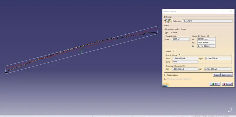
I=1549×103mm4
Y=1048.40mm
S=1477.48mm3
Section Modulus of Front Roof Panel:
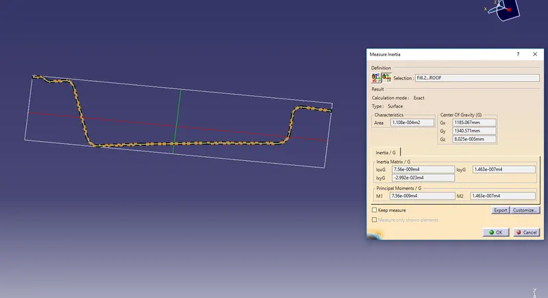
I=7.560×103mm4
Y=60.5mm
S=124.95mm3
Section Modulus of Rear Roof Panel:
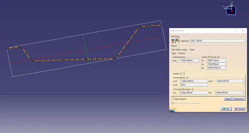
I=33640mm4
Y=106.5mm
S=315.86mm3
Section Modulus of Bow Roof 1:
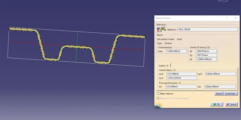
I=5700mm4
Y=40mm
S=142.5mm3
Section Modulus of Bow Roof 2:
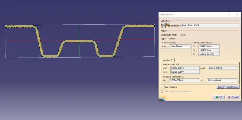
I=5727mm4
Y=40mm
S=143.175mm3
Draft Analysis:
Front Roof Rail:
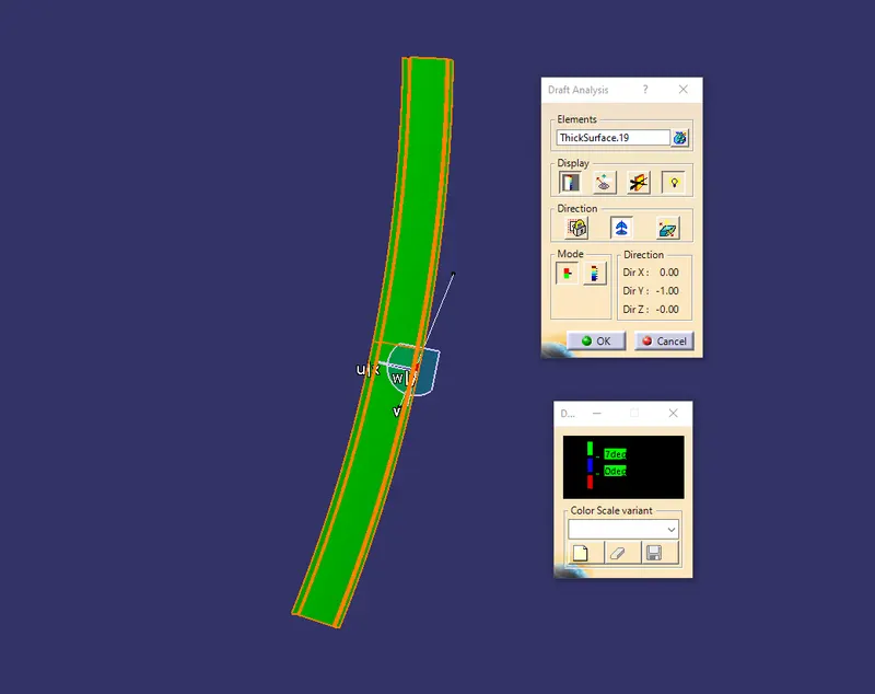
Bow Roof 1:
Center Rail:
Bow Roof 2:
Rear Roof Rail:
Result:
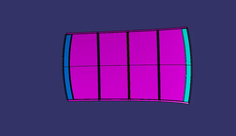
- The Roof of a car has been successfully developed with all the required components and a draft analysis have also been performed for the same.
- After performing the operations for determining the Heat Absorption Criteria, Snow Load Criteria and Section Modulus of all the components, the below results have been obtained.
Heat Distortion Criteria:
| S.NO | BOW | L | Rx | Ry | R | t | l | R^2/t | W | OK/NG |
| 1. | F.R to BOW 1 | 2117.594 | 5735.524 | 2628.269 | 3604.704212 | 0.75 | 410.238 | 17325190 | 1.76 | OK |
| 2. | BOW 1 to C.R | 2117.594 | 4925.503 | 6385.607 | 5561.315633 | 0.75 | 456.503 | 41237642 | 2.26 | OK |
| 3. | C.R to BOW 2 | 2117.594 | 3945.439 | 10745.18 | 5625.34 | 0.75 | 3945.439 | 42192744 | 2.28 | OK |
| 4. | BOW 2 to R.R | 2117.594 | 3318.443 | 14245.1 | 5382.917387 | 0.75 | 273.325 | 38634293 | 2.00 | OK |
Snow Load Criteria:
| S.NO | BOW | ly | α | Lx | Ly | y | S | Rx | Ry | t | Qr | OK/NG |
| 1. | F.R to BOW 1 | 6251.35 | 0.87 | 1110.68 | 1923.11 | 496.938 | 502.695 | 4489.518 | 2673.741 | 0.75 | 62.68 | ok |
| 2. | BOW 1 to C.R | 6448 | 0.83 | 1072.662 | 1923.11 | 510.452 | 510.53 | 3774.198 | 833.065 | 0.75 | 14.098 | ok |
| 3. | C.RE to BOW2 | 6249 | 0.31 | 1052.201 | 1923.11 | 510.605 |
454.71 |
4289.698 | 11293.786 | 0.75 | 24.68 | ok |
| 4. | BOW 2 to R.R | 6250 | 0.61 | 1065.301 | 1923.11 | 398.82 | - | 4064.855 | 16054.301 | 0.75 | - | - |
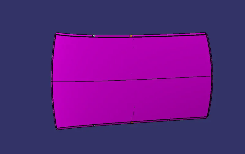
Final Body:
Conclusion:
- The results obtained after doing a curvature study on the roof was adequate.
- The position of the bow roofs can be arranged better (over the flat areas) which helps in increasing the strength of the roof.