Roof challenge
Project Title : CAR ROOF DESIGN.
Objective :
- For the given car roof styling design and develop the essential flanges and reinforcements, namely the Ditch area, Front Roof Rail, Rear Roof Rail, Centre Roof Rail and Bow-Roofs
- Do a curvature study on the roof and perform calculations for heat distortion and snow load criterion to determine and justify the position of the Bow-Roofs.
- Do a section modulus study for the master sections created for the Front Roof Rail, Rear Roof Rail, Bow Roof Rail and Centre Roof Rail.
- Perform Draft analysis of each reinforcement.
Software Used : NX CAD.
Introduction :
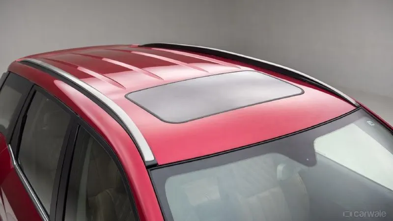
An automobile roof or car top is the portion of an automobile that sits above the passenger compartment, Protecting the vehicle occupants from sun, wind, rain, and other external elements. Under the styling surface that is seen from the outside, there are many other structures under the roof contribute to its strength and stability. The number of such reniforcement structures/supports differ with respect to the size of the vehicle. They are primarily installed on flatter areas of the enhance strength.
These are the Front Roof Rail, Rear Roof Rail, Centre Roof Rail, and Bow Roof Rail Design which are given mastics and spot-welded to roof flanges and ditch areas and improve NVH value by increasing the strength of the roof using mastic sealants.
Roof crush test for passenger car :
Safety point of view vehical roof plays a very crucial role especially rool over kind of accidents, in which vechicle tips over onto its side of the roof and vehicle rollover crashes are the cause of many fatalities and head, neck, and spine trauma around the world. Therefore, passenger safety is also a very important parameter in front of OEMs. Its not only a marketing strategy but also it is an obligation stipulated by international standards that are now placed in several countries, as well as a governmental Requirement. For this reason, strength is a very important criterion for designing avehicle roof. The strength of the roof structure of occupant protection in real-world rollover crashes, requiring the maximum moving distance of the roof structure should be less than 127mm (5in). When the induced load is 1.5 times the vehicle weight.
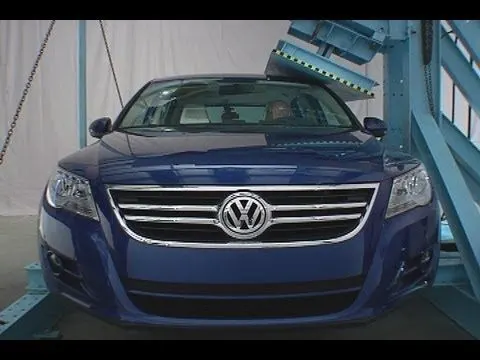
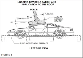
For the test, the passenger car shall be rigidly placed or positioned on a horizontal surface with the doors locked and the window closed. Furthermore, a flat, rigid block with a lower surface a rectangle measuring 30inches wide by 72 inches long (762mm x 1829mm) Shall not move more than 5 inches(127mm), measured as the distance between the original location of the lower surface of the test device and its location as the specified force level is reached, when it is used to apply a force of 1.5 times the unloaded vehicle weight(UVW) or 5000 lbs(22224N), which ever is less, to either side or forward edge of the vehicle.
This test can be conducted on either side of the roof structure, the front left or the front right side but not on both sides in one sigle test and still meet the requirements of the test. The rigid plate shall not move faster than 0.5 inches/sec and the force applied on the plate shall not exceed the lesser of 1.5 times the unloaded vehicle weight (UVW) expressed in kilograms multiplied by 9.8 or 5000lbs. Also, the direction of the forced shall be downward and perpendicular to the lower surface of the rigid plate and such that it moves in a straight line without rotation. The duration of the test shall not exceed 120sec. The longitudinal axis of the plate is pitched forward at a 5 degree angle as viewed from the side of the passenger acr as shown in below fig..,
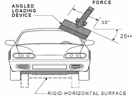
The lateral axis or the roll of the plate is such that it forms a25 degree outboard angle with a horizontal surface as viewed from the front of the passenger car as shown in below fig..,
Design Consideration of Roof :
- Thickness and Manufacturing Requirements :
- Thihckness of roof panel = 0.75mm.
- Reinforcement thickness = 0.75mm.
- Tool opening angle is 7 degree(min).
- Emboss depth should not exceed 6mm.
- No sharp Corners inside the component.
- Functional Requirements :
- Provide adequate clearance for the windshield glass joining with roof at front.
- Visibility criteria of windshield glass at front roof rail.
- Rear visibility criteria for rear roof rail.
- Head impact zone or head room clearance based on the trim parts.
- Mastic clearance to join the reinforcements.
Procedure :
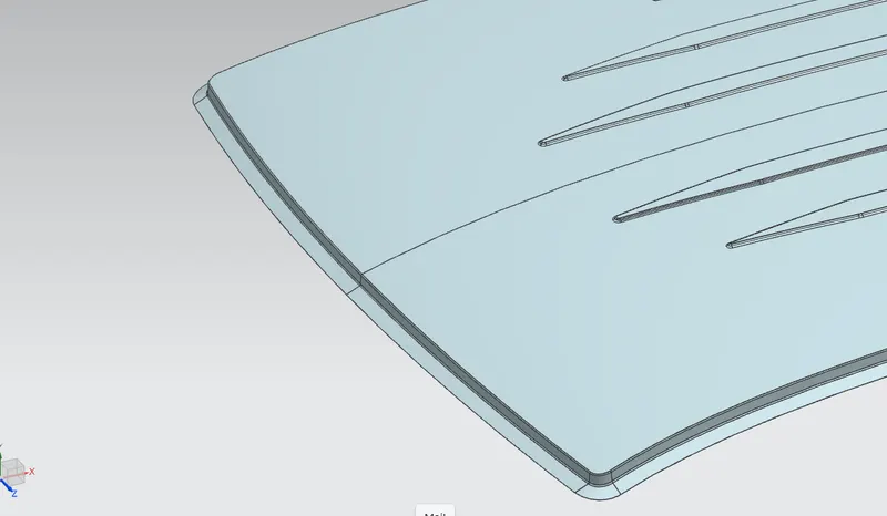
Front Ditch Area :
Front dump solid part class A surface is extracted and ditch area are developed considering the parameter specified in the following master section. The flange of around 15mm with the law extension command. Corner relief at rear flanges and positive draft more than 3 degree considering for the drawing operation process. Overall thickness of sheet metal consider 0.75mm throughout.
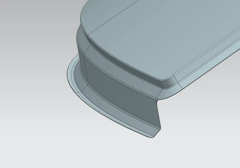
Rear Ditch Area :
Surface is offset from the outer panel to from the ditch area and with the law extension command relief at rear flanges and positive draft in required degree considering for the drawing operation process. Overall thickness of sheet metal for outer panel considern 0.75mm throughout.
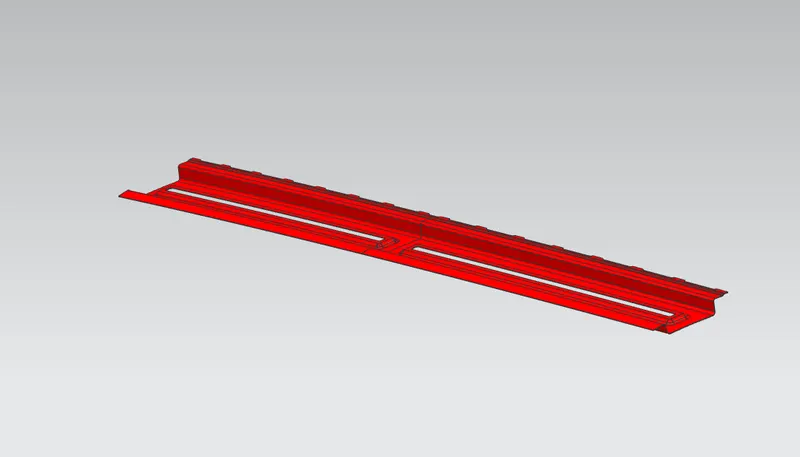
Front Roof Rail :
The front rail underpins the rooftop external shell at the front end. It is mounted with support rooftop rail fortification on the two closures. The rails are furnished with embosses to improve the strength over length and the rail is associated with the external board utilizing mastic sealant on one side and the other joinery is spot welded.
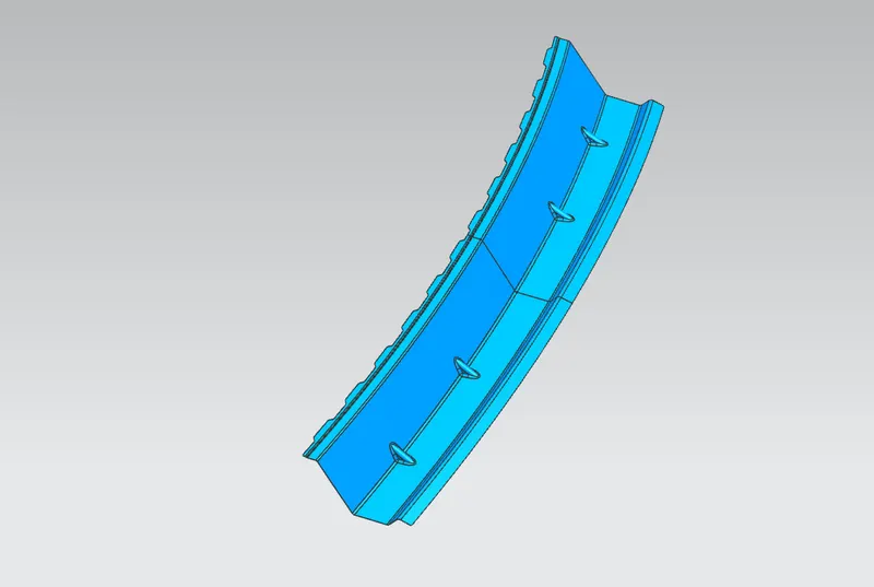
Rear Roof Rail :
It is the support which is joined to the back door and the body side outer and the inner panels. It is also usually made from body side outer scrap and therefore the thickness of the rail is 0.75mm. Similar to the front roof rail design, well have to take into consideration the rearheadroom clearance and the rear visibility criteria while designing the rear roof rail. Inputs are taken from the rear master section shown in fig..,
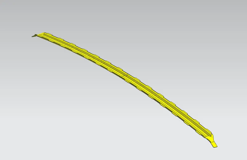
Bow Roof-1 :
The bow roofs are given to improve the torsional stiffness and load-bearing capasity of the roof structure. The number of bow roofs provided will depend upon the overall dimensions of the roof. longer the roof more the bow roofs are integrated to BIW frame they are attached to the outer panel using masting sealants. The positioning of bow roof is done based on curvature study. The heat distortion criteria and snow load criteria are checked to analysis the position of the bows in various conditions.
Bow Roof-2 :
The Bow roofs are given to improve the torsional stiffness and load-bearing capacity of the roof structure. The number of bow roofs provided will depend upon the overall dimenstions of the roof.
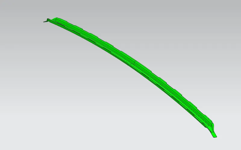
Centre Roof Rail :
Centre roof rail is provided to effectively support the flat area of the roof as it is more susceptible to failure under the action of the load. Usually, the centre reinforcement roof rail will be placed at the centre of the roof connecting the B pillar support structure which results in added support in the roll-over test.
Mastic Sealants :
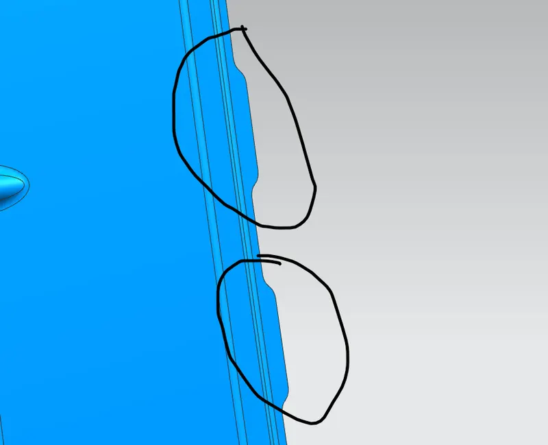
Bow roof rails and centre roof rail are joined with the help of mastic sealant. Here we cant's use the spot welding because it damages the A class area of the roof. So, the mastic sealant is used in this area.
CURVATURE STUDY :
Bow-Roof Prediction Formula :-
1) Heat Distortion Criteria :
W=[1.73*10^(-3)*L]+[1.85*10^(-8)*(R^2)/t]+[1.10*10^(-3)*l]-2.68
Judgement Condition : OK<2.7>3.1
Where,
L = Roof Length in X-Direction[MM](Roof dimension in 0-Y).
R = Roof Curvature.
R=2(Rx*Ry)/(Rx+Ry)
Rx = X curvature.
Ry = Y curvature.
t = Roof Plate Thickness [MM].
l = Bow Roof Span [MM].
Thickness for Roof :
Roof Outer Panel, t = 0.75MM
Front Roof Rail, t = 0.75MM
Bow Roof Rail-1, t = 0.75MM
Centre Roof Rail, t = 0.75MM
Bow Roof Rail-2, t = 0.75MM
Rear Roof Rail, t = 0.75MM
Rx and Ry(X and Y curvature) :
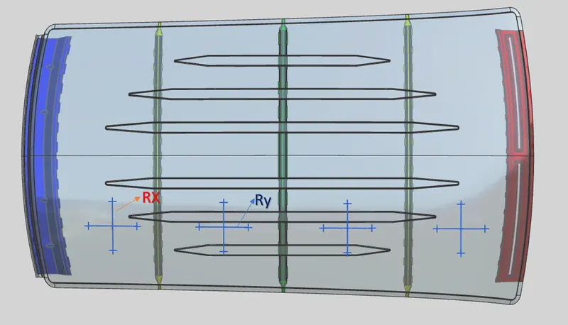
- From 0 -Y axis, at -3Y about distance 300mm is drawn parallel on the perpendicular plane as shown in fig., after that 100mm lines are offset to either side of-3Y line. Now center lines Are drawn between each adjacent roof rail edges respectively. Intersection points are marked on the sketch. Make all geometry in construction lines except the points.
- Project the intersection points in the sketch to roof surface as shown in fig.
- Joint the projected curves using arc curve and measure the minimum radius and linear dimension as follow and put into the formula to calculate "W".
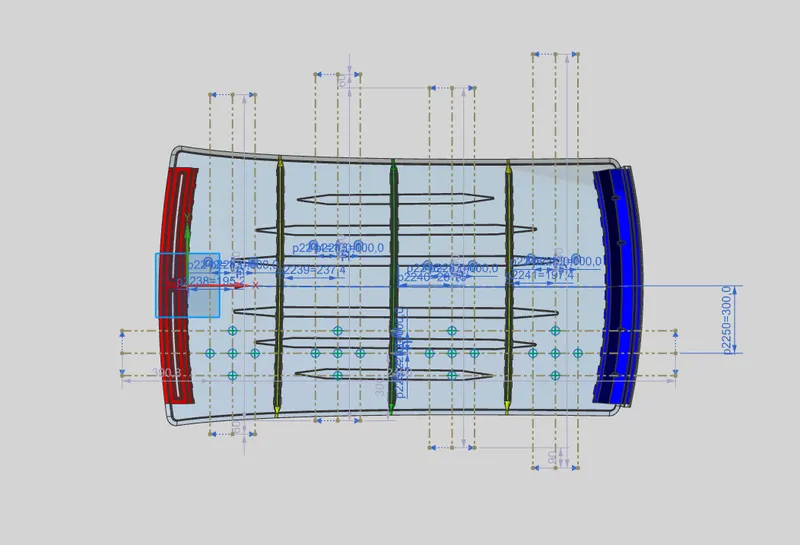
Finding the Rx and Ry Curvature with the tool simple radius. For example shown in the below figure.
Applying the values in the formula :
To find the heat distortion apply all the necessary values from the roof to the given formula.
Heat Distortion Criteria Calculations :
W=[1.73*10^(-3)*L]+[1.85*10^(-8)*(R^2)/t]+[1.10*10^(-3)*l]-2.68
R=2(Rx*Ry)/(Rx+Ry)
Table and calculations of Heat Distortion Criteria :

Snow Load Criteria :
Snow load criteria study is done to check the durability of the roof to withstand snowfall and reflex bak to its original shape without any permanent deformation once the load is removed.
Snow load prediction formula
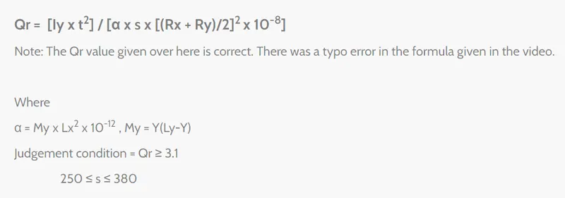
t = Roof plate thickness[MM].
Ly = Distance between the front and rear roof rails on the vehicle along with OY[MM].
Length of roof panel with the center point between roof rail front/rear as the front and rear reference point.
Lx = Distance between the left and right end of the roof on the roof BOW [MM].
Width of the roof panel exposed on the Surface.
Y = Distance front front roof rail to roof BOW[MM].
s = Distance for which roof BOW bears divided load[MM].
s = L1/2+L2/2
ly = Geometric moment of inertia of roof Bow (y cross-section)[MM].
Rx = Lateral direction curvature radius of roof panel Y cross-section on roof BOW[MM].
Roof panel curvature radius of the length Lx in front View.
Ry = Longitudinal Direction curvature radius of the roof panel X cross-section on roof BOW[MM].
Roof panel X curvature radius of length s in side view.
Rx and Ry (X & Y Curvature) :
- At O-Y axis on perpendicular plane to roof as shown in figure draw 100mm lines offsect to either side of OY axis line. Now centre lines are drawn between each adjacent roof rail edges respectively. Intersection points are marked on the sketch and exit the sketch. Make all geometry in construction lines except the points.
- Project the intersection points in the sketch to roof surface as shown in figure.
- Join the projected curves using arc curve and measure the minimum radius and linear dimension.
- Project the intersection plane bow roof and centre roof rail on the horizontal plane to find the moment of inertia of the respective section to find ly values.
- Put all the linear and radial dimension in following formula to calculate Qr value.
To find the Rx & Ry values taken the styling surface of the roof.
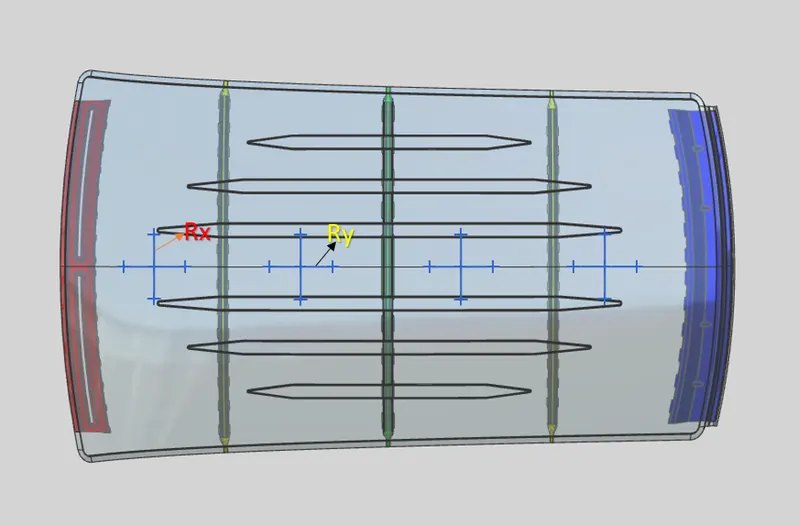
Table and Calculation of Snow load criteria :

It is observed from the values that obtained values of Qr>3.1
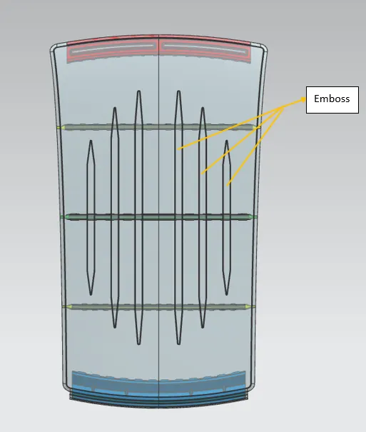
From the calculation we found BOW-1 and BOW-2 Roofs has NG, so we have to ask the styling team to modify the surface with curvature in y-axis. If team is rejected to do modification on curvature, we can provide emboss in the roof show in the below figure. The embosses are radically increased the strength of the roof.
Section Modulus :
Section modulus is a geometric property for a given cross-section used in the design of beams or flexural members. Other geometric properties used in the design include an area for tension and shear, the radius of gyration for compression, and the moment of inertia, and the polar moment of inertia for stiffness. Any relationship between these properties is highly dependent on the shape. There are two types of section moduli
- Elastic Section Modulus
- Plastic Section Modulus
The Elastic Section Modulus is defined as.
S=l/y
where,
S : is the Section Modulus.
l : is the section moment of area (or area moment of inertia, not to be confused with the moment of inertia)
y : is the distance from the neutral axis to any given fiber. It is often reported using y=c, Where c is the distance from the neutral axis to the most extreme fiber.
Calculation of Section Modulus :
1)Front Roof Rail :
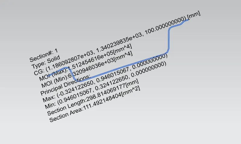
MOI(max) = 1.512454616*10^5 mm^4
MOI(min) = 6.320946036*10^3 mm^4
Y = 123.82mm
For Maximum MOI,
Smax = 1221.494602 mm^3
For Minimum MOI,
Smin = 51.04947534 mm^3
2) BOW-1 :
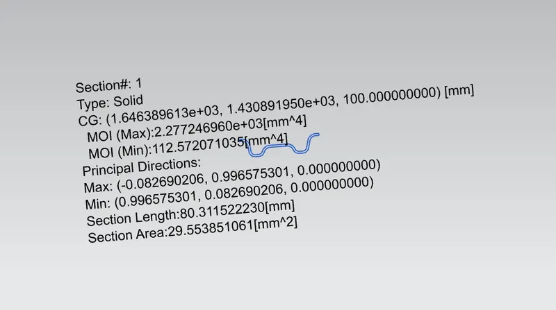
MOI(max) =2.277246960*10^3 mm^4
MOI(min) =112.572071035 mm^4
y = 29.22 mm
For Maximum MOI,
Smax = (2.277246960*10^3) / (29.22) = 77.947 mm^3.
For Minimum MOI,
Smin = (112.572071035) / (29.22) = 3.854 mm^3.
3) Centre Roof Rail :
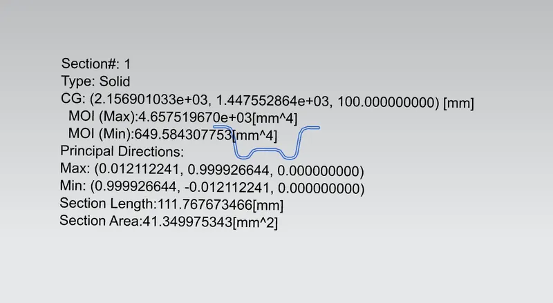
MOI(max) = 4.657519670*10^3 mm^4
MOI(min) = 649.584307753 mm^4
Y = 36.71 mm
For Maximum MOI,
Smax = (4.657519670*10^3) / (36.71) = 126.323 mm^3.
For Minimum MOI,
Smin = (649.584307753) / (36.71) = 17.619 mm^3.
3) BOW-2 :
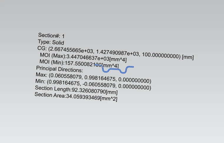
MOI(max) = 3.447046637*10^3 mm^4
MOI(min) = 157.550082136 mm^4
y = 35.21 mm
For Maximum MOI,
Smax = (3.447046637*10^3) / (35.21) = 97.912 mm^3.
For Minimum MOI,
Smin =(157.550082136) / (35.21) = 4.476 mm^3.
4) Rear Roof Rail :
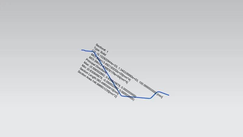
MOI(max) = 3.492130032*10^5 mm^4
MOI(min) = 2.406876178*10^4 mm^4
y = 167.62mm
For Maximum MOI,
Smax =(3.492130032*10^5) /(167.62) = 2083.415 mm^3.
For Minimmum MOI,
Smin =(2.406876178*10^4) / (167.62) = 143.595 mm^3.
Draft Analysis :
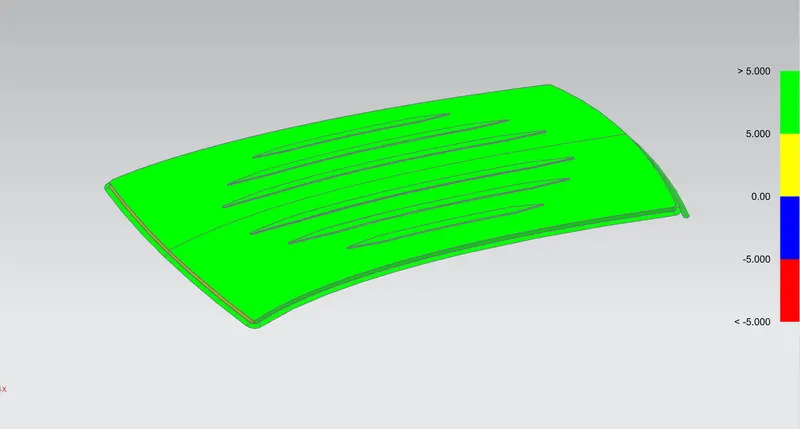
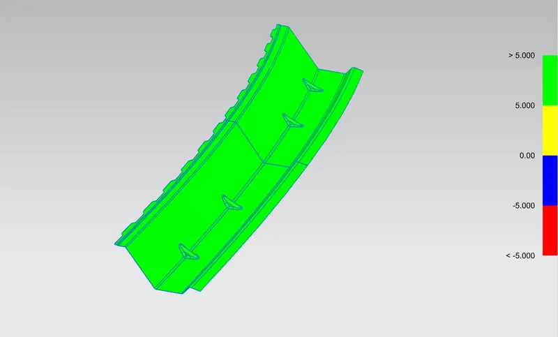
Minimum draft angle of 7 degree is considered for analysis. Green colour infer on the parts that all face along the tooling direction has positive draft angle greater than 7 degree and passed in analysis.
- Roof Outer Panel
- Front Roof Rail
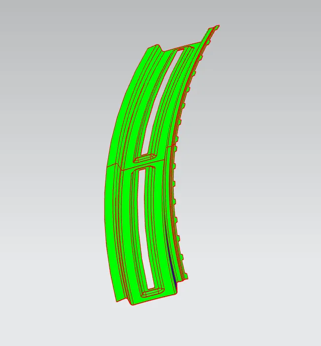
- BOW-1
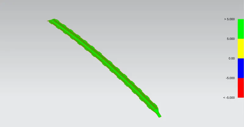
- Centre Roof Rail
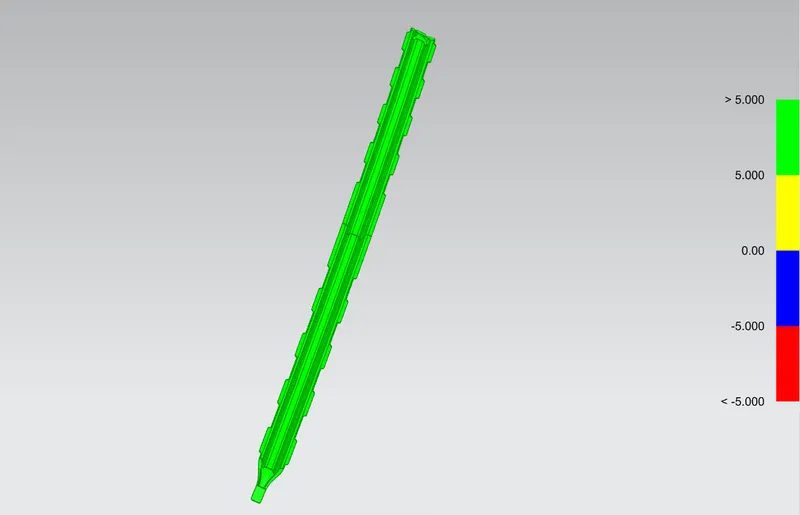
- BOW-2
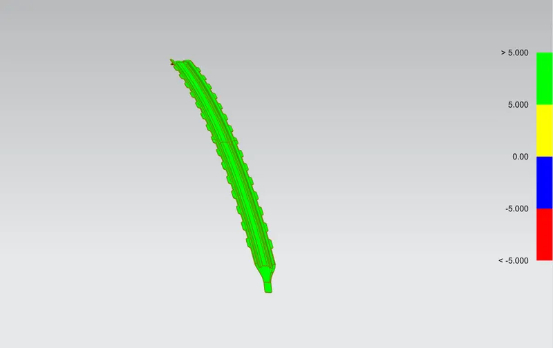
- Rear Roof Rail
CONCLUSION :
The Design of Front Roof Rail, Bow Roof Rails, Centre Roof rail, Rear Roof Rail, and Top Roof Panel are designed by following master section. As per Heat Distortion Criteria and Snow Load criteria, all Bow Roofs are in acceptable positions. Section Modulus and Draft analysis are carried out to check the feasibility of manufacturing are found Ok.
Link of Roof Assembly : https://1drv.ms/u/s!Aly1TzhZu9aOlBpsPY2WDWYeljSI?e=Fsjlxs