BiW Design of Roof of a car
Design of Roof
Design considerations:
A roof has been designed using the given styling (outer panel) part. The major features of the roof are as follows:
- Front Roof rail
- Rear Roof Rail
- Bow roofs
- Reinforcement center and
- Side flanges/ditch area.
The above listed components have been designed using the given master sections and appropriate dimensions. The flanges and embosses are given a positive draw angle of 25degrees to eliminate undercuts.
The bow roofs and reinforcement center rail are attached to the roof via spot welds for structural rigidity and mastic sealants to reduce noise and vibration.
The front and rear roof rails are connected to the roof by means of mastic sealants.
The below image shows the mirrored part of various features representing symmetricity.
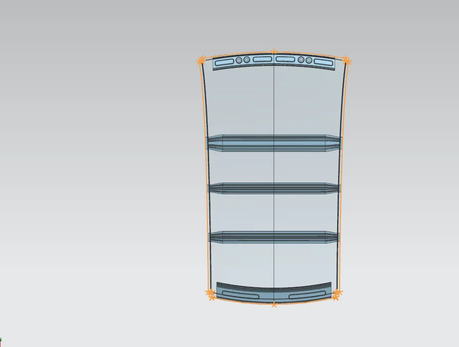
Fig 1: roof sew top view
Position of bow roofs:
The bow roofs’ position is determined by using the two prediction formulae conditions,
- Heat Distortion condition and
- Snow Load Condition
The reinforcement center is located at the B-Pillar of the car.
Further the position of the bow roofs are validated by the CAE team using Structural Analysis tools.
The prediction formulae along with values from the roof design have been illustrated in an excel sheet as a bow roof position calculator based on inputs mentioned.
Note: Please refer the attached excel sheet for calculations
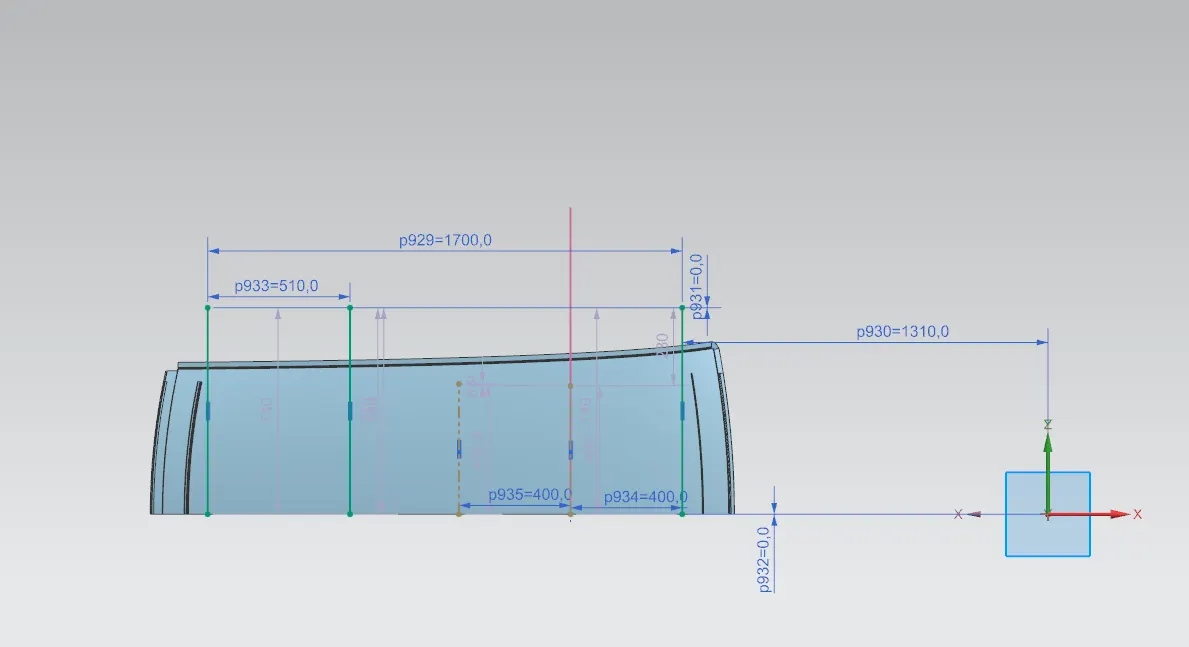
Figure 2: prediction of bow roofs’ position
Moment of Inertia Calculation: (Section Modulus Report)
The moment of inertia was calculated for the reinforcements with a sketch of their cross section along the O-Y direction/ Z plane.
The below images show the values obtained from the design and used in the calculations.
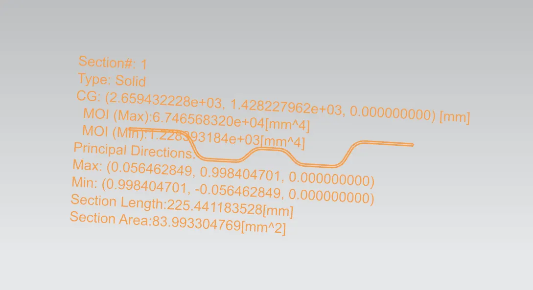
Figure 3: Moment of Inertia-Bow Roof
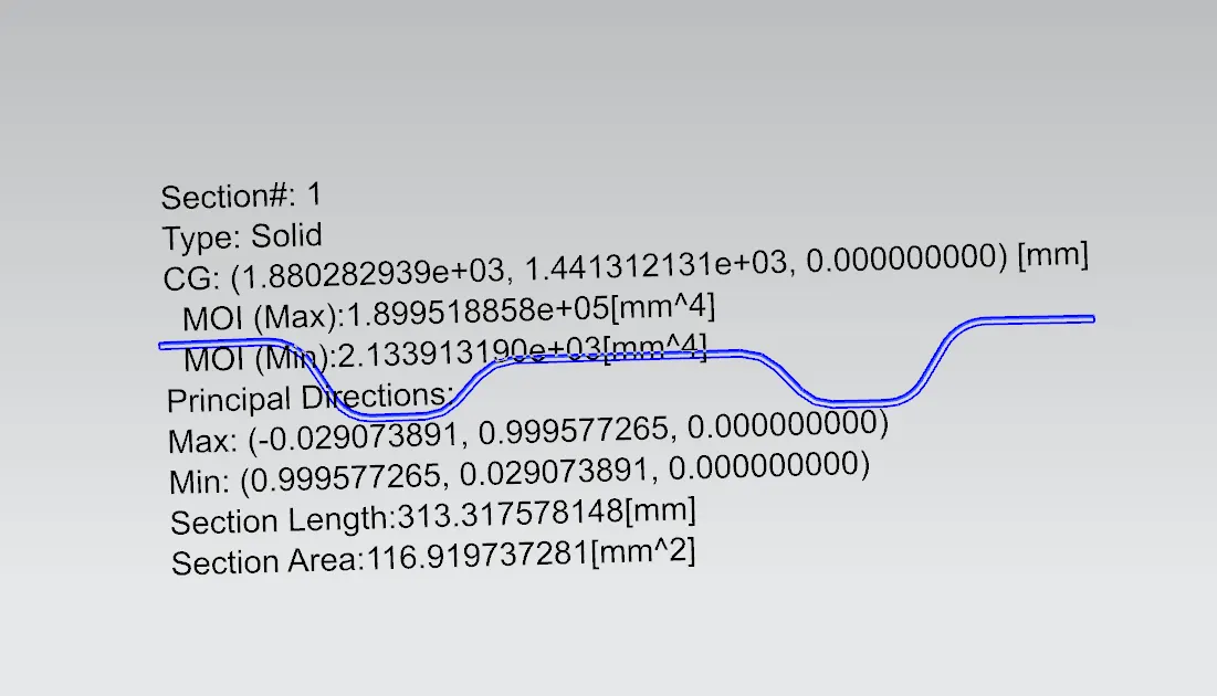
Figure 4: Moment of Inertia-reinforcement center
Draft Analysis:
Draft analysis was carried out using the tool in NxCAD to ensure that all the flanges, surfaces are of a minimum of positive 7degrees in the drawing direction.
Draft analysis of various features of the roof are as follow:
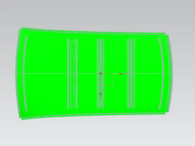
Figure 5: Draft analysis of Roof inner panel along Y direction
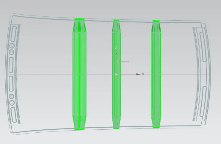
Figure 6: Draft Analysis of Bow roofs and Reinforcement Center along Y direction
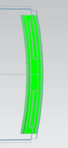
Figure 7: Draft Analysis of rear Roof Rail in Y direction
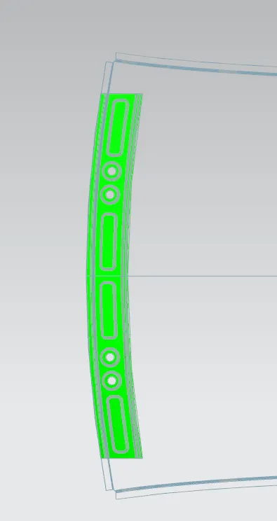
Figure 8: Draft Analysis of Front Roof Rail in Y direction
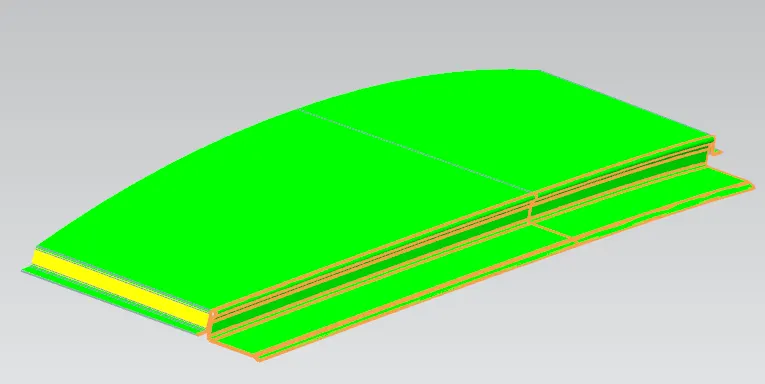
Figure 9: Draft Analysis of the Roof Flange near rear door trajectory area in X-direction