Roof challenge
ROOF DESIGN CHALLENGE
Introduction :
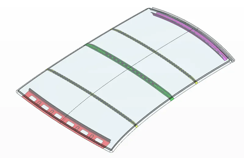
Based on the given roof styling, we are going to develop various reinforcements and perform section inertia analysis for the master section of each roof reinforcements. In order to check whether our design meets the regulations we will consider Heat distortion criteria and snow load criteria and determine the optimum positioning of the bow roofs. Finally we will also perform draft analysis on the roof outer panel to ensure the tooling feasibility.
Reinforcements that we will develop for the roof involves,
- Front roof rail
- Bow roof
- Centre reinforcement roof
- Rear roof rail
Major tests performed on the roof include Roof crush test in which loads are applied on the roof at specific angles defined by regulations and the displacement of the roof panel/reinforcements is measured to identify the strength of the design. If the displacement is high then increasing the thickness of the bow roof or increasing the number of mastics and spot welds is considered to reduce the displacement.
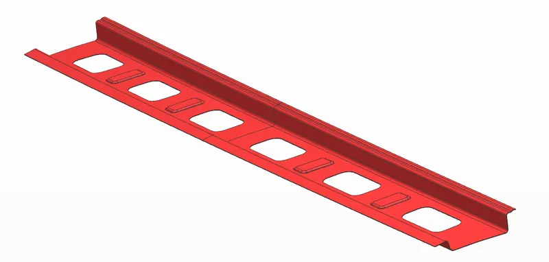
Front roof rail:
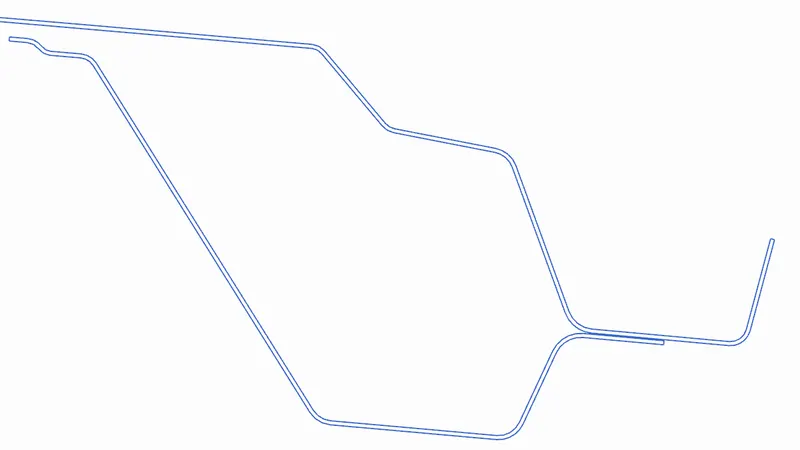
Front roof rail is connected to the windshield glass and the body side outer. It helps joining them and also acts as a supporting member for the car body. Usually, front roof rail is made from body side outer scrap to make savings on the material.
Every dimension for the front roof rail is fixed considering the windshield dimensions, rubber linings and mastics which will be placed on the front roof rail. The visibility of the driver will be affected if any of the dimensions is not met on the windshield mount flange. Head room clearance of the passenger is also considered while arriving at the dimensions of the roof rail. The front roof rail is joined with the outer panel using mastic so that the aesthetics of the roof is not spoiled and joined using spot welds with the side body frames.
Bow roof :
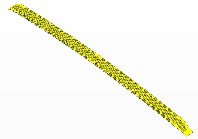
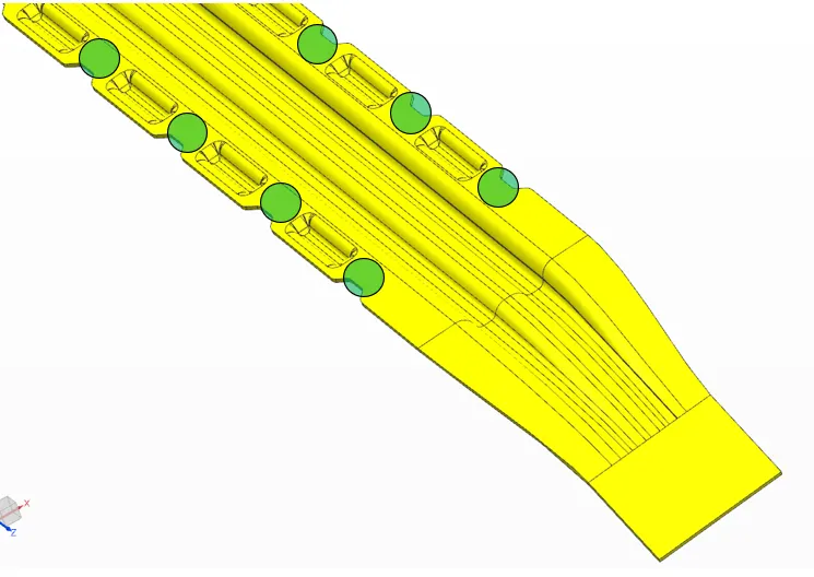
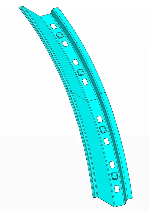
The bow roofs are the one which are placed between the front and rear roof rails. They play a major role in providing reinforcements to the middle region of the roof. Optimum positioning of the bow roof adds great strength to the total body and helps acheive required criteria for the roof regulations. The number of bow roofs is decided by the length of the car and also the curvature of the roof styling. Usally if the curvature is good in the front side then bow roofs are placed where there is more flatter area like after the centre reinforcement.
Center Reinforcement:
The Center reinforcement is another bow roof which is placed in the center of the roof styling to provide strength in the middle region. Sometimes the center reinforcement roof is welded with a bow roof and the bow roof is directly joined through mastics with the outer panel. This is done to provide added stregth to the middle area.
Rear roof rail:
Rear roof rail helps connect with the back door/tailgate and with body side outer.It acts as the supporting member for the body of the car and plays an important role to avoid deflection caused by the load on the roof outer panel. All the design parameters are similar to that of the front roof rail. Here also head room clearance of the passengers and the rear visibility is taken in to consideration when fixing various dimensions of the rear roof rail.
Sectional Moment of Inertia for the Bow roofs :
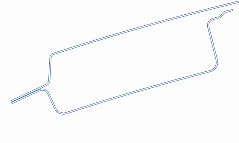
By taking section inertia on the bow roof we can understand the strength of the section when subjected to load. The important input we get from this analysis is the minimum moment of inertia values.
BOW ROOF 1 : (Between Front roof rail & centre reinforcement roof)
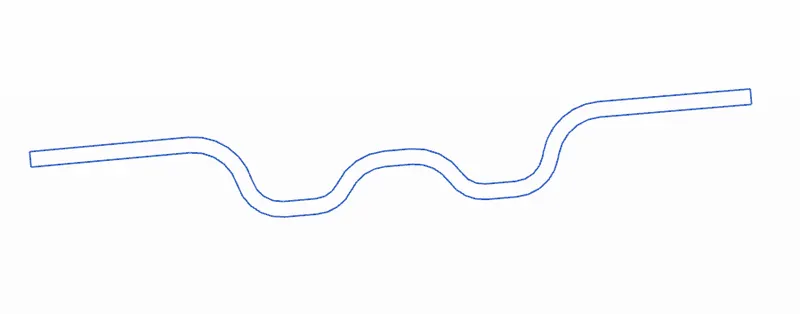
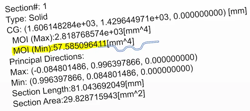
The minumum moment of inertia for our bow roof section is MOI : 57.585 mm^4. We use this value in the snow load criteria to identify the strength of the bow roof agaist deflection.
CENTRE REINFORCEMENT ROOF:
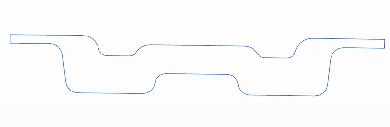
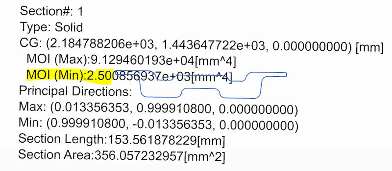
The minumum moment of inertia for our center reinforcement section is MOI : 2.5 x 10^3 mm^4. As we can notice that MOI is much better than the bow roof 1 as here we have two reinforcements welded together which means increased sectional area and also improved strength to avoid any deflection.
BOW ROOF 2 :
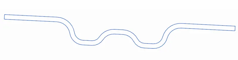
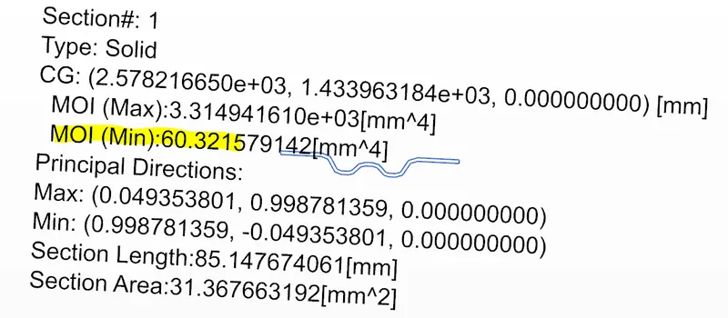
The minumum moment of inertia for our second bow roof section is MOI : 60.321 mm^4. Again here the MOI value is small and this will directly impact the snow load criteria we consider for measuring the strength of bow roof. By increasing sectional area it is possible to achieve improved moment of inertia.
Draft analysis for the roof outer panel:
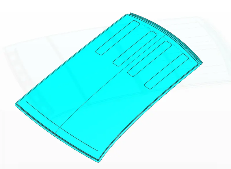
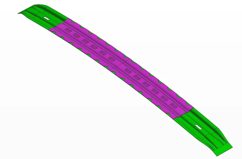
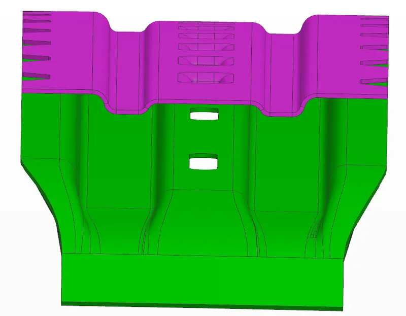
To make sure the roof outer panel is manufacturable, we need to satisfy the draft angle so that the body can clear the tooling. For the roof we need a minimum of 3 degree opening for the tool to release the part at ease.
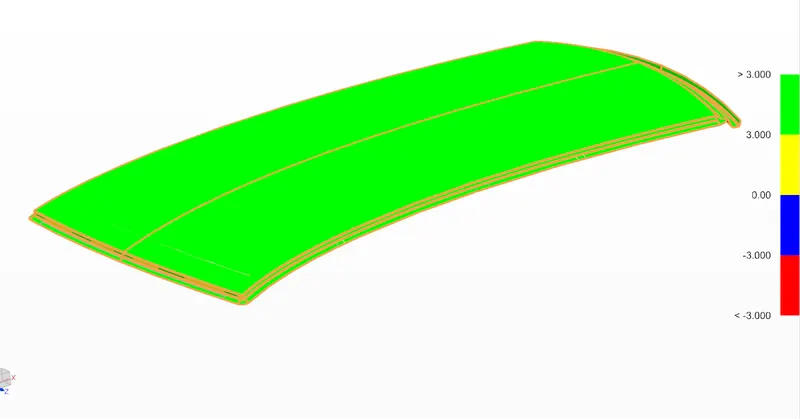
As we can see, the green color is predominant which indicates most of the surface has a draft value above 3 degrees.
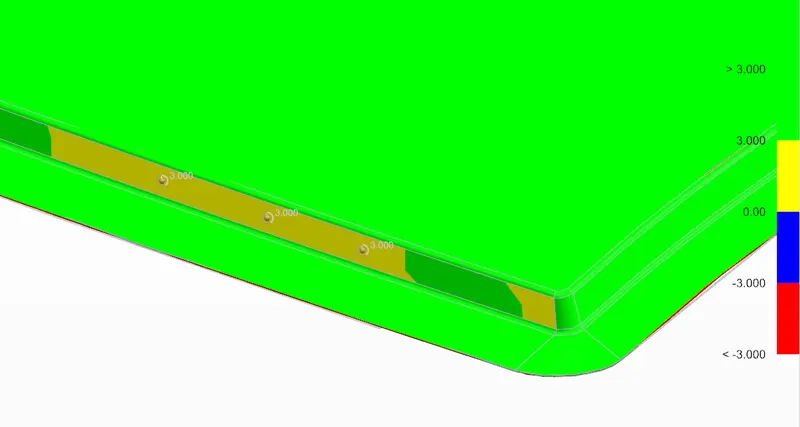
On some surfaces there is yellow color which indicates the minimum draft is exactly 3mm as it is measured on the image.
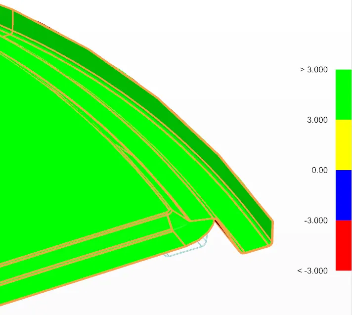
Our outer roof panel satisfies the draft requirement and hence we can assume it is toolable.
HEAT DISTORTION CRITERIA :
In order to check our design whether our bow roof positioning can satisfy the heat distortion value. We perform the below calculations.
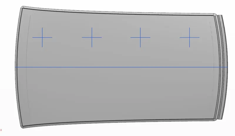
- Initially divide the entire roof styling in to equal areas with 3 or 4 lines considering the position of the bow roofs.
- Now offset the 0Y curve of the roof styling by 300mm to the right.Then take two offsets of the same curve 100mm apart.
- Make intersection points where the 300mm and 100mm offset curves meets the vertical lines(X direction)
- Connect these points by making a arc and measure their radius. This gives the Rx and Ry values which are radius if curvature along X and Y axis required for our calculation.
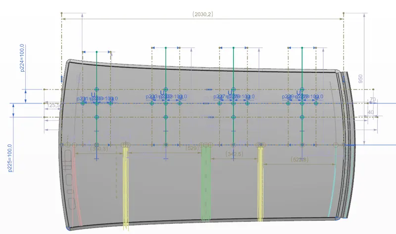
W = [1.73 x 10^(-3) x L] + [1.85 x 10^(-8) x (R^2)/t] + [ 1.10x10^(-3) x l] - 2.68
Where,
L is the length of the roof styling along 0Y plane
R is the effective radius of curvature obtained from Rx and Ry
I is the bow span which refers to the distance between bow roof's one end to next one.
| L | Rx | Ry | R | I(Bow roof span) | W | OK/NG | |
| Front roof rail & Bow roof | 2030.2 | 5738.5 | 2309.87 | 3293.88 | 350.3 | 1.4851 | OK |
| Bow roof 1 & centre reinforcement | 2030.2 | 4984.67 | 6147.5 | 5505.35 | 529 | 2.16151 | OK |
| centre reinforcement & bow roof 2 | 2030.2 | 4034.35 | 10293.4 | 5796.74 | 342.5 | 2.0377 | OK |
| Bow roof 2 & rear roof rail | 2030.2 | 3281.10 | 14582.23 | 5356.86 | 522.8 | 2.1151 | OK |
Our design satisfies the heat distortion criteria since all the values for W is below 2.7mm which is the requirement. So this helps us make sure that our design is safer.
SNOW LOAD CRITERIA:
Similar to heat distortion we perform snow load criteria to understand the snow bearing capactiy of our roof designed for the cold countries.To measure the radius of curvature of our bow roofs, we follow as below
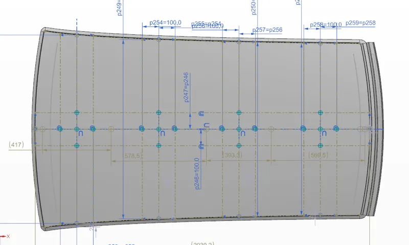
- Here we consider the 0Y curve of the roof styling as the primary area of testing and offset the curve 100mm apart on both sides.
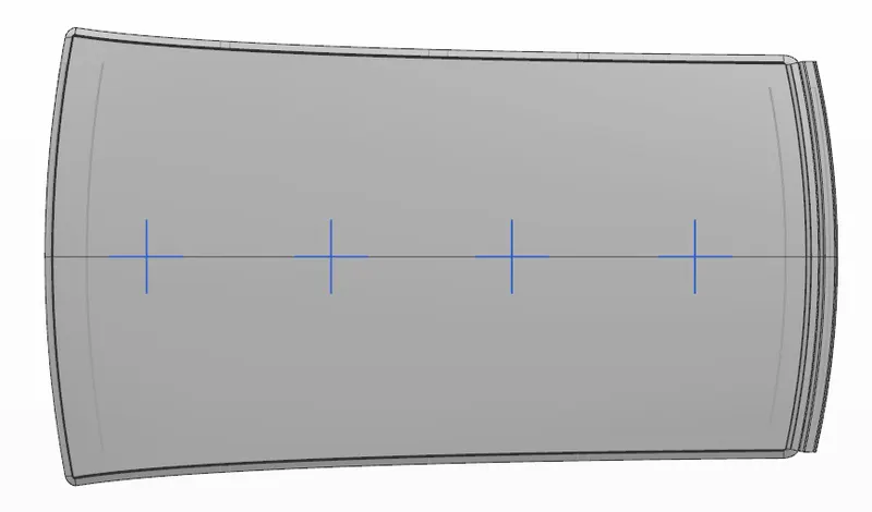
- Divide the entire roof styling in to equal areas with 3 or 4 lines considering the position of the bow roofs just the same as in heat distortion.
- Now make intersection points where the 100mm offset curves meets the vertical lines(X direction)
- Connect these points by making a arc and measure their radius. This gives the Rx and Ry values which are radius if curvature along X and Y axis required for our calculation.
Qr = [Iy x t^2] / [`alpha`x s x [(Rx+Ry)/2]^2 x 10-8`
α = My x Lx2 x 10-12 , My = Y(Ly-Y)
s = L1/2 + L2/L1
Iy = Geometrical moment of inertia of Roof BOW (Y cross-section )[mm4]
| Iy | Y | My | alpha | Lx | Ly | L1 | L2 | s | Rx | Ry | Iy x t^2 | Denominator | Qr | OK/NG | |
| Front roof rail & Bow roof | 57.585 | 417 | 672.404x10^3 | 0.87869 | 1142.9 | 2030.2 | 417 | 578.5 | 497.75 | 4686.83 | 2390.30 | 32.391 | 23.091 | 1.402 | NG |
| Bow roof 1 & centre reinforcement | 2.5x10^3 | 578.5 | 839.808x10^3 | 0.9922 | 1087 | 2030.2 | 578.5 | 393.3 | 485.9 | 3762.43 | 6054.71 | 1406.25 | 69.308 | 20.289 | OK |
| centre reinforcement & bow roof 2 | 60.3215 | 393.3 | 643.792x10^3 | 0.7222 | 1059.2 | 2030.2 | 393.3 | 569.5 | 481.4 | 4247.72 | 10729.52 | 33.930 | 80.227 | 0.4229 | NG |
| Bow roof 2 & rear roof rail | 1043.6 | 2030.2 | 569.5 | 4007.82 | 16386.53 |
The Values obtained for the Qr tells us that the front and rear area of the bow roofs do not satisy the required snow load criteria. The values should be >3.1.
Solution :
We can have three solutions to satisy the snow load criteria.
- By modifying the position of the bow roof it is possible to achieve the required snow load condition.
- From the calculations we can also see that the section inertia of the Bow roof 1 and Bow roof 2 have lower values.By improving the moment of inertia across this section we can satisfy the snow load condition.
- By giving aesthetic emboss on the roof styling we can drastically improve the strength of our design in order to compensate the failure in snow load criteria.Since our design satisfies the Heat distortion condition ,changing the bow roof position will affect this and hence I am going with emboss on the roof outer panel to provide additional strength since the snow load criteria is not met.