Roof challenge
OBJECTIVE:
To create the roof of a car in NX CAD with the roof skin and dimensions provided and also to calculate the heat distortion and snow load criteria and perform draft analysis.
ROOF:
A roof of a car is a part which covers the top of the car completely in order to prevent us from various weather conditions, dust, air and other foreign particles to enter into the car. It also improves the strength of the car by providing support to the car body thus helps in reducing the damage while crashing. It also provides the mounting for front and rear windshields.
ROOF PARTS:
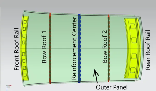
- Roof outer panel
- Front roof rail
- Bow roof
- Reinforcement center
- Rear roof rail
- Sun roof (optional)
ROOF OUTER PANEL:
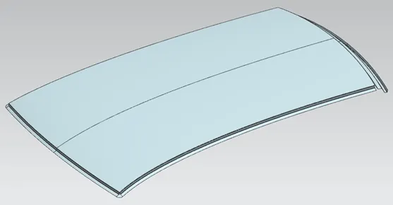
It is the top layer of the roof which covers the car. Sun roof and antenna are also placed on this outer panel. 3 degree of draft angle is provided for the front side of roof panel. The thickness value is taken as 0.75mm for the entire roof part.
FRONT ROOF RAIL:
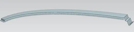
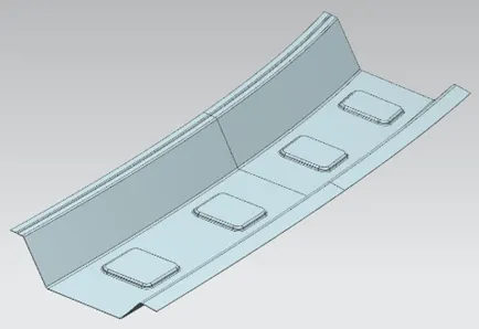
It provides support to the front part of the outer roof panel. While designing this part, the position and curvature of front windshield, head room clearance and visibility of driver and co-driver are taken into considerations. Embosses are provided to improve its strength.
BOW ROOF:
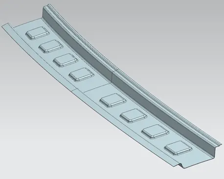
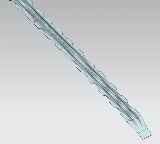
Bow roof is a supporting structure provided for the outer roof panel. It is attached to the outer roof panel by applying mastic sealants between them. Some cuts are provided on the bow roof to indicate the position of the mastic sealant. There should be a gap of 5mm for applying the sealants. In my design, two bow roofs are provided. The number of bow roofs may vary according to the design.
REINFORCEMENT CENTER:
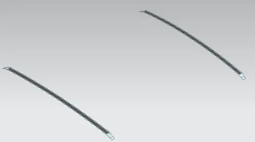
This is also a supporting structure provided for the outer roof panel at the center. This also follows the same designing criteria as the bow roof. But, only one reinforcement center is produced and even avoided in roof of smaller cars with good curvature. Sometimes, it may also integrated with the bow roof.
REAR ROOF RAIL:
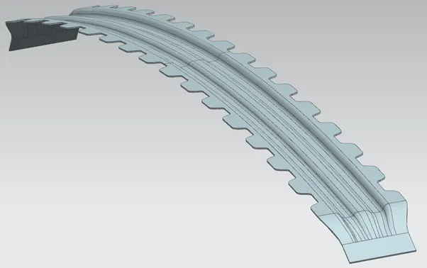
It gives the support for the outer panel at the rear end. It is bigger and stronger than the front roof rail as it provides mountings for rear windshield and back door. Embosses are provided to improve its strength.
HEAT DISTORTION CRITERIA:
This calculation is done for predicting the bow roof position at conditions of load applied at elevated temperature.
Bow-roof prediction formula
W = [1.73 x 10^ (-3) x L] + [1.85 x 10^ (-8) x (R^2)/t] + [1.10x10^ (-3) x l] - 2.68
Judgement Condition: OK< 2.7> 3.1
Where
L = Roof Length in X- Direction [mm] (Roof dimension in 0-Y)
R = Roof curvature
R = 2(Rx*Ry)/ (Rx+Ry)
Rx = X curvature
Ry = Y curvature
t = Roof plate thickness [mm]
l = Bow Roof Span [mm]
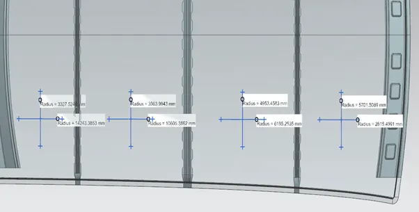

From the above calculations, we can infer that the roof created satisfies the heat distortion criteria at all positions.
SNOW LOAD CRITERIA:
This calculation is also done for the bow roof position in conditions of load applied by the snow on the bow roof.
Snow load Prediction formula
Qr = [Iy x t2] / [α x s x [(Rx + Ry)/2]2 x 10-8]
Where
α = My x Lx2 x 10-12, My = Y(Ly-Y)
Judgement condition = Qr≥ 3.1
250 ≤ s ≤ 380
t = Roof plate thickness [mm]
Ly = Distance between the front and rear roof Rails on the Vehicle along with 0Y [mm]
Length of Roof panel with the center point between Roof rail Front /Rear as the front and rear reference point.
Lx = Distance between the Left and Right end of the roof on the Roof BOW [mm]
Width of the roof panel exposed on the surface.
Y = Distance front Front Roof Rail to Roof BOW[mm]
s = Distance for which Roof BOW bears divided load [mm]
s = L1/2 + L2/L1
Iy = Geometrical moment of inertia of Roof BOW (Y cross-section )[mm4]
Rx = Lateral direction curvature radius of roof panel Y cross-section on Roof BOW [mm]
Roof panel curvature Radius of the Length Lx in Front view
Ry = Longitudinal Direction curvature radius of the Roof panel X cross-section on Roof BOW [mm]
Roof panel X curvature radius of length s in Side view
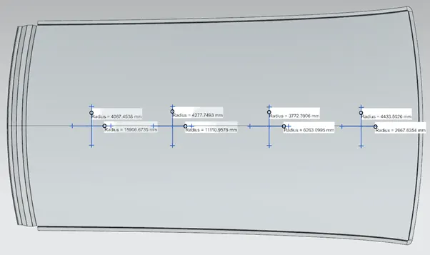

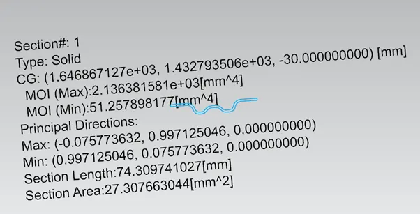
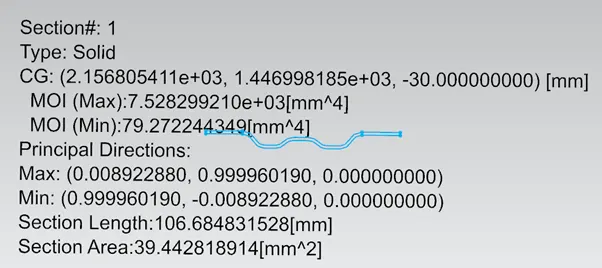
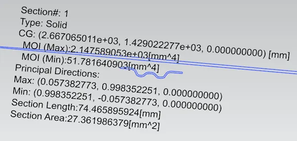
From the above calculations, we can infer that the roof created does not meet the snow load criteria at all positions. So, we should change the position of bow and reinforcement center or create an emboss on the outer panel to meet the requirements.
DRAFT ANALYSIS:
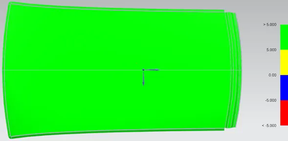
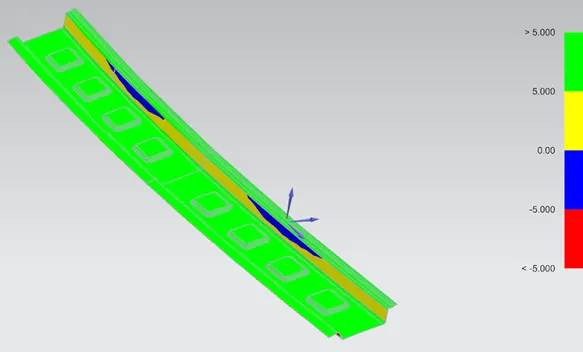
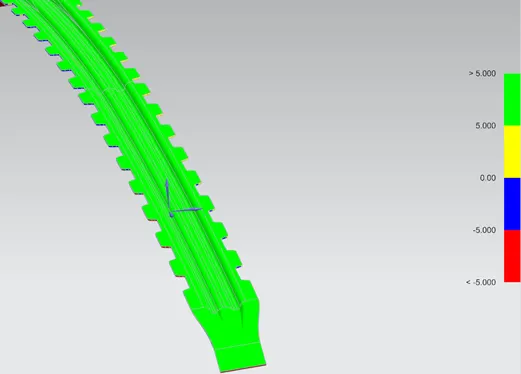
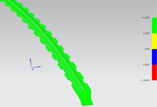
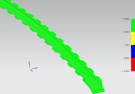
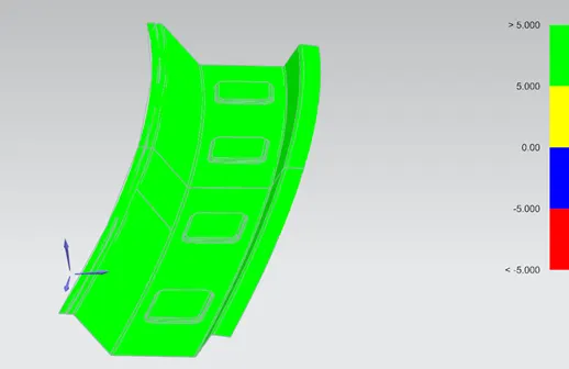
It is an analysis which shows that whether the part can be produced or not, with respect to the tool direction and angle. The green and yellow regions show the positive draft angle while the blue and red regions show the negative draft angle.
ROOF ASSEMBLY:
CONCLUSION:
Thus the car roof is created in NX CAD with dimensions provided and calculations for heat distortion criteria and snow load criteria, and draft analysis are performed.