Roof challenge
Challenge:
For the Given Roof styling, Develop the essential flanges and reinforcements, provide appropriate dimensions and check for Draft analysis, and submit your Section Inertia report on the 0-Y section.
Start with the creation of a roof ditch area the tool opening angle is only 3 degrees.
Do a curvature study on the roof and perform calculations to determine the position of the Bow-roof
Tool: Sieman's nx Cad
Objective:
- Develop a roof with the styling surface which is provided by styling team with essential flanges and front and rear roof rails and bow roofs.
- Then do a calculation of heat distortion and snow load on roof as well as do a draft analysis.
- And do a section modulus on each of components of roof.
What is roof:
An automobile roof or car top is the portion of an automobile that sits above the passenger compartment, protecting the vehicle occupants from sun, wind, rain, and other external elements. Because the earliest automobiles were designed in an era of horse-drawn carriages early automobile roofs used similar materials and designs.
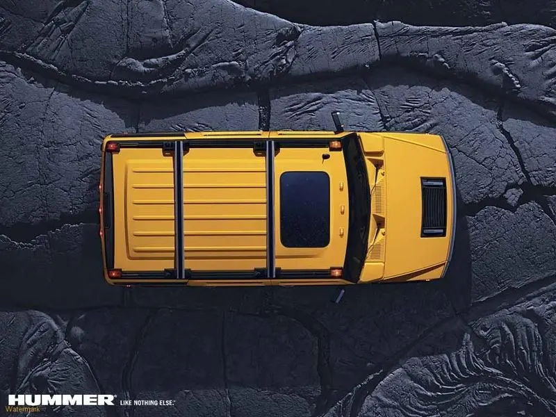
What are types of roofs in modern automotive world:
In later years, many variations on the automobile roof developed. These include:
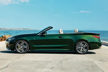
- Convertible roofs:
- Hardtops
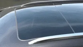
- Sunroofs
- T-tops
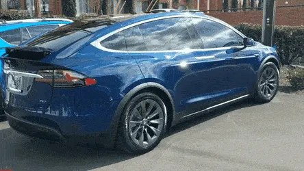
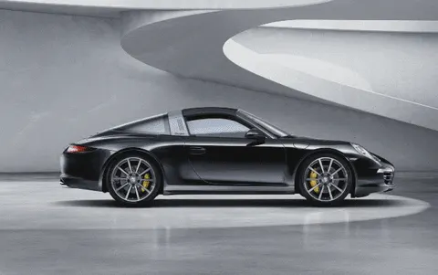
- Targa tops
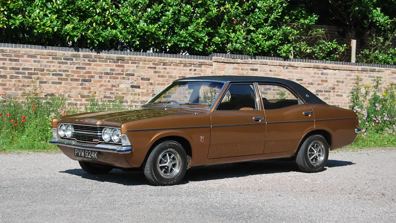
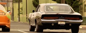
- Vinyl roofs
Design considerations:
- Visibility criteria
- Head room criteria
- Heat distortion and snow load
- Material thickness
Material properties:
Material: Steel
Thickness:0.75mm
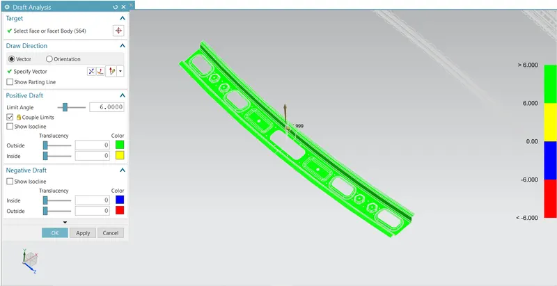
Draft angle for steel 7 degrees (minimum)
Required process to join is spot welding
What is roof crush analysis:
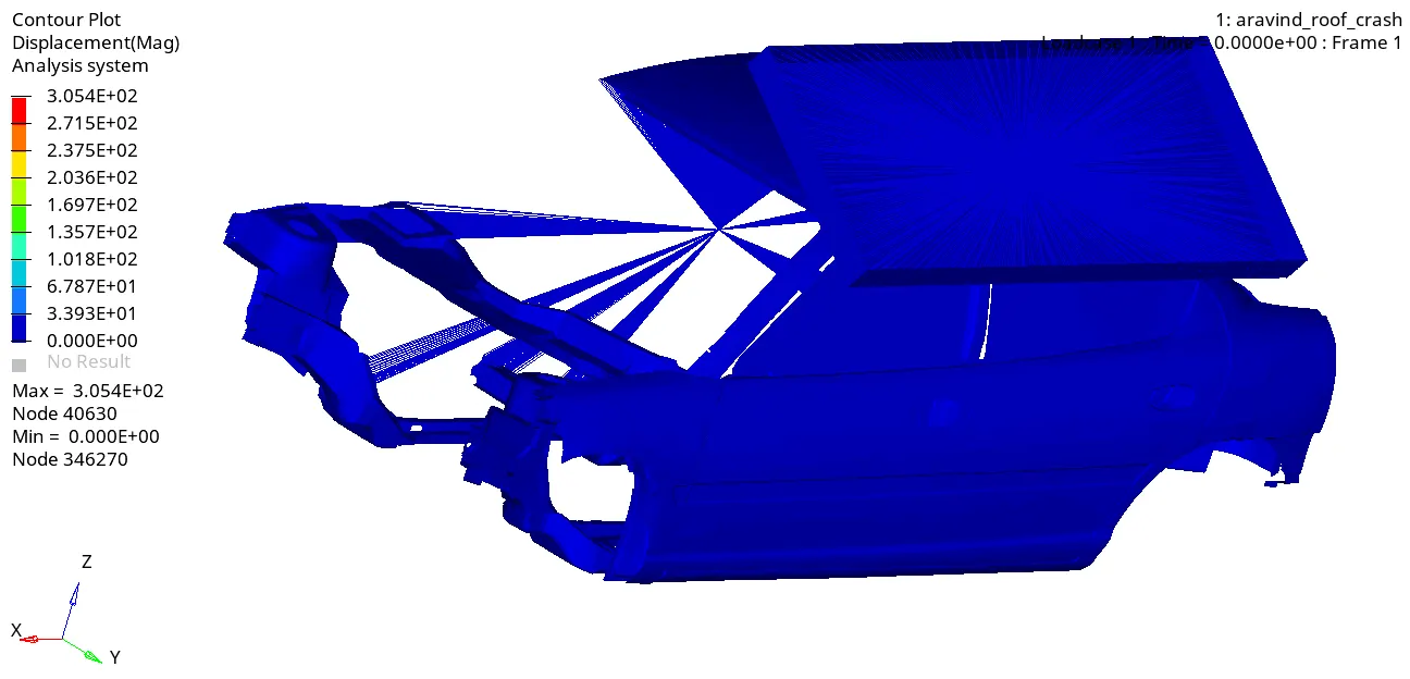
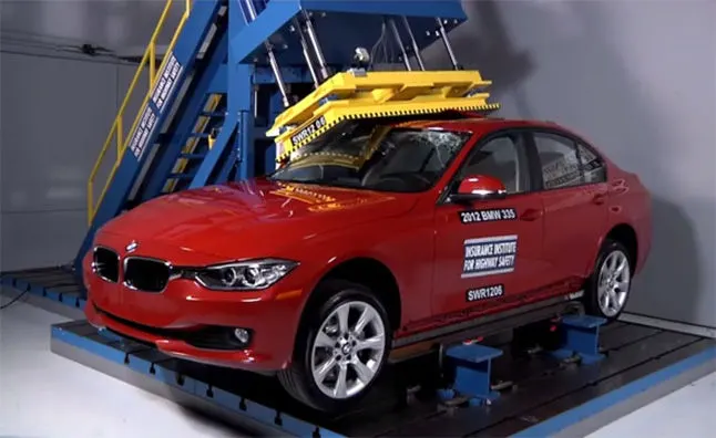
One of the tests used in occupant safety analysis is a roof crush test. It is used to evaluate how a car will deform during a rollover accident. A safer car does not deform as much providing the occupant a larger survival space during this kind of accident. In this test, a plate shaped impactor is pushed down on one side of the roof at constant (slow, quasi-static) speed. This load case challenges the solver because of large deformations, complex contact situations as well as local buckling. This model was computed successfully with the LS-DYNA R9.0.1 MPP implicit solver including dynamic effects. Last but not least, we want to acknowledge the CCSA for the baseline model.
Components of roof:
Front roof rail:
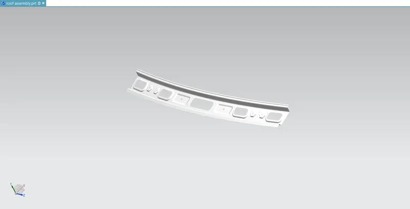
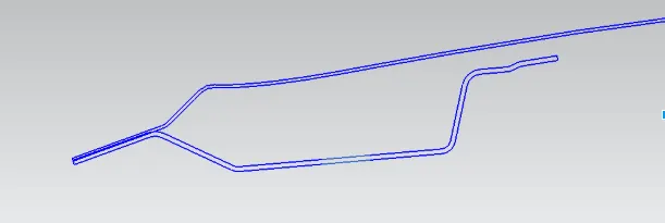
Front roof rail is one of the parts which joining the roof outer and wind shield then the inner panel as well and we need to consider the head room clearance of driver and visibility of driver and notably this one’s manufacturing from body side outer scrap materials, it's where all the other features such as irvm and reading lamp, sun glass holder going to get mounted.
Master section of front roof rail:
Bow roof 1:
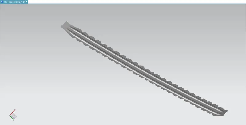
Bow roof is one of component that providing the additional support to the roof typically we use the bow roofs as I meant before and the number of itself can be varied each of vehicle's respect to the length of roof of itself.
Center reinforcement:
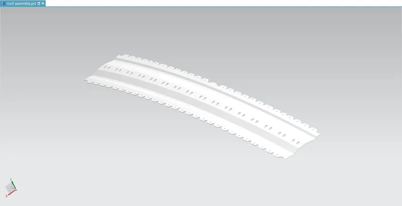
As we’d looked at bow roof 1 this one is also giving extra support for the roof and center roof rail there’s a reason behind adding this, we can only see this at sunroof variants since in order to create a sunroof we’ll have to reduce the material on that particular region so that’s why we’re providing reinforcement on center roof rail by spot welding or mastics.
Center roof rail:
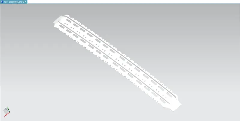
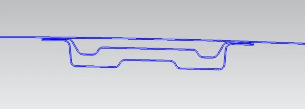
This one’s also a known as one of the stiffening components but not only like so it does can be also a cross member of both side of the vehicle this is also joined at both ends of body side by either spot welding or mastics.
Master section of center roof rail and reinforcements:
Bow roof 2:
This one’s also providing the support to the roof same as bow roof one and whatever I've mentioned about the bow roof 1 that everything will similar to the bow roof 2 Aswell.
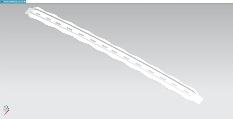
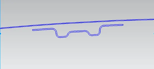
Master section of the bow roof 1 and 2:
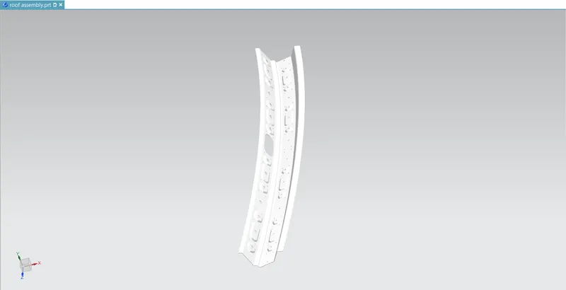
Rear roof rail:
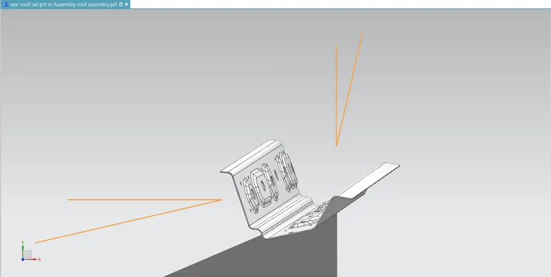
Rear roof rail is the part which joining the back door and roof as together and inner panel as well then, I've gave some embosses to make this component as stronger.
Heat distortion calculation:
Bow–roof prediction Formula
W = [1.73 x 10^(-3) x L] + [1.85 x 10^(-8) x (R^2)/t] + [ 1.10x10^(-3) x l] - 2.68
Judgement Condition: OK< 2.7> 3.1
Where
L = Roof Length in X-Direction[mm] (Roof dimension in 0-Y)
R = Roof curvature
R = 2(Rx*Ry)/(Rx+Ry)
Rx = X curvature
Ry = Y curvature
t = Roof plate thickness [mm]
l = Bow Roof Span [mm]
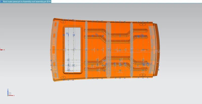
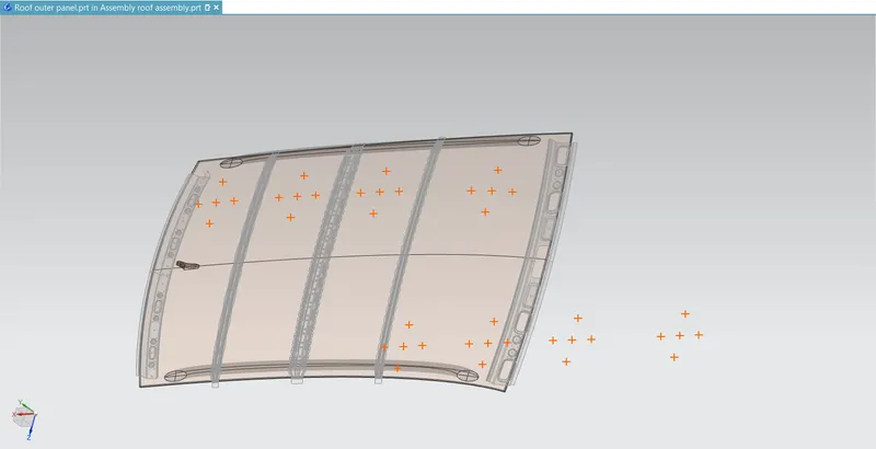
In this case I am going to left the points between front roof rail and bow roof 1 because I've got the sunroof over there so, let’s do study between the other points, so that let’s begin the calculation from bow roof 1 and center roof rail.
Position no 1:
Bow roof 1 and center roof rail
Rx = 4467.95mm
Ry= 7368.15mm
L= 2033.73mm
R= 2(Rx*Ry)/(Rx+Ry)
Hence, R= 5563.178mm
I=359.8mm
R^2/t= 41265265.95mm
So, W = [1.73 x 10^ (-3) x L] + [1.85 x 10^ (-8) x (R^2)/t] + [ 1.10x10^ (-3) x l] - 2.68
“W= 1.99”
Position no 2: center roof rail and bow roof 2
Rx = 49855.66mm
Ry= 2902.09mm
L= 2033.73mm
R= 2(Rx*Ry)/(Rx+Ry)
Hence, R= 5484.904
I=370.2mm
R^2/t= 40112229.19mm
So, W = [1.73 x 10^ (-3) x L] + [1.85 x 10^ (-8) x (R^2)/t] + [ 1.10x10^ (-3) x l] - 2.68
“W= 1.98”
Position no 3: Bow roof 2and rear roof rail
Rx = 3380.48mm
Ry=3186.74mm
L= 2033.73mm
R= 2(Rx*Ry)/(Rx+Ry)
Hence, R= 3280.752mm
I =345.7mm
R^2/t= 14351111.58mm
So, W = [1.73 x 10^ (-3) x L] + [1.85 x 10^ (-8) x (R^2)/t] + [ 1.10x10^ (-3) x l] - 2.68
“W= 1.48”
| POSITION OF BOWS: | Rx(mm) | Ry(mm) | R(mm) | I(mm) | L(mm) | R^2/t(mm) | T(mm) | W | OK/NG |
| BRR1 AND CRR | 4467.95 | 7368.15 | 5563.178 | 359.8 | 2033.73 | 41265265.95 | 0.75 | 1.99 | OK |
| CRR AND BRR2 | 49855.66 | 2902.09 | 5484.904 | 370.2 | 2033.73 | 40112229.19 | 0.75 | 1.98 | OK |
| BRR2 AND RRR | 3380.48 | 3186.74 | 3280.752 | 345.7 | 2033.73 | 14351111.58 | 0.75 | 1.48 | OK |
Snow load criteria:
Snow load Prediction formula
Qr = [Iy x t2] / [α x s x [(Rx + Ry)/2]2 x 10-8]
Where
α = My x Lx2 x 10-12 , My = Y(Ly-Y)
Judgement condition = Qr ≥ 3.1
250 ≤ s ≤ 380
t = Roof plate thickness [mm]
Ly = Distance between the front and rear roof Rails on the Vehicle along with 0Y[mm]
Length of Roof panel with the center point between Roof rail Front /Rear as the front and rear reference point.
Lx = Distance between the Left and Right end of the roof on the Roof BOW [mm]
Width of the roof panel exposed on the surface.
Y = Distance front Front Roof Rail to Roof BOW [mm]
s = Distance for which Roof BOW bears divided load [mm]
s = L1/2 + L2/2
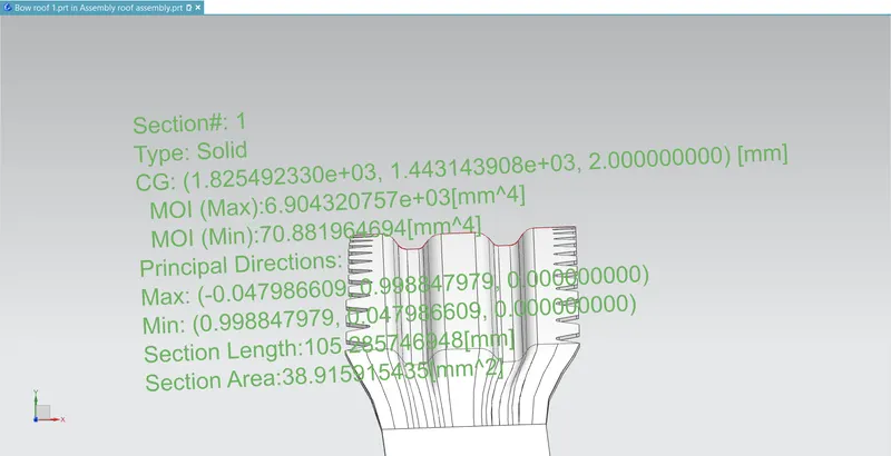
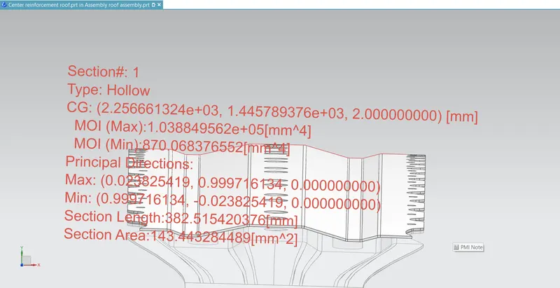
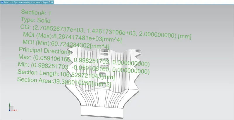
Iy = Geometrical moment of inertia of Roof BOW (Y cross-section) [mm4]
Rx = Lateral direction curvature radius of roof panel Y cross-section on Roof BOW [mm]
Roof panel curvature Radius of the Length Lx in Front view
Ry = Longitudinal Direction curvature radius of the Roof panel X cross-section on Roof BOW [mm]
Roof panel X curvature radius of length s in Side view
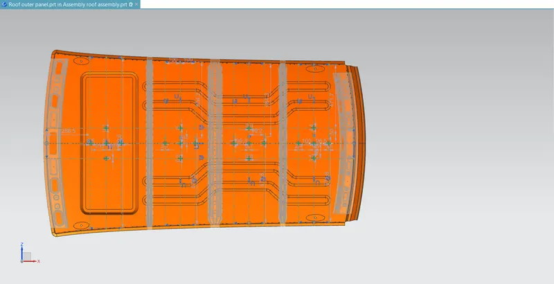
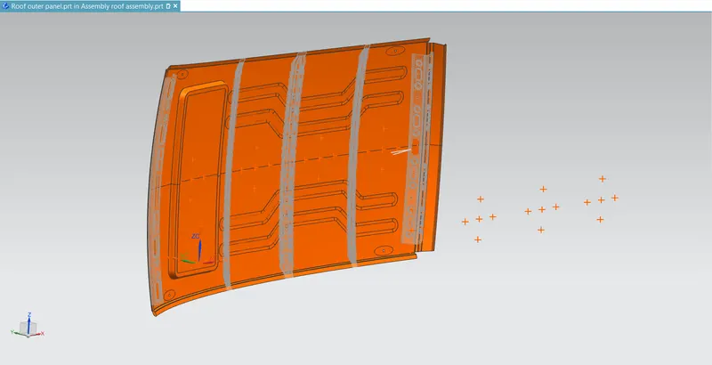
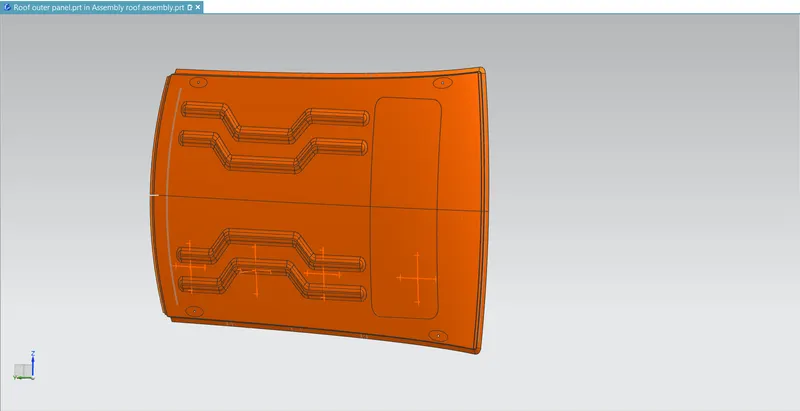
Position no 1:
Front roof rail and bow roof 1
Rx= 4094.74mm
Ry= 3299.25mm
Lx = 1123.6mm
Ly = 2033.73 mm
Y= 567.92 mm
Iy= -
S = 645mm
My = 832462.81
α = My x Lx2 x 10-12 so, α = 1.05
t = 0.75 mm
Qr = [Iy x t2] / [α x s x [(Rx + Ry)/2]2 x 10-8]
Qr = -
Position no 2:
bow roof 1 and center roof rail
Rx= 3851.04mm
Ry= 5700.65mm
Lx = 1079.46 mm
Ly = 2033.73 mm
Y= 432.8 mm
Iy= 8700.68 mm^4
S = 433.5mm
My = 692882.504
α = My x Lx2 x 10-12 so, α = 0.80
t = 0.75 mm
Qr = [Iy x t2] / [α x s x [(Rx + Ry)/2]2 x 10-8]
Qr= 61.872
Position no 3:
Center roof rail and bow roof 2
Rx= 2521.83mm
Ry= 4113.36mm
Lx = 1058.6 mm
Ly = 2033.73 mm
Y= 448.9 mm
Iy= 6072.42 mm^4
S = 450 mm
My = 711430.18
α = My x Lx2 x 10-12 so, α = 0.79
t = 0.75 mm
Qr = [Iy x t2] / [α x s x [(Rx + Ry)/2]2 x 10-8]
Qr= 87.296
Position no 4:
Bow roof 2 and rear roof rail
Rx= 3915.97mm
Ry= 16810.37 mm
Lx = 1046.2mm
Ly = 2033.73 mm
Y= 370.3mm
Iy= -
S = -
My = 615968.12
α = My x Lx2 x 10-12 so, α = 0.67
t = 0.75 mm
Qr= -
| POSITOIN OF THE BOWS: | Rx(mm) | Ry(mm) | Lx(mm) | Ly(mm) | Y(mm) | Iy(mm^4) | S(mm) | My | α t(mm) Qr OK/NG |
| BRR 1 AND CRR | 3851.04 | 5700.65 | 1079.46 | 2033.73 | 432.8 | 8700.68 | 433.5 | 692882.504 | 0.80 0.75 61.872 OK |
| CRR AND BRR 2 | 2521.83 | 4113.36 | 1058.6 | 2033.73 | 448.9 | 6072.42 | 450 | 711430.18 | 0.79 0.75 87.296 OK |
| BRR2 AND RRR | 3915.97 | 16810.37 | 1046.2 | 2033.73 | 370.3 | - | - | 615968.12 | 0.67 0.75 - NEGLIGIBLE |
Geometric moment of inertia:
Bow roof: 1
Center roof rail:
Bow roof 2:
Draft analysis:
Front roof rail:
Bow roof 1:
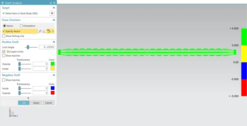
Bow roof 2:
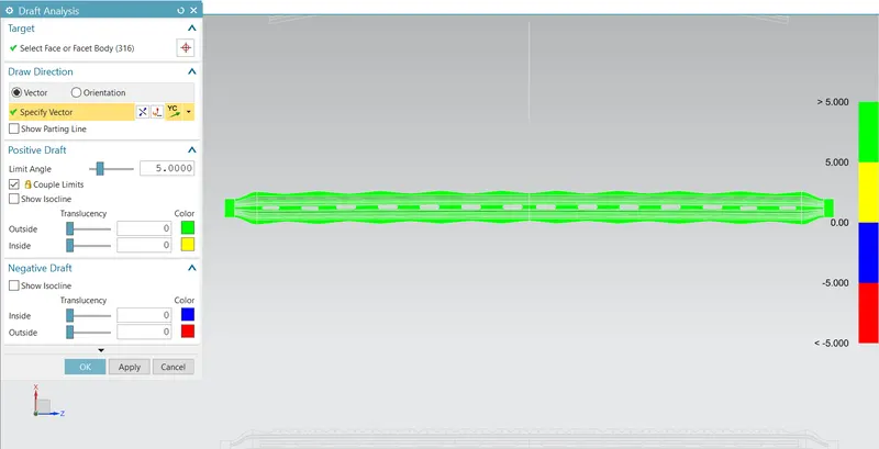
Center reinforcement:
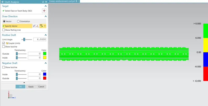
Center roof rail:
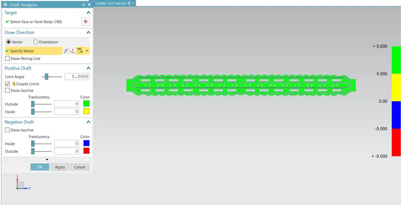
Rear roof rail:
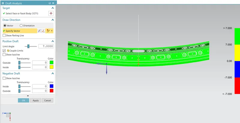
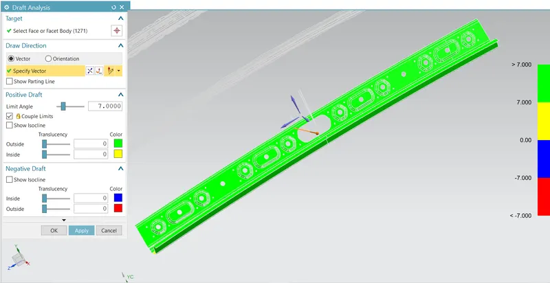
So, in this case I've take the couple of tooling directions from the top and from the side of itself because in this case we have some complicated design of embosses we can’t create it by single tool in single operation so I’ve separated the parts as two and give them couple of tools to get this produced, mostly we will look how to reduce the number of tool and tooling direction for save time and cost but in some cases we’d better have multiple tools and the tooling directions as well for quality reasons.
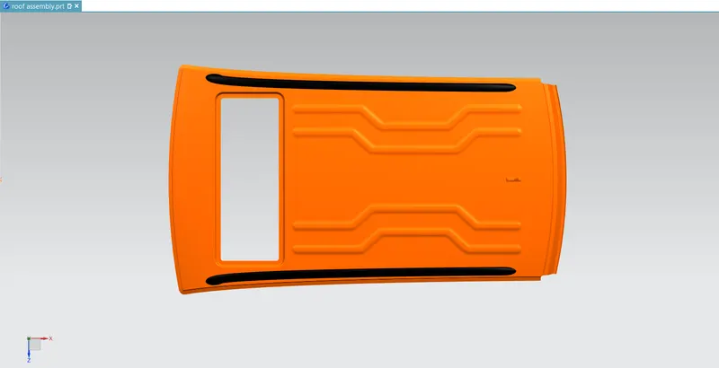
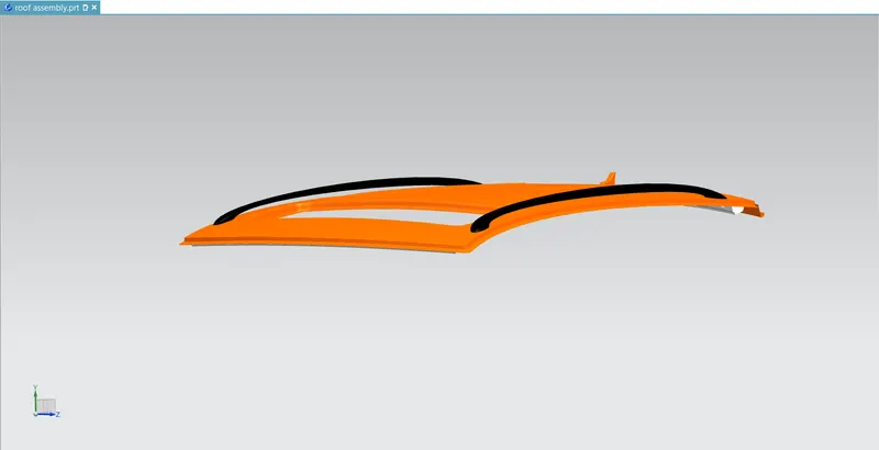
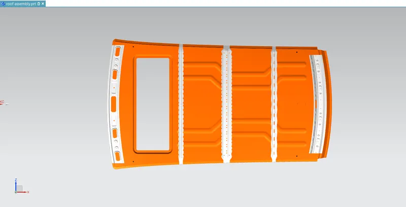
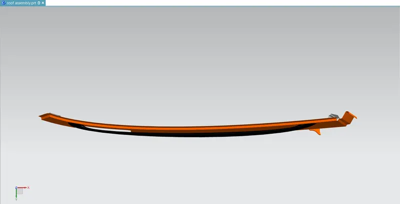
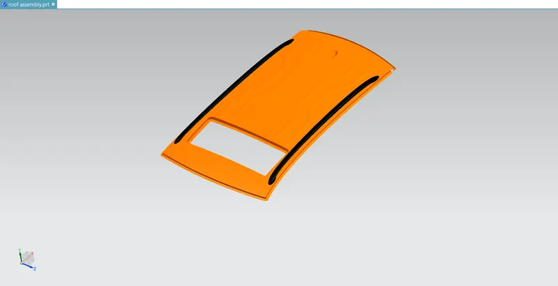
Assembled views of my roof:
CONCLUSSION:
I've designed my roof with required flanges and as per the requirements of oem as well then roof is not as what we are seeing from out side by working on this assignment i've learnt plenty of things about design the roof.