Roof challenge
ROOF DESIGN:
INTRODUCTION:
An automobile roof is the portion of an automobile that sits above the passenger compartment, protecting the vehicle occupants from sun, wind, rain, and other external elements. Though it just looks like a styling surface that protects from sun, wind and other elements, various environmental conditions are taken into account for designing of the same.
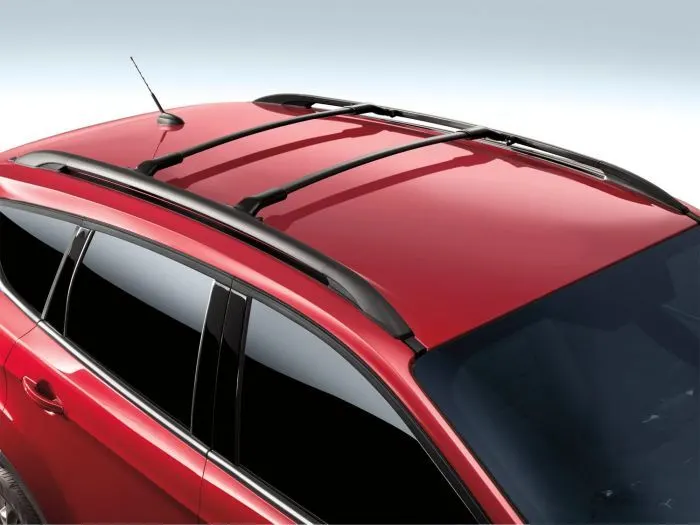
Roof should be provided with proper reinforcements for strengthening. Vehicle roof can be subjected to high heat conditions or load during snowy conditions. To make the roof withstand these conditions, various calculations are done. This ensures the safety of the passengers in the vehicle.
Types of reinforcements
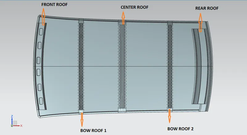
- front roof rail
- bow roofs
- central roof rail
- rear roof rail
OBJECTIVE:
- For the the given styling surface Perform a curvature study on the roof
- perform the calculations for the heat distortion and snow load criteria to determine whether the bow roofs are at the correct positions.
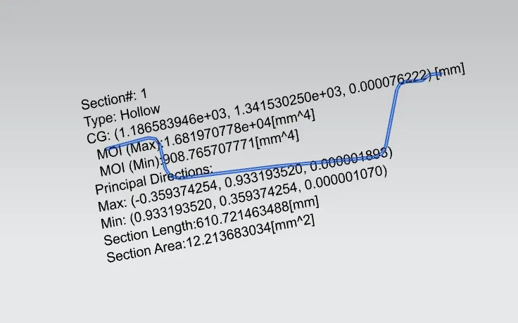
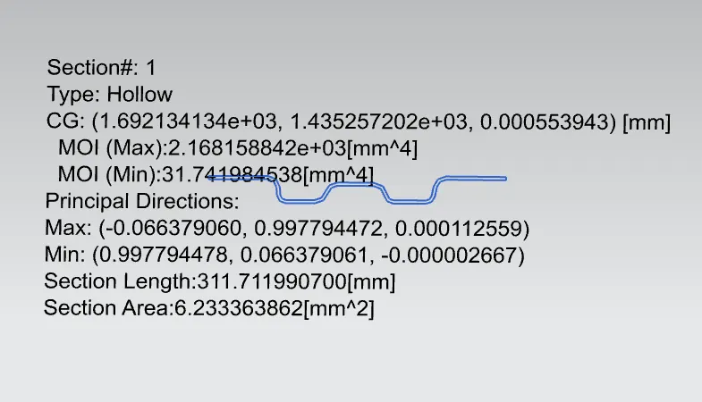
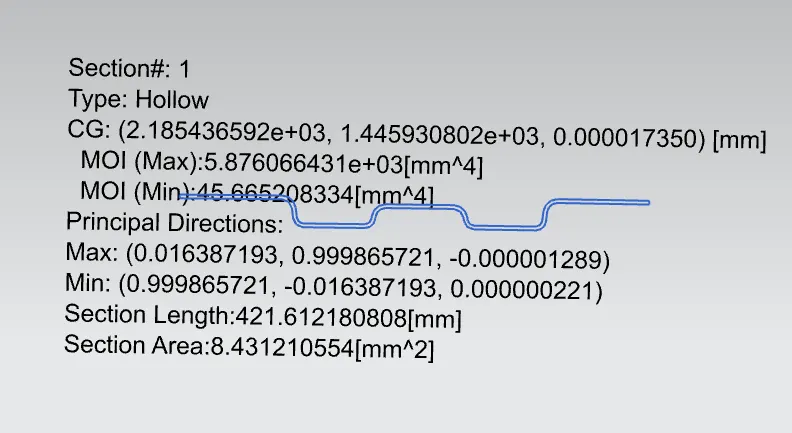
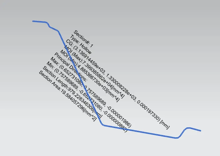
- Finding moment of inertia and section modulus for Bow roofs , central roof rail,front roof rail and rear roof rail
- Perform the draft analysis for each reinforcements.
DESIGN:
FRONT ROOF RAIL:
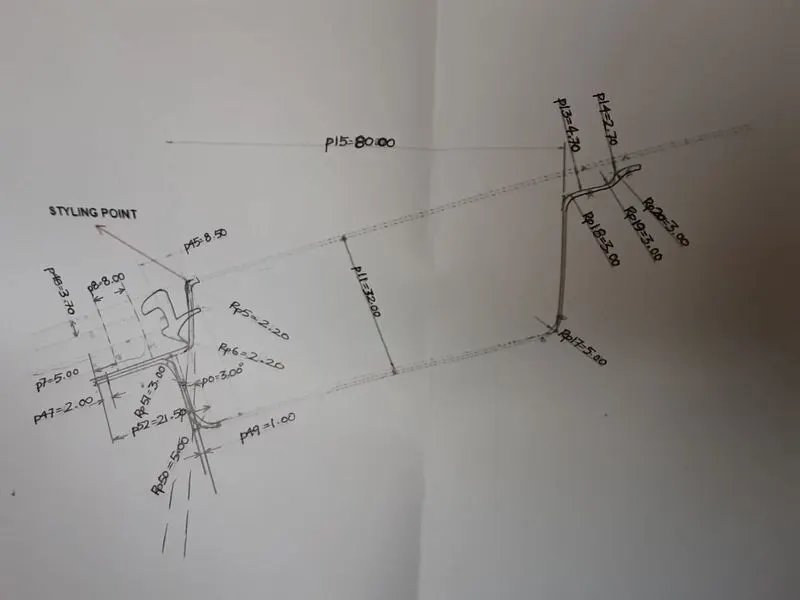
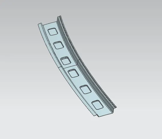
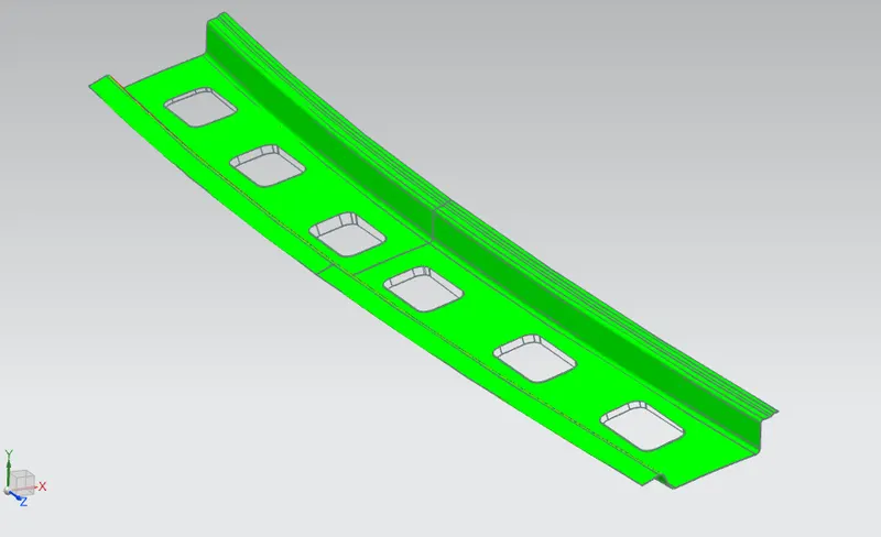
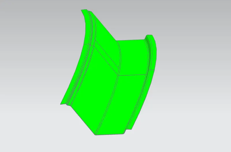
Front roof is joined with the Wind Shield Glass, Body Side Outer and the inner panels.the thickness of the rail is 0.75 mm.we are going to use draft angle in between 5-7 degrees. The Wind Shield end flange is the exact offset of the roof surface. This part is joined to the BIW body and windshield. Visibility criteria is taken in account for joining it with the windshield. It is fixed to BIW with spot welds and the roof surface is attached with the help of mastic sealants. A draft angle is provided for deep drawing operation.At the end of design use draft analysis to ensure the given angle is correct or not if not clear the angle position and check.
MASTERSECTION
FRONT ROOF DESIGN
DRAFT ANALYSIS
BOW ROOF RAIL:
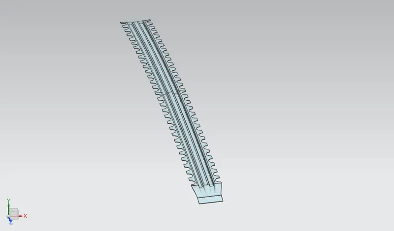
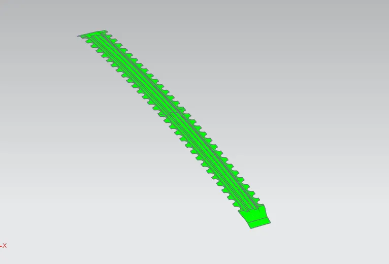
The bow roofs are given to improve the strenght, torsional stiffness and load bearing capacity of the roof.The number of bow roofs present depends on the overall size of the roof.If sunroof present at the top of the roof means we going to use only one bow roof alone.the bow roof placing is depend upon the shape and length of the roof.
DESIGN
DRAFT
CENTER ROOF:
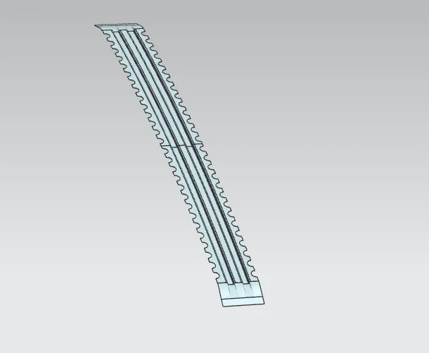
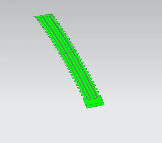
The central roof rail is placed at the center of the roof which is connected to the B-pillar support structure.This central roof rail helps in adding the strength to the roof during the roll- over test.Spot Welds are not applied for joining these rails to the roof.Instead of spot weld we use Mastic sealent to join the center bow roof with the roof.here we apply thickness for the roof is 0.75 mm.
DESIGN
DRAFT
REAR ROOF RAIL:
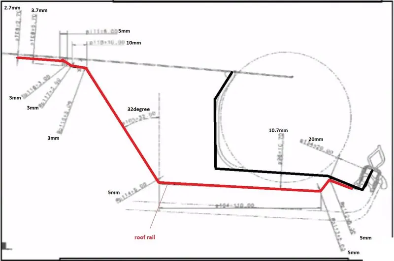
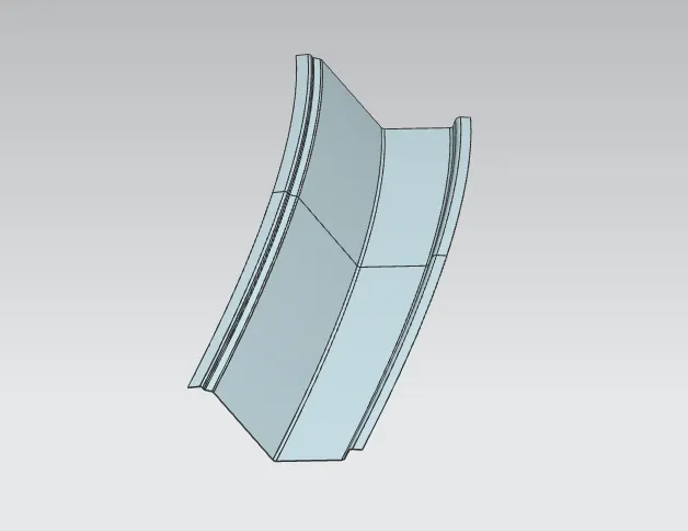
In rear roof we joint back door and body side panels and here we use both mastic and weld for joining.
MASTERSECTION
DESIGN
DRAFT
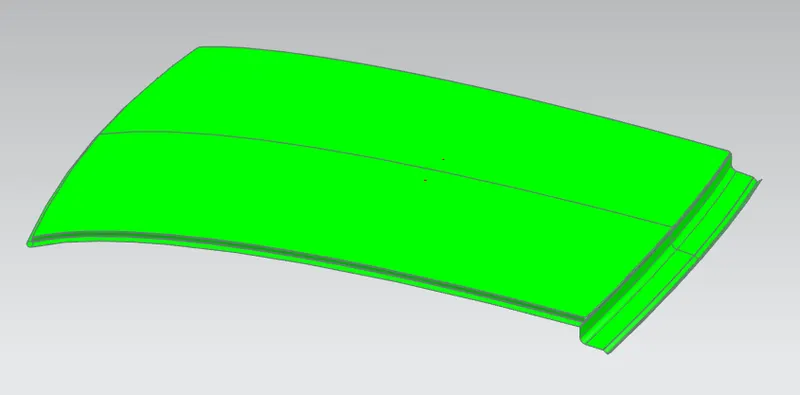
DRAFT ANALYSIS FOR OUTER PANELS:
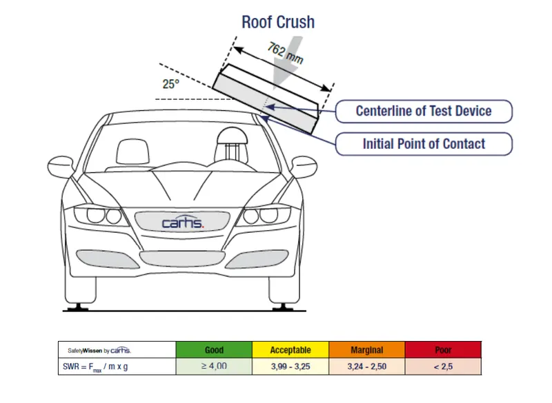
CRASH TEST:

CALCULATION:
HEAT DISTORTION CALCULATION:
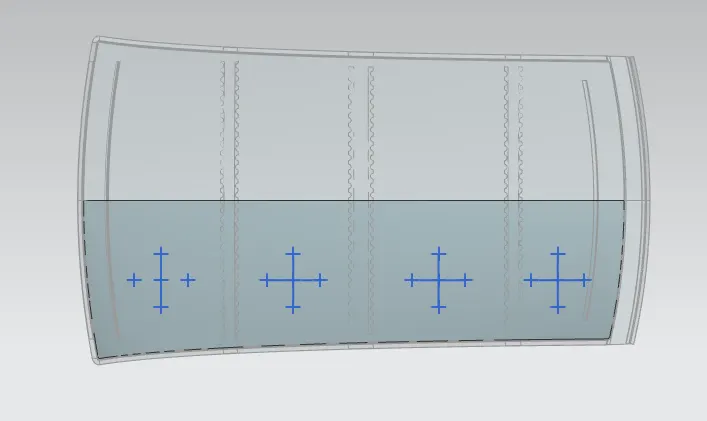
This study is done to check how the sheet metal components perform in the extreme heat conditions. Sheet metals have a tendency to change their shape in high temperatures.. This study is used to predict the heat distortion temperature at where the material starts to soften when exposed to a fixed load at elevated temperature.In order to avoid bending or damaging the roof, based on the heat distortion temperature , this study will predict the bow roof position which helps to strengthen the roof .
Bow–roof prediction Formula
W = [1.73 x 10^(-3) x L] + [1.85 x 10^(-8) x (R^2)/t] + [ 1.10x10^(-3) x l] - 2.68
Judgement Condition : OK< 2.7> 3.1
Where
L = Roof Length in X-Direction[mm](Roof dimension in 0-Y)
R = Roof curvature
R = 2(Rx*Ry)/(Rx+Ry)
Rx = X curvature
Ry = Y curvature
t = Roof plate thickness [mm]
l = Bow Roof Span [mm]

SNOW LOAD CRITERIA:
Snow load Prediction formula
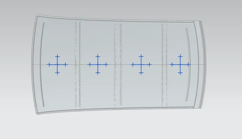
Qr = [Iy x t2] / [α x s x [(Rx + Ry)/2]2 x 10-8]
Note: The Qr value given over here is correct. There was a typo error in the formula given in the video.
Where
α = My x Lx2 x 10-12 , My = Y(Ly-Y)
Judgement condition = Qr ≥ 3.1
250 ≤ s ≤ 380
t = Roof plate thickness [mm]
Ly = Distance between the front and rear roof Rails on the Vehicle along with 0Y[mm]
Length of Roof panel with the center point between Roof rail Front /Rear as the front and rear reference point.
Lx = Distance between the Left and Right end of the roof on the Roof BOW [mm]
Width of the roof panel exposed on the surface.
Y = Distance front Front Roof Rail to Roof BOW[mm]
s = Distance for which Roof BOW bears divided load [mm]
s = L1/2 + L2/2
Iy = Geometrical moment of inertia of Roof BOW (Y cross-section )[mm4]
Rx = Lateral direction curvature radius of roof panel Y cross-section on Roof BOW [mm]
Roof panel curvature Radius of the Length Lx in Front view
Ry = Longitudinal Direction curvature radius of the Roof panel X cross-section on Roof BOW [mm]
Roof panel X curvature radius of length s in Side view

SECTION INERTIA :
S = I / y
where :
S= Section modulus
I = second moment of inertia (or area moment of inertia, not to be confused with moment of inertia)
y = the distance from the neutral axis to any given fibre. It is often reported using y = c, where c is the distance from the neutral axis to the most extreme fibre