Roof challenge
AIM : To design and develop car roof by given roof styling,master sections. Calculate the Bow-roof position by making roof curvature study.
OBJECTIVE:
- Introduction
- To develop the all componets by using styling & Master section.
- To calculate the Bow-roof position by making roof curvature study.
- To calculate the heat distortion criteria of the cars roof.
- To calculate the section modulus of all roof components.
- To determine the snow load criteria for car roof.
- To perfarm the draft analysis of all roof components.
Software used
NX CAD-12.
Introduction
An automobile roof or car top is the portion of on automobile that sits above the passenger compartment, protecting the vehicle occupants from sun, wind, rain, and other external elements.
Basically we look out side is styling surface based on that we can develop the all inner componets like front foof rail, rear roof rail and bow roof as well reinforcements. They are attached with ditch area.
A sun roof is a moveable panel that opens to uncover a window in an automobile roof, allowing light and fresh air to passenger compartment.
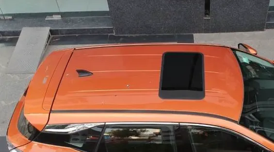
Fig 1, Roof.
Developing Roof Components.
- Outer Roof
Outer Roof is styling surface which having 0.75mm thickness. The outer roof having connected with ditch area that will help to attach the BIW components with help of robotic spot welding. While developing dicth area some parameters are play important role which are headroom clearance, visibility criteria, clearance for wind shield and Back door are some of factors to be considered while designing the ditch area. Below fig 2 & 2.1 shown styling surface and developed outer roof with ditch area.
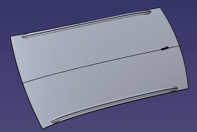
Fig 2 styling surface.
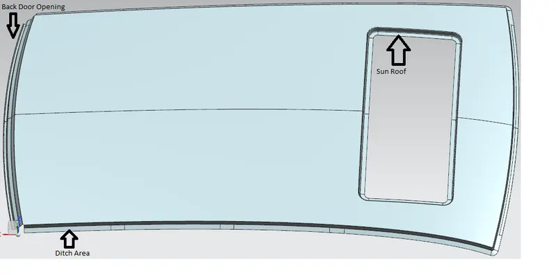
Fig 2.1 Developed Outer Roof.
- Front Roof Rail.
Below fig 2.2 shown front roof rail master section. Basically we can develop the front roof rail with help of master section. while preparing the master section we can consider the main parameters like Headroom clearane, visibility criteria. Front roof rail attached to ditch area with help of spot welding. having an thickness 0.75mm. Mastics are placed at which having maintened gap between the outer roof and front roof rail. Thus it was increase the srength of componens.
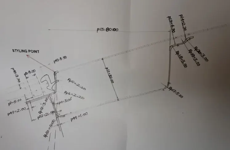
Fig 2.2 Front Roof Rail Master section.
Below fig 2.3 shown fornt roof rail.
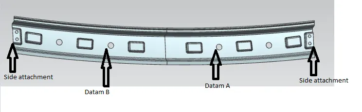
The above fig 2.3 which having shown A,B Datams. This are fuction like check points after component manufacturing. This similar datams are considered in fixtures. Fixtures are help to check the physical component. The major check points are in fixture are GAP and FLUSH. Side attachments are given to joint with the A Pillar attachments.
Below fig 2.4 shown side view and Top view.
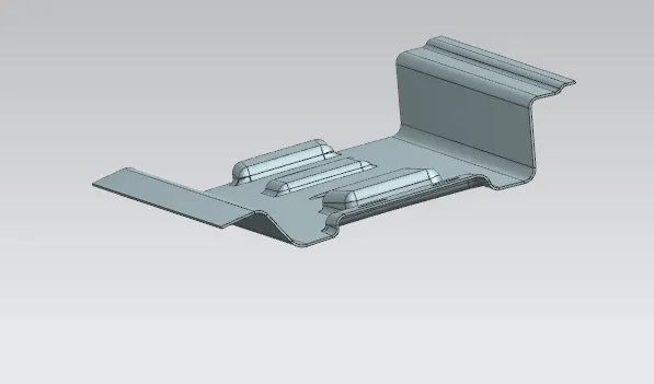
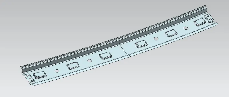
Fig 2.4 Side and Top view.
- Reinforcement
The main function of reinforcement is provide the strength to Bow Roof. Bow roof is placed on it attached with help of spot welding. In this design i was maintained 1.2mm thickness and widthh of 80mm. While preparing the reinforce ment at least have maintain 5mm gap from the outer roof. That should be help to place the mastics. End of the reinforcement are attached with ditch area. Below fig 2.5 shown the reinforcement.

Fig 2.5 Top View.
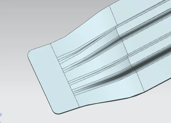
Fig 2.5 End joints with help of Guide curves and studio surface.
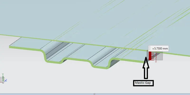
Fig 2.5 Cutting Section View.
- Bow Roof 1.
Bow roof 1 is placed on reinforcement. Mastics are placed on bow roof 1. Mastics are helps as Supporting member of outer roof. Bow roof 1 having an thickness of 0.75mm and width of 60mm. Below fig 2.6 shown
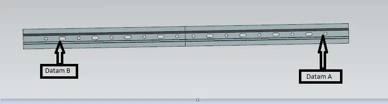
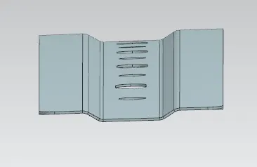
Fig 2.6 Bow Roof 1.
The above fig shown datam which will function like check points.
- Bow Roof 2 & 3.
Bow roof 2,3 are basically look same but curvature changes depends upon roof styling. Below fig 2.7 shown Bow roof 2 & 3.
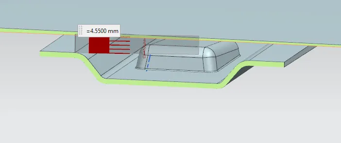
Fig 2.7 Bow Roof 2 &3.
Both bow Roof Given 1.2mm Thickness and width 60mm.
- Rear Roof Rail.
Rear Roof Rail is similar to front roof rail. Having on thickness of 0.75 and width of 125mm.Below fig 2.8 shown master section and Rear Roof Rail.
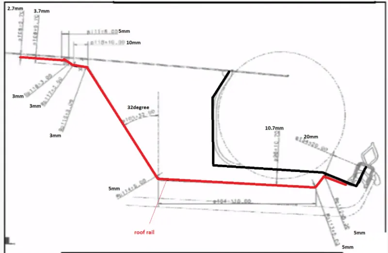
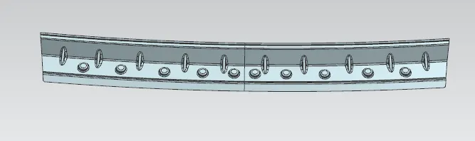
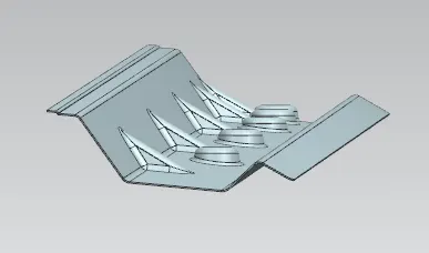
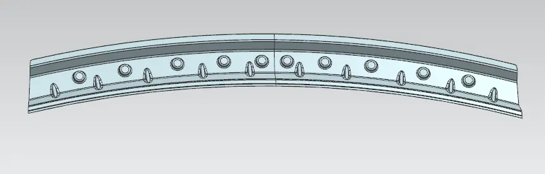
Fig 2.8 Rear Roof Master Section and Rear Roof Design.
After creating the all sloid components Now have to calculate the heat distortion. Formla for heat distorsion given below. That will help to Bow–roof prediction.
W = [1.73 x 10^(-3) x L] + [1.85 x 10^(-8) x (R^2)/t] + [ 1.10x10^(-3) x l] - 2.68
Judgement Condition : OK< 2.7> 3.1
Where
L = Roof Length in X-Direction[mm](Roof dimension in 0-Y)
R = Roof curvature
R = 2(Rx*Ry)/(Rx+Ry)
Rx = X curvature
Ry = Y curvature
t = Roof plate thickness [mm]
l = Bow Roof Span [mm]
For calculations requried all dimensions are find out with help of ploting the sketches on outer roof curvature. All dimensions are shown below fig.
- Create a line at the center of the roof part in the O-Y axis and then draw another line with a distance of 300mm to the O-Y line.
- Now create lines at a distance of 100mm on both sides to the 300mm line.
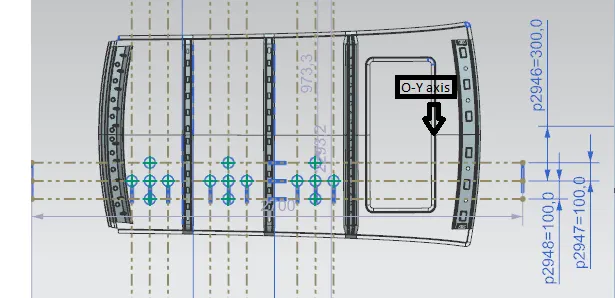
- Create a new lines in X direction between the bow roofs and rail roofs.
- Using these center line create lines at a distance of 100mm on both sides.
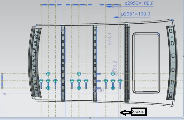
- Now intersect (lines in Y-direction) and (lines in X-direction). This result will give us some points where the lines are coinciding each other.
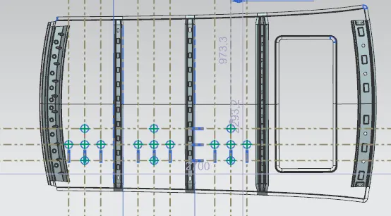
- Extract the requried points and project them on the roof surface. Now using these points create a 3 point arc or circle and note the radius of the arc in the X direction as Rx and in the Y direction as Ry.
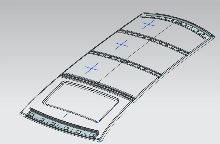
Since we got all requried values now put in to the given formula.
W = [1.73 x 10^(-3) x L] + [1.85 x 10^(-8) x (R^2)/t] + [ 1.10x10^(-3) x l] - 2.68.

Note : All dimensions are in mm.
Judgement Condition : OK< 2.7> 3.1
Below fig shown all components.
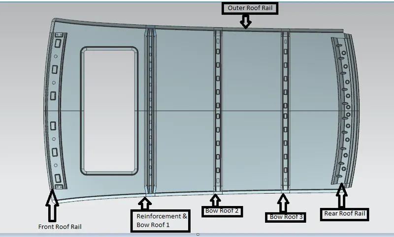
Note: Since there is a sunroof in between the front roof rail and bow roof 1. The heat distortion criteria will not be calculated for that area.
Calculating the snow load criteria.
Snow load Prediction formula
Qr = [Iy x t2] / [α x s x [(Rx + Ry)/2]2 x 10-8]
Note: The Qr value given over here is correct. There was a typo error in the formula given in the video.
Where
α = My x Lx2 x 10-12 , My = Y(Ly-Y)
Judgement condition = Qr ≥ 3.1
250 ≤ s ≤ 380
t = Roof plate thickness [mm]
Ly = Distance between the front and rear roof Rails on the Vehicle along with 0Y[mm]
Length of Roof panel with the center point between Roof rail Front /Rear as the front and rear reference point.
Lx = Distance between the Left and Right end of the roof on the Roof BOW [mm]
Width of the roof panel exposed on the surface.
Y = Distance front Front Roof Rail to Roof BOW[mm]
s = Distance for which Roof BOW bears divided load [mm]
s = L1/2 + L2/2
Iy = Geometrical moment of inertia of Roof BOW (Y cross-section )[mm4]
Rx = Lateral direction curvature radius of roof panel Y cross-section on Roof BOW [mm]
Roof panel curvature Radius of the Length Lx in Front view
Ry = Longitudinal Direction curvature radius of the Roof panel X cross-section on Roof BOW [mm]
Roof panel X curvature radius of length s in Side view.
Steps to follow for calculating the values.
- Create a line at the center of the roof part in the O-Y axis.
- Now using this O-Y line as a centre create lines with a distance of 100mm on both sides.
- Now Create lines in X direction by centre of components and then draw 2 lines with 100mm distance from centre line.
- Create a points by using of inter section lines. Then points are to be project on outer roof surface.
- Then create 3 point circle with help of points. Which will help us to find out Rx,Ry. Below fig shown all parameters.
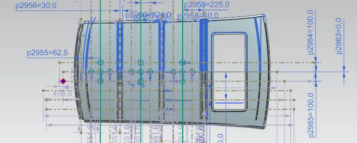
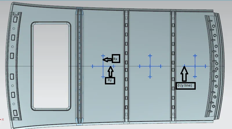
Now calculate the snow load criteria.

Note : There is no snow load criteria in bow roof 3 and and rear roof due L2 not available.
Section Modulus.
Section Modulus of Bow Roof 1.
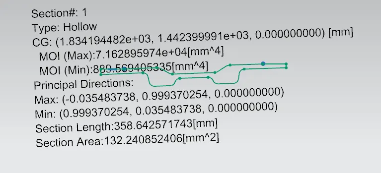
S=((I)/(Y)).
I=889.56mm4, Y=40mm
S=22.23mm3.
Section Modulus of Bow Roof 2.
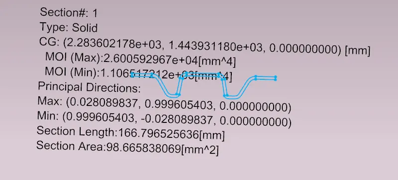
I=1106.517mm4, Y:30mm.
S=36.8839mm3.
Section Modulus of Bow Roof 3.
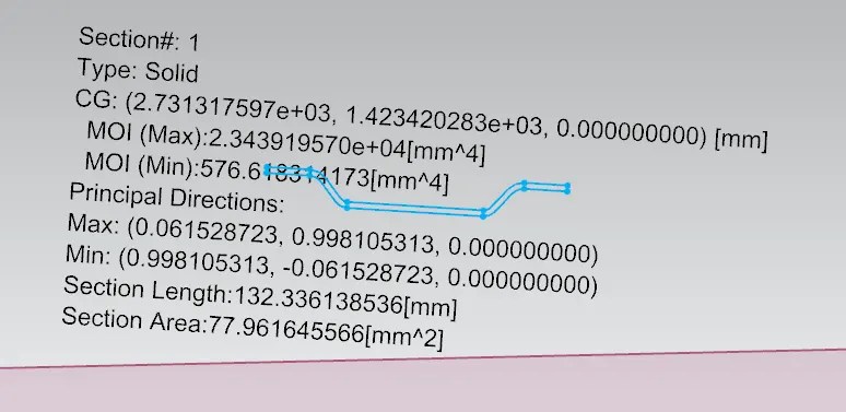
I=576.618mm4, Y=30mm.
S=19.22mm3.
Draft Analysis.
Draft Analysis of Outer Roof.
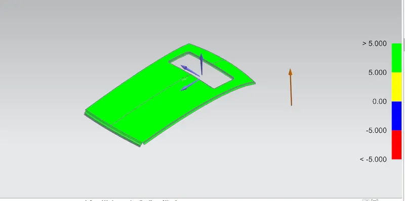
Draft Analysis of Front Roof Rail.
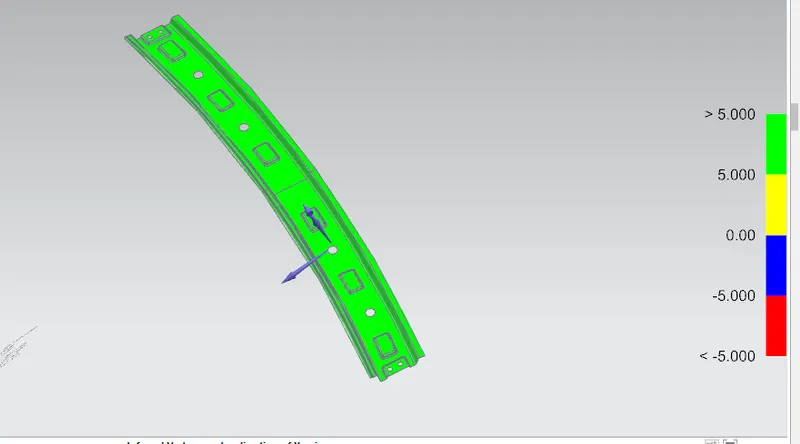
Draft Analysis of Bow Roof 1.
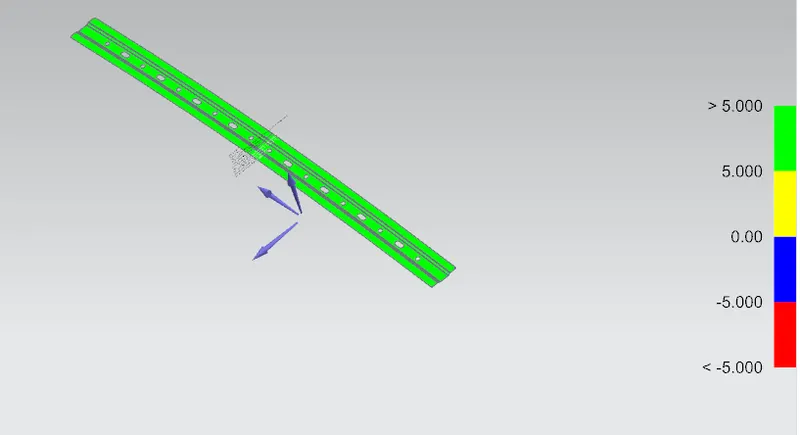
Draft Analysis of Bow Roof 2.
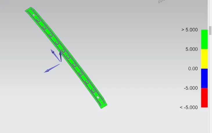
Draft Analysis of Bow Roof 3.
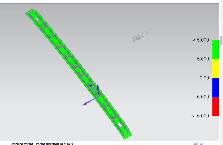
Draft Analysis of Reinfocement.
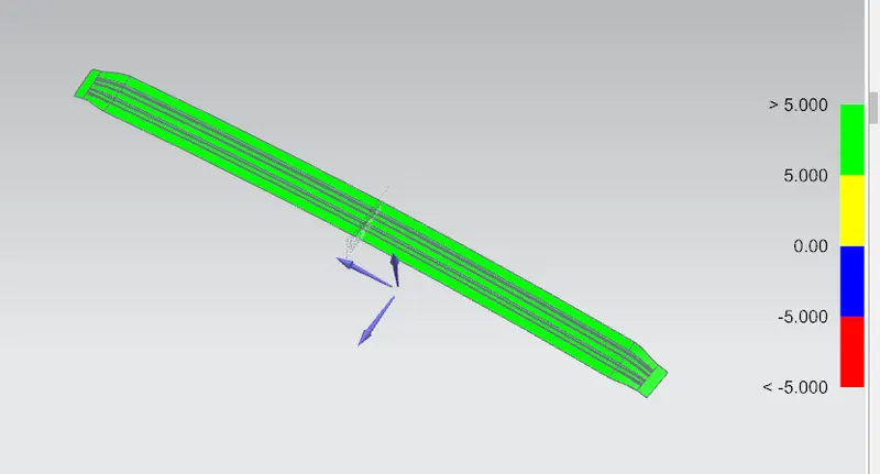
Draft Analysis of Rear Roof Rail.
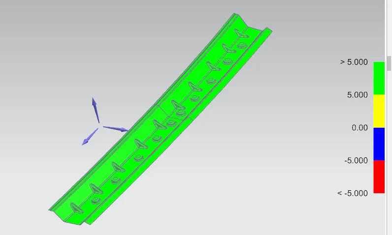
The above fig shown draft analysis of all components are found positive draft at 5 degree and feasible to manufacturing.
Conclusion.
The roof all components are design as per master section and design consideration. Roof curvature study helps to place the bow roof positions to pass the heat distortion and snow load load criteria. Once proto part is manufactured then Roof crush test will conduct with help of physical part. Rest of roof crush test all prediction are acceptable.