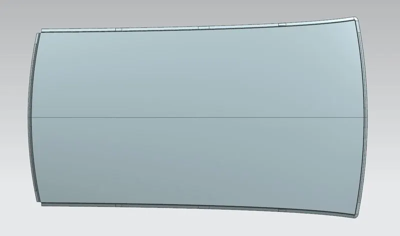
Roof challenge
Designing Of Car Roof
An automobile roof or car top is the portion of an automobile that sits above the passenger compartment, protecting the vehicle occupants from sun, wind, rain, and other external elements.
Different Types Of Car Roofs :
- Hardtop: A hardtopis a rigid form of automobile roof, which for modern cars is typically constructed from metal. A hardtop roof can be either fixed (i.e. not removable), detachable for separate storing or retraceable within the vehicle itself.
- Sunroof: A sunroofis a movable panel that opens to uncover a window in an automobile roof, allowing light and fresh air to enter the passenger compartment. Sunroofs can be manually operated or motor driven, and are available in many shapes, sizes and styles.
- Convertible: A convertibleor cabriolet is a passenger car that can be driven with or without a roof in place. The methods of retracting and storing the roof vary between models. A convertible allows an open-air driving experience, with the ability to provide a roof when required. Potential drawbacks of convertibles are reduced structural rigidity.
Tools and features used in designing of car roof
- Law of extension: Law of Extension creates flanges or extensions when a particular direction is important or when it is necessary to reference the existing face.
- Embossing: Emboss command use to create an embossing by modify a body with faces made by projecting a section along a vector, with options for end cap location and shape.
- Trim Sheet: Trim sheetcommand use to trim off a portion of a sheet body using curves, faces, or datum planes.
- Bridge curve: The bridge curvesare perpendicular to the surface edge at the intersection point
- Face Blend: Face Blendis primarily used to blend between faces of separate bodies. It can also be used to blend between faces of a single body.
- Through curve mesh: Through Curve Mesh command is used to create a body through a mesh of sections in one direction, and guides in another direction, where the shape fits through the mesh of curves. This command uses sets of primary curves and sets of cross curves to create a bi-cubic surface. Each set of curves must be contiguous.
Various processes involved in car roof manufacturing are:
- Blanking: It is a metal fabrication process, in which a metal work piece is removed from the primary metal strip or sheet when it is punched. The material that is removed is used as new metal work piece or blank.
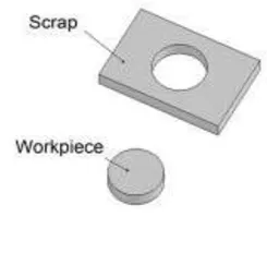
- Drawing: Deep drawingis a sheet metal forming process in which a sheet metal blank is radially drawn into a forming die by the mechanical action of a punch. It is thus a shape transformation process with material retention. The process is considered "deep" drawing when the depth of the drawn part exceeds its diameter.
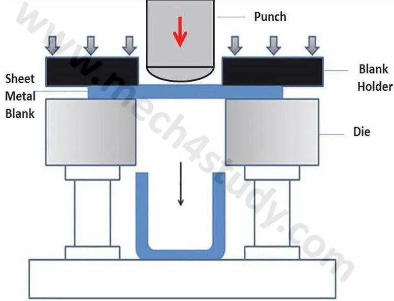
- Piercing: It is a shearing process, here raw material pierced with a machining tool, resulting in the creation of hole.
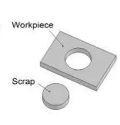
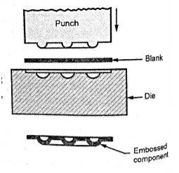
- Embossing: It is a stamping process for producing raised or sunken designs or relief in sheet metal.
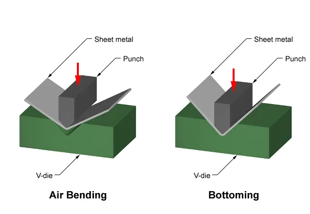
- Bending: Bendingis a manufacturing process that produces a V-shape, U-shape, or channel shape along a straight axis in sheet metal.
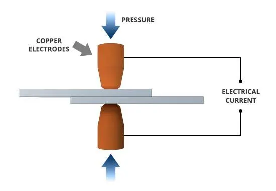
- Spot welding: Spot welding is a resistance welding process. This welding process is used primarily for welding two or more metal sheets together by applying pressure and heat from an electric current to the weld area.
Parts required for car roof assembly are
- Roof Outer Panel
- Front Roof Rail
- Rear Roof Rail
- Bow Roof Rails

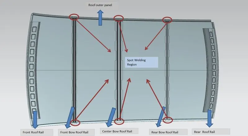
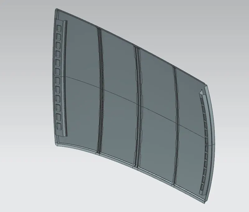
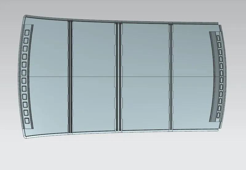
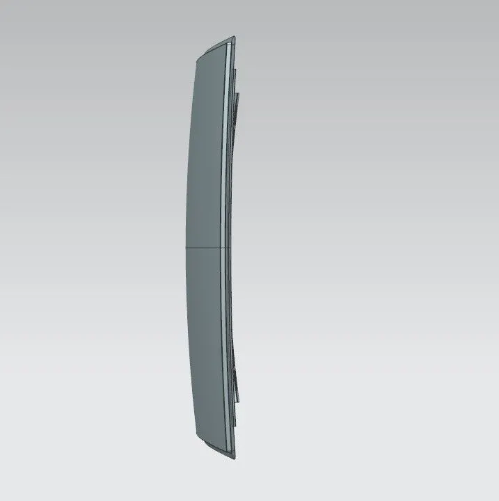
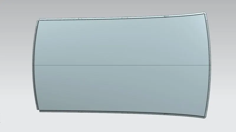
Roof Outer Panel: Roof Outer Panel is the styling surface which sits above the passenger compartment, protecting the vehicle occupants from sun, wind, rain, and other external elements.
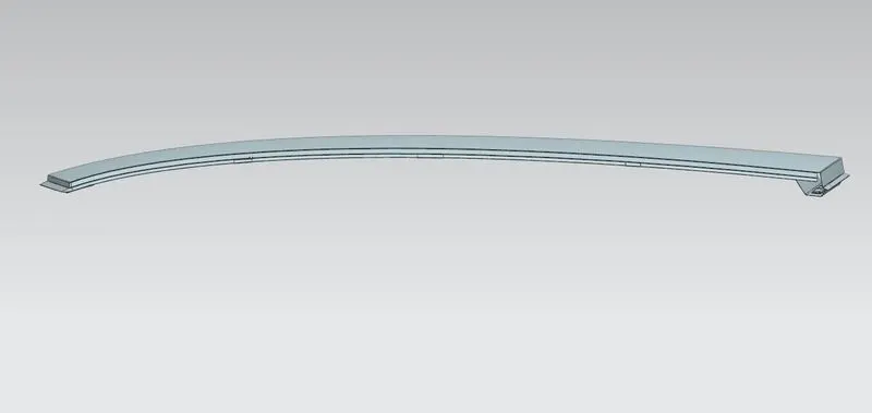
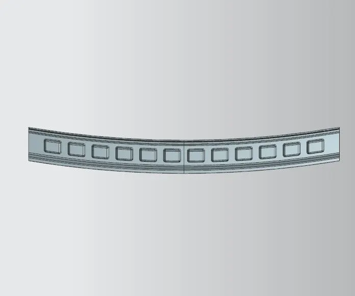
Front Roof Rail: Front roof rail is the reinforcement for the roof outer panel and it joins with the windshield glass, front roof rail is joined with roof outer panel using mastic sealant.
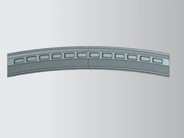
Rear Roof Rail: Rear roof rail is the reinforcement for the roof outer panel and it joins with the back door, rear roof rail is joined with roof outer panel using mastic sealant.
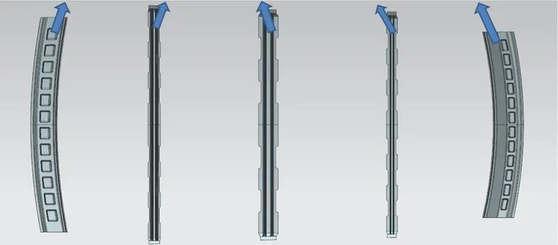
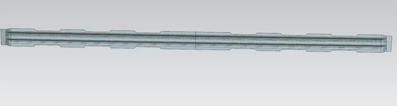
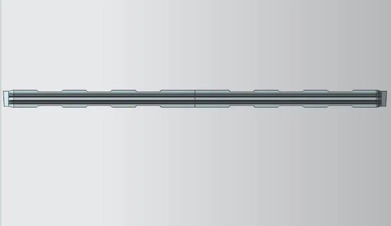
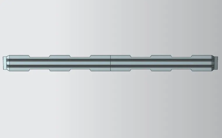
Bow Roof Rails: Bow roof rails are also acts as the reinforcement for the roof outer panel and it joins with the body side, bow roof rail is joined with roof outer panel using mastic sealant and spot welded with body side.
Front Bow Roof Rail:
Rear Bow Roof Rail:
Center Bow Roof Rail:
Design Methodology for Car Roof Rails.
- Master Section
- Mastic Sealant Application
- Draft Analysis
- Section Inertia Study
- Roof Curvature Study
- Heat Distortion Criteria
- Snow load Acceptance Criteria
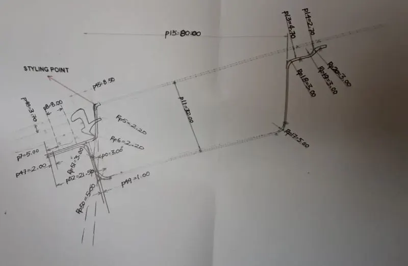
Master Section: It is a 2D representation of profile showing roof outer panel and roof rails. This includes details about how roof outer panel and roof rails are held together, and the required dimensions to design the roof rails.
Master Section For Front Roof Rail:
Master Section For Rear Roof Rail:
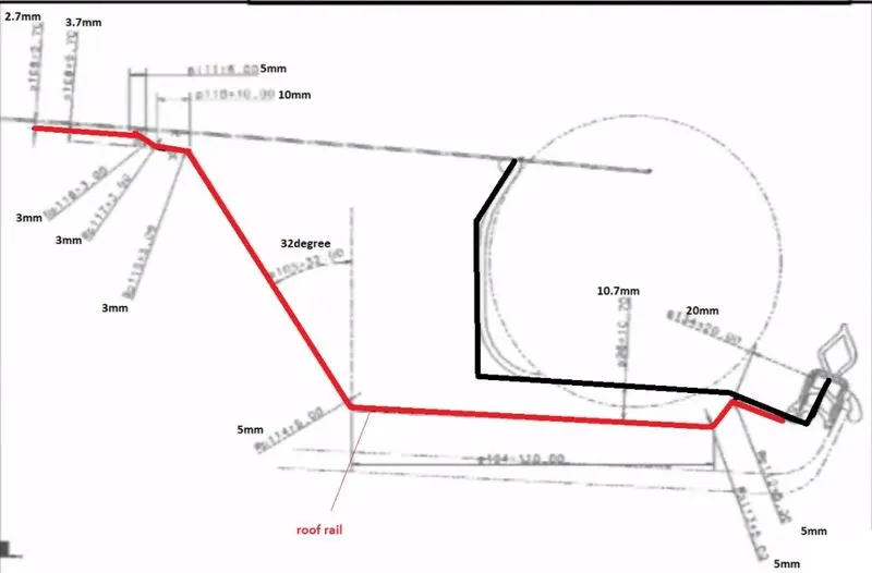
Mastic Sealant Application: These sealants glues the roof outer panel with the roof rails, After subjecting these sealants to heat, it solidifies to form a strong bond between the roof outer panel and roof rails, these sealants avoid fluttering during high speed and minimises the NVH.
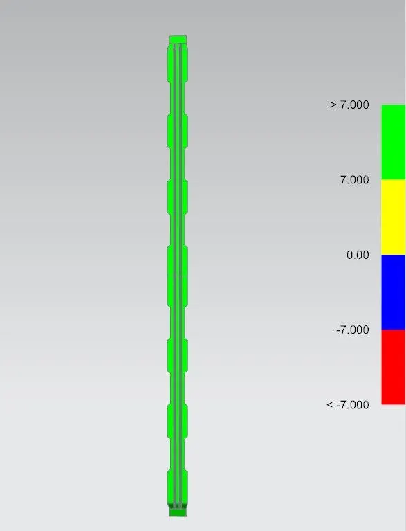
Draft Analysis: Draft Analysis allows to verify whether the product will be easily removed from the mould, or if need to correct the draft to facilitate mould release.
Draft Analysis For Front Roof Rail:
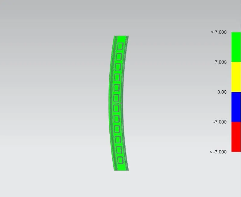
Draft Analysis For Rear Roof Rail:
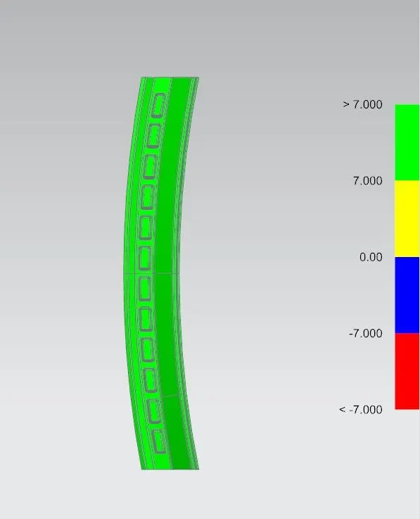
Draft Analysis For Front Bow Roof Rail:
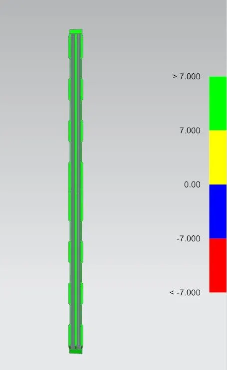
Draft Analysis For Center Bow Roof Rail:
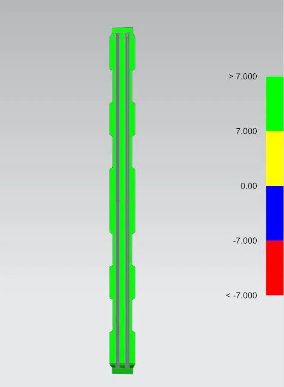
Draft Analysis For Rear Bow Roof Rail:
Section modulus Study: Section modulus is termed as the ratio of second moment of area and distance from N.A (Neutral axis) to the extreme end of the object. Also it is the measure of strength of given member. The stress in the outermost section of beam is computed with the help of section modulus. It is indicated by “S”.
S=I/Y
Here, I is “moment of inertia” and Y is distance from “neutral axis” to extreme end of the object
Unit of a “section modulus” is (mm3).
Section modulus Study For Front Roof Rail:
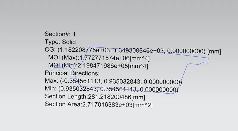
I max= 1.772×106 mm4
I min= 2.198×105 mm4
Y= 120.64 mm
S max= I max/Y
S max= 14,671 mm3
S min= I min/Y
S min= 1,821 mm3
Section modulus Study For Rear Roof Rail:
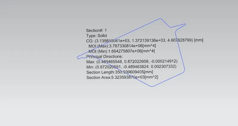
I max= 3.767×106 mm4
I min= 1.664×106 mm4
Y= 137.805 mm
S max= I max/Y
S max= 27,335 mm3
S min= I min/Y
S min= 12,075 mm3
Section modulus Study For Front Bow Roof Rail:
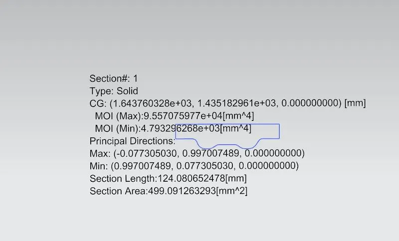
I max= 9.557×104 mm4
I min= 4.793×103 mm4
Y= 52 mm
S max= I max/Y
S max= 1,837 mm3
S min= I min/Y
S min= 92.173 mm3
Section modulus Study For Center Bow Roof Rail:
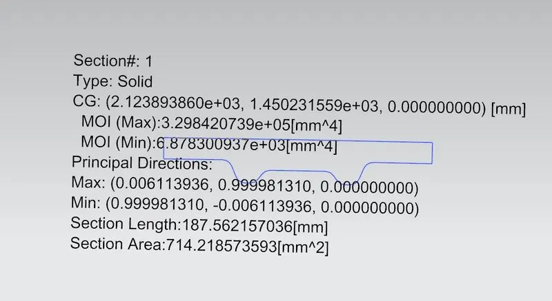
I max= 3.298×105 mm4
I min= 6.878×103 mm4
Y= 82 mm
S max= I max/Y
S max= 4,021 mm3
S min= I min/Y
S min= 83.878 mm3
Section modulus Study For Rear Bow Roof Rail:
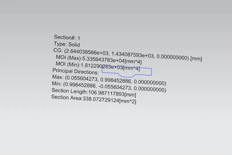
I max= 5.335×104 mm4
I min= 1.812×103 mm4
Y= 46 mm
S max= I max/Y
S max= 1,159 mm3
S min= I min/Y
S min= 39.39 mm3
Roof Curvature Study:
Heat Distortion Criteria:
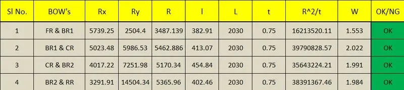
W= [1.73 × 10⁻³× L] + [1.85×10⁻⁸× (R2/t] + [1.10×10⁻³× l] – 2.68
Judgement Condition: OK < 2.7
Where,
L = Roof Length in X- Direction [mm] (Roof dimension in 0 – Y)
R = Roof Curvature
R = 2(Rx*Ry) / (Rx+Ry)
Rx = X curvature
Ry = Y curvature
t = Roof plate thickness [mm]
l = Bow roof span [mm]
Snow load Acceptance Criteria:
Qr = [Iy × t2] / [α × s × [(Rx + Ry)/2]2× 10-8]
Judgement Condition = Qr ≥ 3.1
250 ≤ s ≤ 380
Where,
α = My × Lx^ (2) × 10^ (-12)
My = Y(Ly – Y)
t = Roof Plate Thickness [mm]
Ly = Distance between the front and rear roof rails on the vehicle along with OY [mm]
Lx = Distance between the left and right end of the roof on the roof bow [mm]
Y = Distance from front roof rail to roof bow [mm]
s = Distance for which roof bow bears divided load [mm]
s = L1/2 + L2/2
Iy = Geometrical moment of inertia of roof bow (Y cross-section) [mm⁴]
Rx = Lateral direction curvature radius of roof panel Y cross-section on roof bow [mm]
Ry = Longitudinal direction curvature radius of the roof panel X cross-section on roof bow [mm]

Car Roof Final Assembly: