Roof challenge
ROOF DESIGN
OBJECTIVE :
- The objective of this project is to design car roof with essential flanges and reinforcements like ditch area , front roof rail , bow roofs, central roof rail and rear roof rail for the the given styling surface
- Perform a curvature study on the roof and perform the calculations for the heat distortion and snow load criteria to determine whether the bow roofs are at the correct positions.
- Finding moment of inertia and section modulus for Bow roofs , central roof rail . front roof rail and rear roof rail .
- Perform the draft analysis for each reinforcements
SOFTWARE USED :
NX -CAD
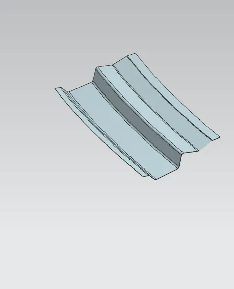
FRONT ROOF RAIL:
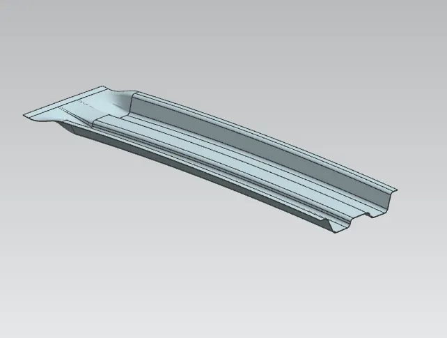
BOW ROOF 1:
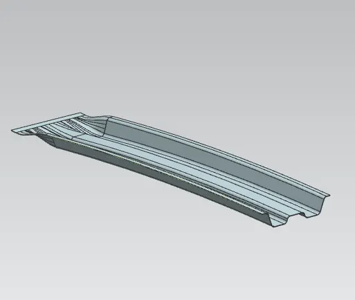
BOW ROOF 2:
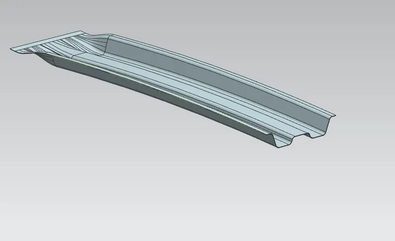
CENTER BOW ROOF:
REAR ROOF RAIL:
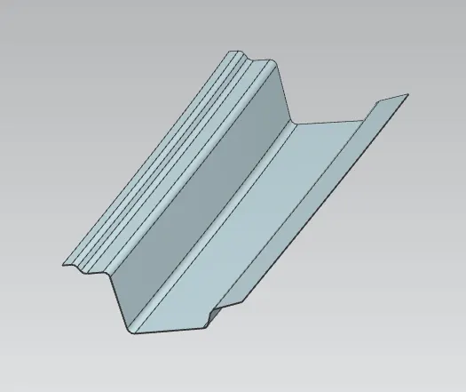
CAR ROOF DESIGN:
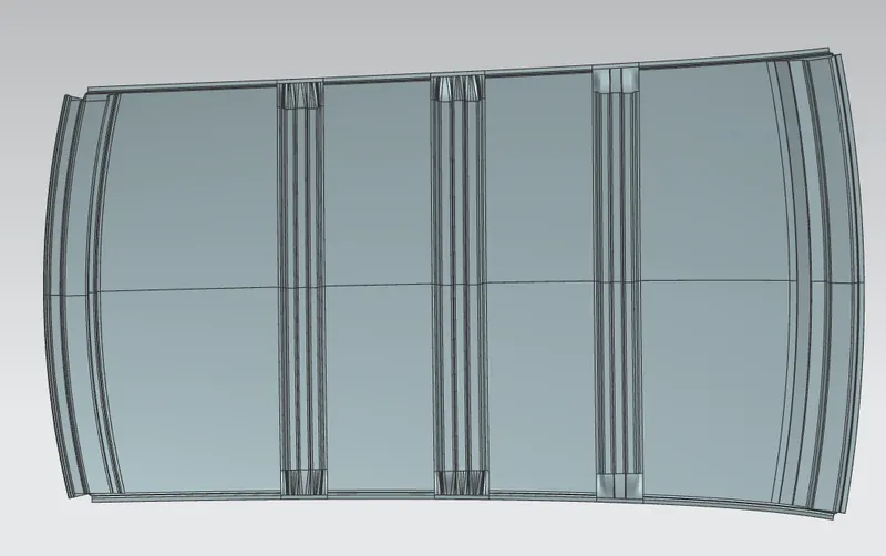
HEAT DISTORTION STUDY ON THE ROOF :
Bow – roof prediction Formula
W = [1.73 x 10^(-3) x L] + [1.85 x 10^(-8) x (R^2)/t] + [ 1.10x10^(-3) x l] - 2.68
Where
L = Roof Length in X-Direction[mm](Roof dimension in 0-Y)
R = Roof curvature
R = 2(Rx*Ry)/(Rx+Ry)
Rx = X curvature
Ry = Y curvature
t = Roof plate thickness [mm]
l = Bow Roof Span [mm]
Judgement Condition : OK< 2.7> 3.1
|
S No |
BOWs |
Rx |
Ry |
R |
l |
L |
t |
W |
OK/NG |
|
1. |
Frt & 1st |
5589 |
2650 |
3595 |
220 |
2034 |
0.7 |
1.42 |
OK |
|
2. |
1st & CTR |
4852 |
3220 |
3871 |
378 |
2034 |
0.7 |
1.65 |
OK |
|
3. |
Center & 2nd |
4070 |
4130 |
4099.8 |
290.5 |
2034 |
0.7 |
1.60 |
OK |
|
4. |
2nd & Rear |
3418 |
4776 |
3984 |
278 |
2034 |
0.7 |
1.56 |
OK |
SNOWED CRITERIA:
Formula to be used,
(Prediction Formula) Qr =(ly⋅t)2∝⋅s⋅{Rx+Ry2}2⋅108=(ly⋅t)2∝⋅s⋅{Rx+Ry2}2⋅108
Where α=My*Lx2*10-12 [ My = Y(Ly-Y)]
Here,
t = Roof plate thickness [mm]
Ly = Dist. Between the front & rear rails on 0Y [mm]
Lx = Dist. Between the left & right roof ends [mm]
Y = Dist. Between the front & rail center [mm]
s =(L1/L2)+(L2/2) (all in mm)
from the data available we got Y=480mm, t=0.7
Snowed criteria prediction Qr was found to be Good [PASS]
[as per judgement condition Qr: OK ≥ 3.1mm & 250 ≤ S ≤ 380]
|
S No |
BOWs |
ly |
Lx |
Ly |
Y |
α |
s |
Rx |
Ry |
t |
Qr |
OK/NG |
|
1. |
Frt & 1st |
2213 |
1127 |
2034 |
480 |
0.95 |
256 |
1389 |
2921 |
0.7 |
0.96 |
OK |
|
2. |
1st & CTR |
2479 |
1089 |
2034 |
480 |
0.88 |
251 |
2662 |
6234 |
0.7 |
2.26 |
OK |
|
3. |
Center & 2nd |
4068 |
1066 |
2034 |
480 |
0.85 |
201.25 |
3684 |
10854 |
0.7 |
2.20 |
OK |
|
4. |
2nd & Rear |
- |
1052 |
2034 |
480 |
0.82 |
225.9 |
4870 |
15490 |
0.7 |
1.99 |
OK |
DRAFT ANALYSIS:
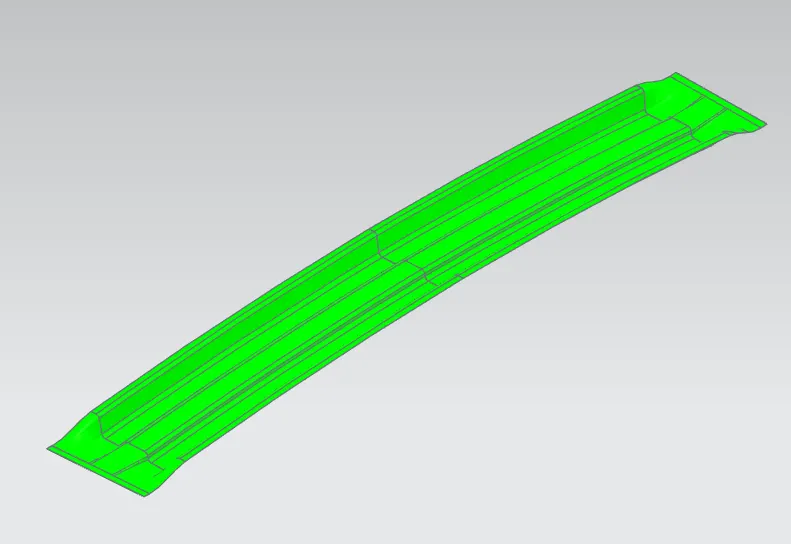
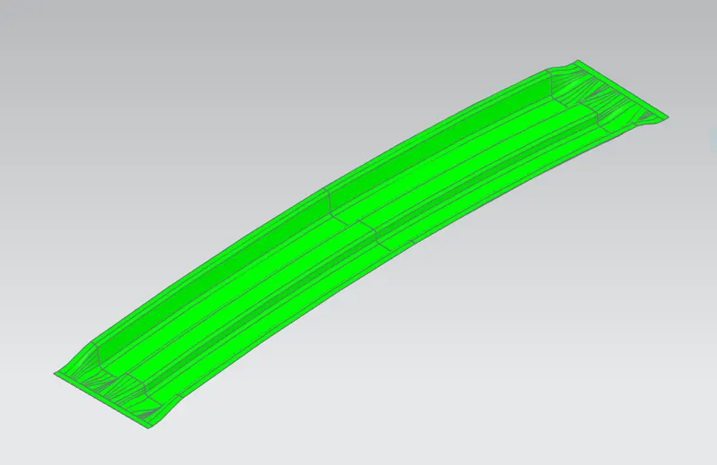
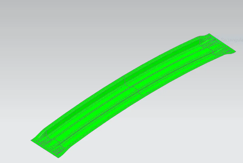
BOW ROOF 1:
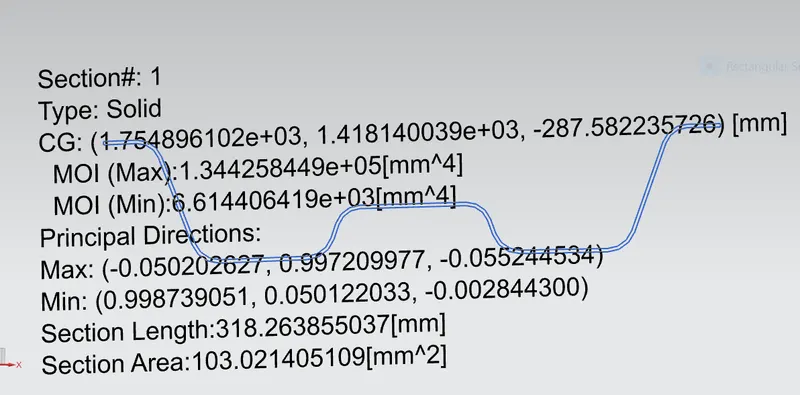
Moment of inertia maximum,( MAX) I max =1.34426 × 10^5 ( mm4)
Moment of inertia maximum ,( MIN) I min =6.6144 x 10^3 ( mm4)
SECTION MODULUS
S= moment of inertia /distance from the neutral axis to any given fibre
S = I / y
Y = 34.95 mm
FOR MINIMUM MOI :
S= 6.6144 x 10^3 ( mm4)/ 34.95 mm
S min = 189.2532 mm3
BOW ROOF 2:
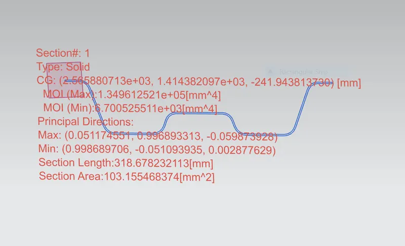
Moment of inertia maximum,( MAX) I max =1.344961 × 10^5 ( mm4)
Moment of inertia maximum ,( MIN) I min =6.70052 x 10^3 ( mm4)
SECTION MODULUS
S= moment of inertia /distance from the neutral axis to any given fibre
S = I / y
Y = 34.95 mm
FOR MINIMUM MOI :
S= 6.70052 x 10^3 ( mm4)/ 34.95 mm
S min = 191.2872 mm3
CENTRAL ROOF RAIL :
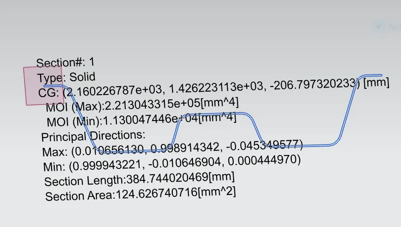
Moment of inertia maximum,( MAX) I max =2.21304 × 10^5 ( mm4)
Moment of inertia maximum ,( MIN) I min =1.13004x 10^3 ( mm4)
SECTION MODULUS
S= moment of inertia /distance from the neutral axis to any given fibre
S = I / y
Y = 59.96 mm
FOR MINIMUM MOI :
S= 1.13004 x 10^3 ( mm4)/ 59.96 mm
S min = 188.466 mm3
CONCLUSION :
Hence the roof , front roof rail, bow roof rails , central roof rail and the rear roof rail is designed by following the master sections and the moment of inertia , section modulus and draft analysis are carried out to check feasibility manufacturing.