Roof challenge
Objective:
- Design of automobile roof with proper Bow roofs and reinforcements for the given Class-A surface.
- Perform Heat distortion & Snow load calculations.
- Finally, Draft analysis on all Sheet metal components.
Description:
Car roof is a component which protects the passengers & driver from the Dust, Wind and is top portion of the car. The design of roof varies from company to company and model to model like some models have sunroof, some have entire roof made using the fibre and there are some cars with no roofs but, the car with roof (made of Steel, Aluminium is safer than other). The roof designed should be strong enough such that it should prevent injuries on passengers & driver in accident (mostly in rollover accident).
Materials like Aluminium, Steel & Fibre glass are used for roof.
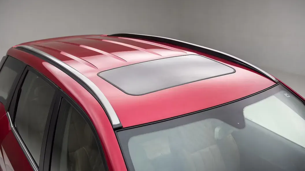 |
| Roof of SUV |
There different types of roofs for car, which are as follow
- Convertible roofs.
- Hardtops.
- Sunroofs.
- T-tops.
- Targa tops.
- Vinyl roofs.
Roof Crush test:
Roof structure with poor strength may cause more injuries or sometimes even death of passengers and driver. Previously the fatality rate due to the car rollover accident was high, as the roof structure was not so good and severe head injuries could have been seen.
To reduce the fatality rate due to rollover accident “THE HIGHWAY SAFETY ADMINISTRATION” of different countries set some standards and regulations according to their road conditions.
Roof crush test performed by U.S.A is discussed.
FMVSS 216 (Federal Motor Vehicle Safety Standard 216), Roof Crush Resistance, establishes strength requirements for the passenger compartment roof of passenger cars, multipurpose passenger vehicles, trucks and buses with a GVWR of 2722 kilograms or less. The purpose of the standard is to reduce deaths and injuries due to the crushing of the roof into the passenger compartment in rollover accidents.
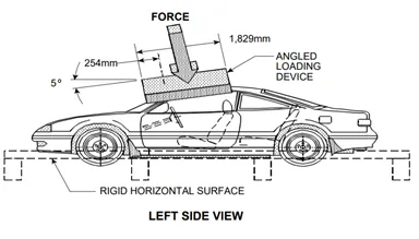
The prescribed static loading device is a rigid unyielding rectangular block 762 millimetres by 1,829 millimetres. It shall not move more than 127 millimetres to achieve the specified resistive load when applied to the forward edge of a vehicle’s roof. The passenger car's sills shall be placed on a rigid horizontal surface and fixed rigidly in position. The vehicle's windows shall be closed and the doors shall be locked. Any convertible top or removable roof structure shall be secured in place over the occupant compartment. Remove roof racks or other non-structural components.
The force shall be applied in a downward direction perpendicular to the lower surface of the static loading device at a rate of not more than 13 millimetres per second until reaching the compliant resistive load. The test shall be completed within 120 seconds. The static loading device shall be guided throughout the test so that it moves, without rotation, in a straight line with its lower surface oriented as follows and as shown in Figures below.
- Its longitudinal axis is at a forward angle (side view) of 5º below the horizontal, and is parallel to the vertical plane through the vehicle's longitudinal centreline.
- Its lateral axis is at a lateral outboard angle, in the front view projection, 25º below the horizontal.
- Its lower surface is tangent to the surface of the vehicle.
- The initial contact point, or centre of the initial contact area, is on the longitudinal centreline of the lower surface of the static loading device and 254 millimetres from the forward most point of the centreline.
- If the vehicle being tested is a multipurpose passenger vehicle, truck, or bus that has a raised roof or altered roof, and the initial contact point of the static loading device is on the raised roof or altered roof to the rear of the roof over the front seat area, the plate is positioned so that the midpoint of the rearward edge of the lower surface of the static loading device is within 10 mm of the transverse vertical plane located at the rear of the roof over the front seat area.
 |
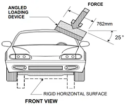 |
| Roof crush test according to FMVSS 216. | |
Design methodology:
1 Extract the required surface from the given input surface/ Class A surface.
2 Design Front, rear & bow roof rails.
3 Perform the Heat distortion & Snow load criteria calculations.
4 Perform Draft analysis on each component.
Inputs:
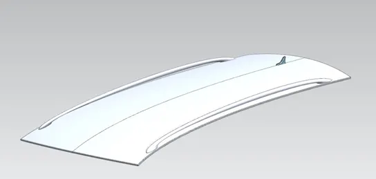
The styling team provides us a Class A surface for which we need to provide roof rails and perform draft analysis and make sure the components are manufacturable, if not send a report to the styling team mentioning the changes that to be done to meet the manufacturability.
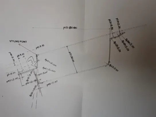
The class A surface of the roof, and master section of the front roof rail are given as input.
 |
 |
| Master section for front roof rail. | Class-A surface. |
Roof top:
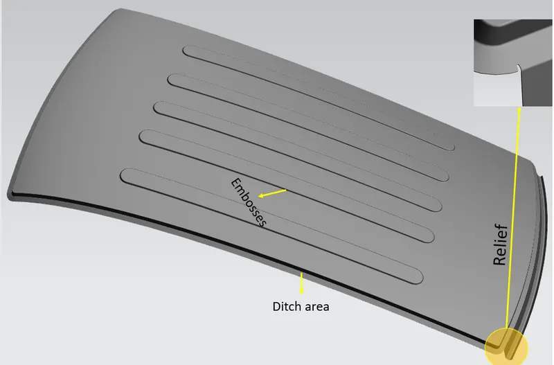
From the given styling surface the roof top with ditch area is created and thickness of 0.75 is maintained. At the rear end reliefs are provided and sharp corners are made smooth using bridge curve to prevent stress concentration.
Finally, embosses are provided to the roof top for better strength.
 |
| Roof top |
Roof Rails:
Roof rails provide strength (the front and rear help in placing the wind shields) to the roof of the automobile, number of roof rails depends on the design and length of the roof. Some have sunroof where the number of roof rails used will be less and in small cars (like Sedan, Hatchback, etc..). If the entire roof is having glass then the design changes, in these cases the reinforcements are added at the sides of BIW.
1. Front roof rail:
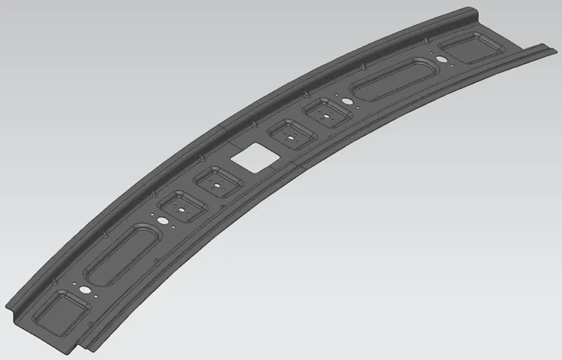
Front roof rail is designed according to the given master section. Further darts and embosses are furnished on some portion of the front roof rail to increase the strength of the front rail. A gap of 5mm is provide between the roof surface and the rail roof side flange. Thickness of 0.75mm maintained.
 |
| Front roof rail |
2. Rear roof rail
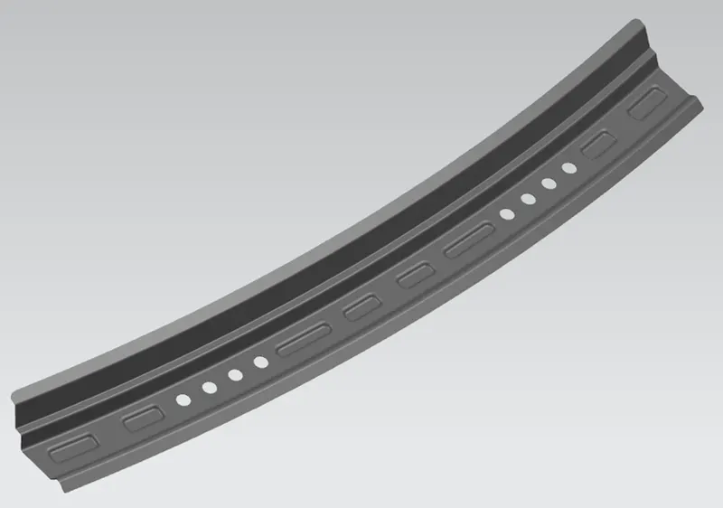
It provides the strength to the rear part of the roof so that the back door can be mounted. Bead and embossing are done on the surface to provide the local strength to the rear rail. Thickness of 0.75mm maintained.
 |
| Rear roof rail |
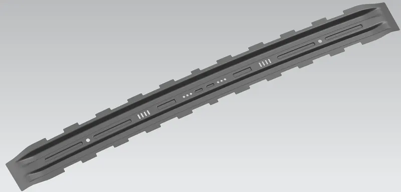
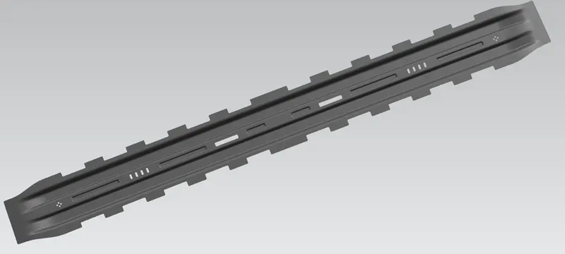
3 Bow roof-1 & Bow roof-2
Bow roofs provide strength to the roof for load carrying. The cross-section of the bow roof is ‘W’ so as to provider more strength to the roof. Embossing is done on the surface to provide the local strength to the bow roofs. The rear side of the rail is spot welded with the ditch area of the roof and the other side is attached using mastic sealant.
Thickness of 0.75mm is given for both bow roofs.
 |
| Bow roof-1 |
 |
| Bow roof-2 |
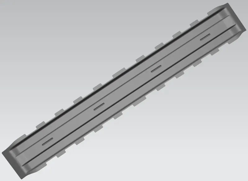
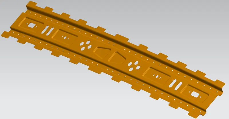
4 Centre roof rail & reinforcement:
The centre roof rail needs to be stronger as compared to other rails for which we can use a reinforcement for the centre roof rail. Embossing is done to provide local strength and finally, the centre roof rail and reinforcement are spot welded and then it is attached to the roof using mastic sealant. Thickness of 0.75mm maintained.
 |
| Centre roof rail. |
 |
| Centre roof reinforcement. |
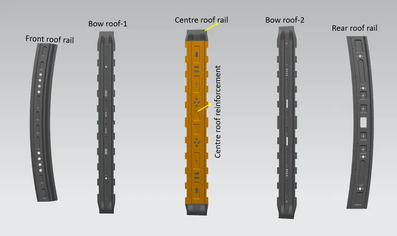 |
| Roof rail positions. |
Curvature study:
In this study we perform two types of calculations
- Heat distortion
- Snow load criteria.
The curvature study for the roof is done only after the design of the roof is frozen. This not followed i every OEM's it is just a self correction for the roof design developed, actual analysis is done by analysis team.
a. Heat distortion calculation:
This calculation is done to understand the better position for placing the bow roofs. The strength of the roof gets weakened when it is exposed to higher temperature due to which the sagging of the roof occurs and sometimes it may enter the plastic state.
By performing this calculation, we can determine whether the position of the bow roofs is acceptable or not. This is performed before sending the component to the analysis team by we will be bit sure about the placement of the bow roofs. Formula for Heat distortion,
W = [1.73*10^(-3)*L] + [1.85*10^(-8)*(R^2)/t] + [ 1.10*10^(-3)*l] - 2.68 .......... (1)
Judgement Condition: OK< 2.7> 3.1
Where,
L = Roof Length in X-Direction[mm] (Roof dimension in 0-Y)
R = Roof curvature
R = 2(Rx*Ry)/(Rx+Ry)
Rx = X curvature
Ry = Y curvature
t = Roof plate thickness [mm]
l = Bow Roof Span [mm]
Procedure to measure Rx & Ry:
1. Consider a plane above the roof (at some distance) & enter the sketch workbench.
2. Draw a line at -3Y (i.e., at -300mm from O-Y axis) and offset it to 100mm on both side of -3Y line.
Draw vertical lines between every two adjacent roof rails. Make these line as reference line.
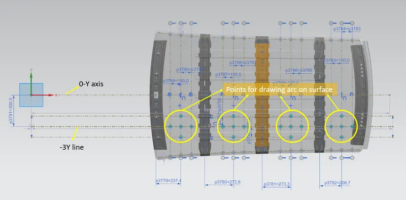 |
| Points creation for drawing arc. |
3. Create points at the intersection of the lines as shown. Then project these points on the roof surface (Styling surface) and using ‘Arc’ option (3-point) draw the arc and measure the radius.
Now, we have Rx& Ry.
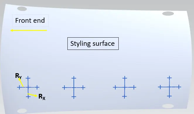 |
| Arcs on styling surface. |
Finally, collecting all the required data (by measuring) substitute equation (1), if W<2.7 then we can go ahead with the positions of bow roof rails.
Tabular column:
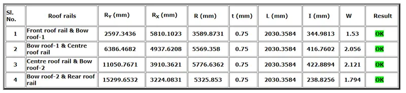
After substituting the values, it can be observed that W is less than 2.7 i.e., the position of the bow roof is good to go.
b. Snow load calculation:
This calculation for automobiles is done in most of the European countries where snow fall is common. After snow fall the snow gets deposited on the roof of the car and the load of the snow deposited tends to bend the roof to some extent, a good roof design must regain its original shape after removal of the snow. If the result of this calculation satisfies the condition, then the roof is good enough to sustain the load. Formula for Snow load calculation,
Qr = [Iy*t2] / [ *s*[(Rx + Ry)/2] ^2*10-8] ........ (2)
Where,
= My*L2x*10-12 ................ (3)
My = Y(Ly-Y) ................ (4)
Judgement condition = Qr ≥ 3.1
t = Roof plate thickness [mm]
Ly = Distance between the front and rear roof Rails on the Vehicle along with 0Y[mm].
Length of Roof panel with the centre point between Roof rail Front /Rear as the reference point of the front and the rear.
Lx = Distance between the Left and Right end of the roof on the Roof BOW [mm]
Width of the roof panel exposed on the surface.
Y = Distance front Roof Rail to Roof BOW [mm]
s = Distance for which Roof BOW bears divided load [mm]
s = L1/2 + L2/2
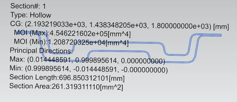
Iy = Geometrical moment of inertia of Roof BOW (Y cross-section) [mm4]
Rx = Lateral direction curvature radius of roof panel Y cross-section on Roof BOW [mm]
Roof panel curvature Radius of the Length Lx in Front view
Ry = Longitudinal Direction curvature radius of the Roof panel X cross-section on Roof BOW [mm]
Procedure to measure Rx & Ry:
1. Consider a plane above the roof (at some distance) & enter the sketch workbench.
2. Draw a line at 0Y and offset it to 100mm on both side of 0-Y line.
Draw vertical lines between every two adjacent roof rails. Make these line as reference line.
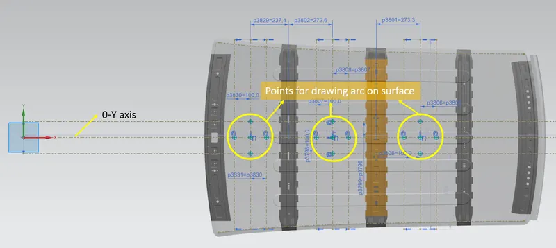 |
| Points creation for drawing arc. |
Here, we can’t’ have L2 in fourth case (Rear roof rail and Bow roof-2) so we consider only first three cases.
3. Create points at the intersection of the lines as shown. Then project these points on the roof surface (Styling surface) and using ‘Arc’ option (3-point) draw the arc and measure the radius.
Now, we have Rx& Ry.
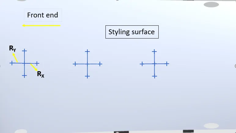 |
| Arcs on styling surface. |
Moment of inertia of:
a. Bow roof-1
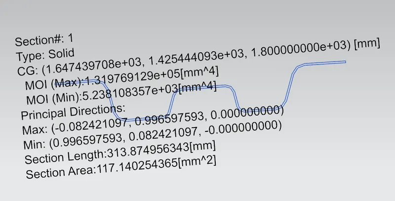 |
| Section inertia analysis of Bow roof-1. |
b. Centre roof rail and reinforcement
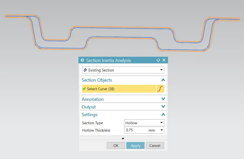 |
 |
|
Section inertia analysis of Centre roof rail and reinforcement. |
|
c. Bow roof-2
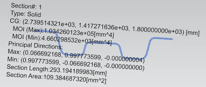 |
| Section inertia analysis of Bow roof-2. |
Collect the required data from the roof design and substitute in the snow load formula, if Qr is less than 3.1 than it fails.
Tabular Column:
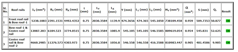
As we can see from the above tabular column that Qr>3.1, So the results are satisfied which means the roof won't enter the plastic state.
Draft analysis:
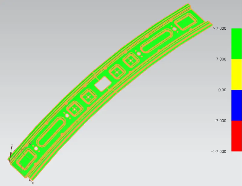
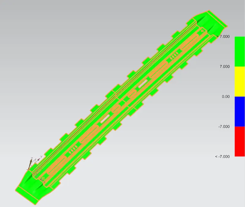
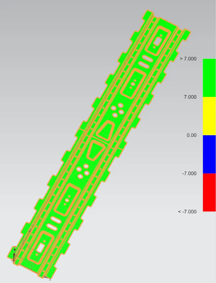
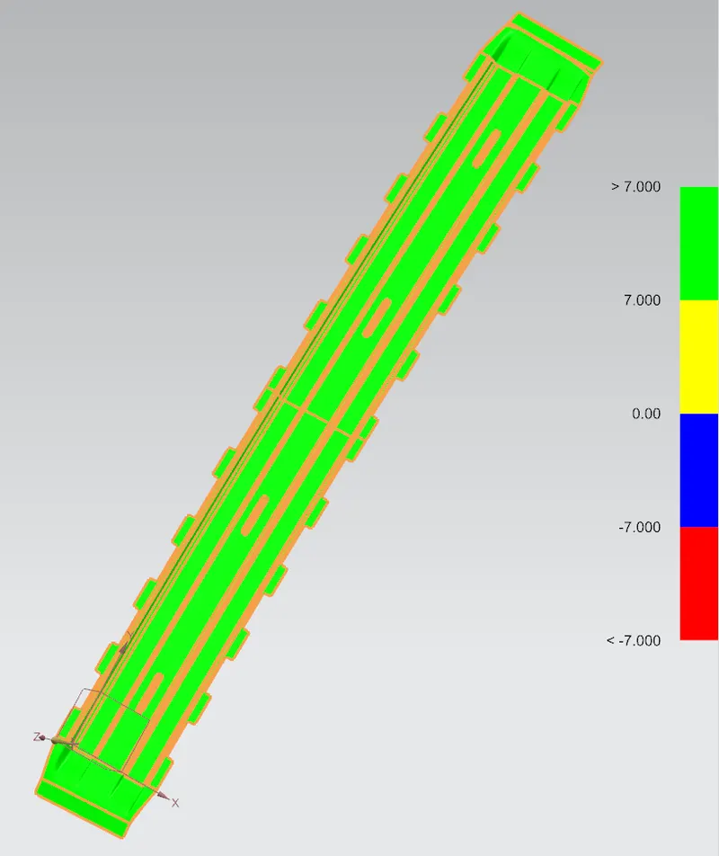
No component can be ejected at 90degree angle there should be some drat given for easy removal after performing the respective operation to form a Sheetmetal component. The minimum draft angle of 7degrees should be provided for the Sheetmetal components so that there shall be no deformation in the component after it is removed from the punching or any other operation.
Draft analysis is performed on each and every Sheetmetal component (with minimum 7degrees draft angle) and the results are satisfied.
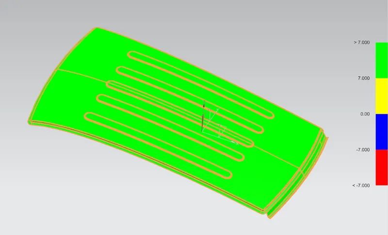 |
| Draft analysis of Roof top. |
 |
| Draft analysis of Front roof rail. |
 |
| Draft analysis of Bow roof-1 |
 |
| Draft analysis of Centre roof rail Reinforcement |
 |
| Draft analysis of Centre roof rail. |
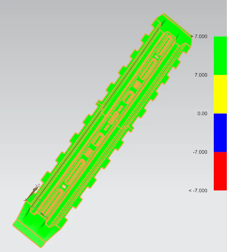 |
| Draft analysis of Bow roof-2. |
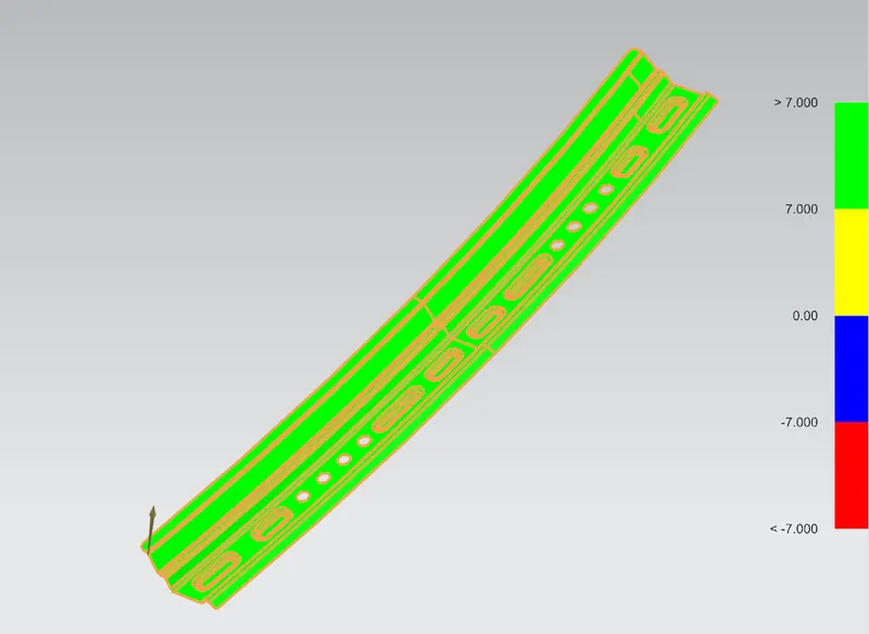 |
| Draft analysis of Rear roof rail. |
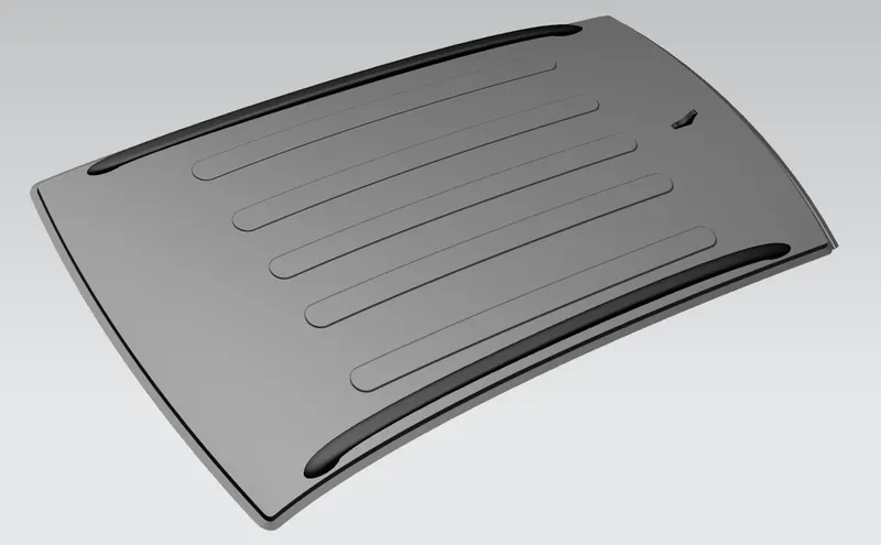
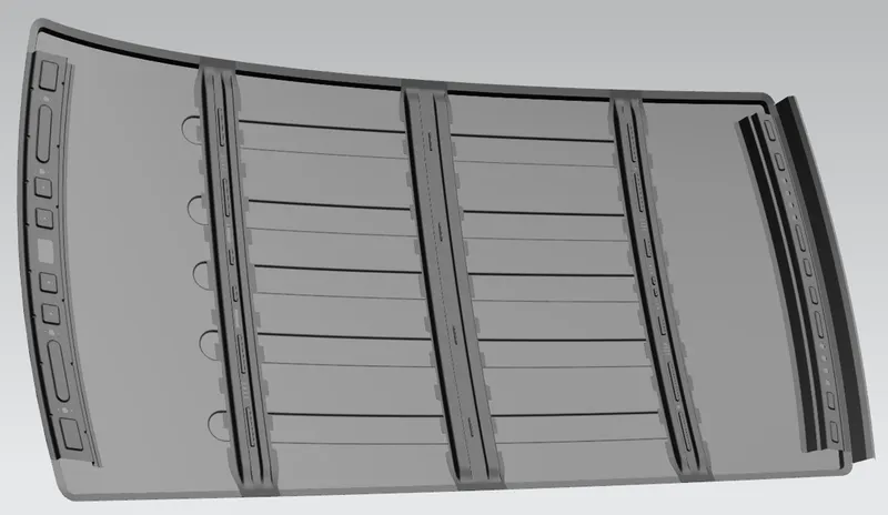
Final rendered snap of Car Roof with roof rails.
 |
 |
Conclusion:
- Roof and roof rails are designed using the styling surface.
- Results of Heat distortion & Snow load calculations are satisfied.
- Draft analysis of each component is carried out and all components satisfy the draft condition (7degrees).