Roof challenge
Design of Roof
Objective
The main objective of this project is to learn the basic tools, commands, and 3D modeling of the Roof Design using Siemens NX CAD. The objectives of this project are as follows:
- To understand and learn the basic Graphical User Interface (GUI) of Siemens NX CAD
- To understand and develop the reinforcements and essential flanges for the given dumb solid body of the roof.
- To design the essential flanges and reinforcements for the Ditch Area, Front Roof Rail, Bow Roofs, Centre Roof Rails, Rear Roof Rails.
- To provide appropriate dimensioning to the roof solid body and calculate the roof design's draft analysis and section modulus.
- To determine and justify the position of the Bow Roofs and have to calculate the Heat Distortion and Snow Load criterion for the roof designs.
Introduction
An automobile roof is the piece of an automobile that sits over the voyager compartment, protecting the vehicle inhabitants from sun, wind, rain, and other external segments. Under the styling surface seen from an outside point of view, various designs under the roof add to its fortitude and strength. The number of such reinforcement structures/maintains contrast concerning the size of the vehicle. They are basically presented on praise areas of the roof to improve strength.
These are the Front Roof Rail, Rear Roof Rail, Center Roof Rail, and Bow Roof Design which are spot-welded to roof flanges and ditch areas and improve NVH regard by growing the strength of the roof using mastic sealants.
Crush Test for Roof:
Security point of view vehicle roof expects an incredibly indispensable part especially rollover kind of accidents, in which vehicle tips over onto its side of the roof. Likewise, vehicle rollover crashes are just a few fatalities and a couple of head, neck, and spine trauma all through the planet. Hence, voyager prosperity is also a crucial limit in front of OEMs. It isn't only an exhibiting system yet moreover a responsibility determined by overall standards that are as of now situated in a couple of countries and a regulatory need. Along these lines, strength is an imperative reason for designing a vehicle roof. The strength of the roof design to inhabitant protection in certifiable rollover crashes, requiring the maximum moving distance of the roof development should be under 127 mm (5 in.) when the started load is 1.5 events the vehicle weight.
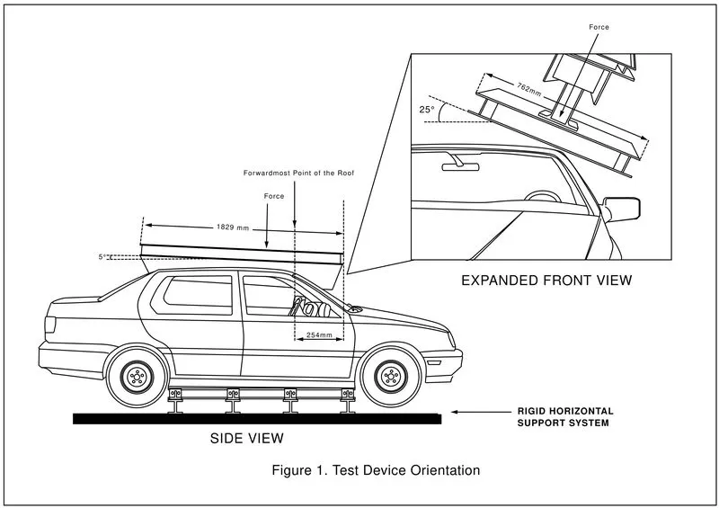
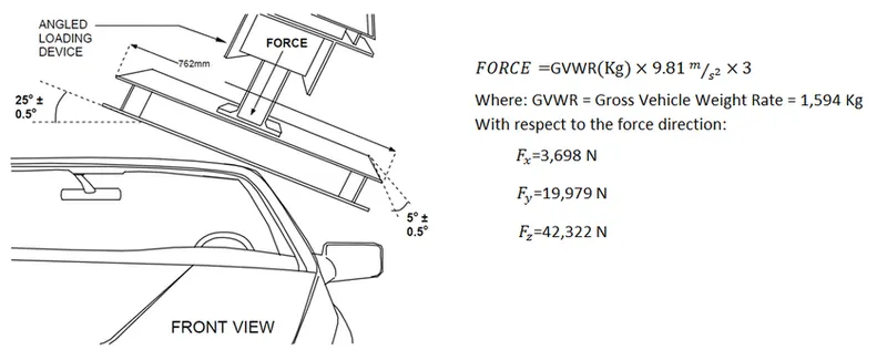
The voyager vehicle will be firmly situated or arranged on an even surface with the doorways secured and the window for the test. Additionally, a level, unyielding square with a lower surface a square shape assessing 30 inches wide by 72 crawls long (762mm X 1829mm) won't move more than 5 inches(127mm), assessed as the distance between the primary space of the lower surface of the test device and its territory as the predefined power level is reached, when it is used to apply the force of 1.5 events the unloaded vehicle weight (UVW) or 5000 lbs(22224N), whichever is less, to either side or forward edge of the vehicle. This test can be driven on either side of the roof structure, the front left or the front right side anyway not on the different sides in a solitary test, and still meets the necessities of the test. The unyielding plate won't move speedier than 0.5 inches/second and the force applied on the plate won't outperform the lesser of 1.5 events the unloaded vehicle weight (UVW) imparted in kilograms expanded by 9.8 or 5000lbs (22240N). Also, the orientation of the force will be sliding and perpendicular to the lower surface of the unbendable plate and so much that it moves in a precise design without turn. The length of the test won't outperform 120 seconds. The longitudinal rotation of the plate is pitched forward at a 5 º point as seen from the side of the explorer vehicle.
The lateral axis or the move of the plate is so much that it shapes a 25 º separable point with a level surface as seen from the front of the voyager vehicle. The lower surface of the plate will reliably stay in contact with the outside of the roof. The fundamental point contact is 10 inches (254 mm) from the principle edge of the plate and as per the longitudinal axis on the lower side of the plate. Designed Roof. Following these design considerations and consequently creating the parts helps the vehicle with performing better, in reality, condition adhering to the testing limit which assurances to avoid or minimize the earnestness of injury during the episodes of the vehicle during lethal accidents.
Design Consideration of Roof:
- Visibility Criteria
- Curvature Study
- Draft Analysis
- Heat distortion and Snow load criteria
- Safety Parameters
- Head Clearance
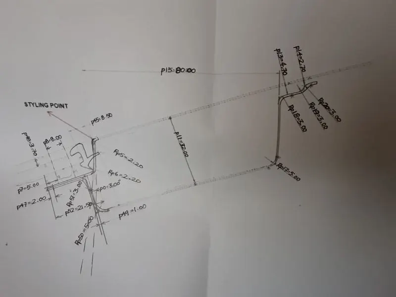
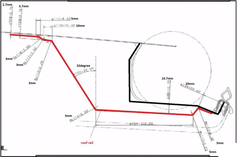
Master Sketch:
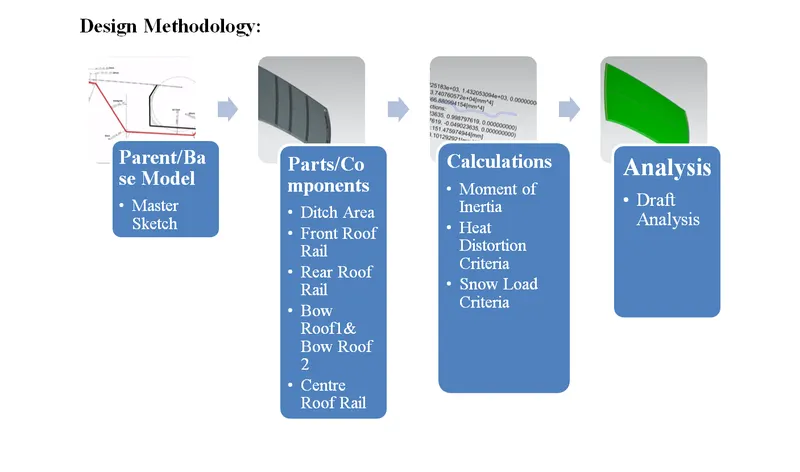
Design Methodology:
Designing several areas for an outer panel of the Roof:
- Ditch Area:
- Front Ditch Area: From dump solid part class A surface is removed and ditch areas are made considering the limit decided in the going with master section. The flange of around 15mm was made with the law development request, corner help at rear flanges, and a positive draft of various degrees considering for the drawing action measure. The overall thickness of sheet metal considers 0.75mm all through.
- Rear Ditch Area: The surface is adjusted from the outside board to shape the ditch locale and with the law development request, corner lightening at rear flanges, and positive draft in required degree considering for the drawing movement measure. The overall thickness of sheet metal for the outer board consider 0.75mm all through.
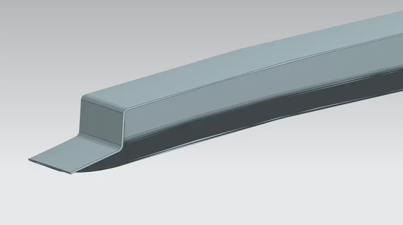
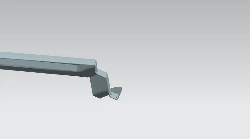
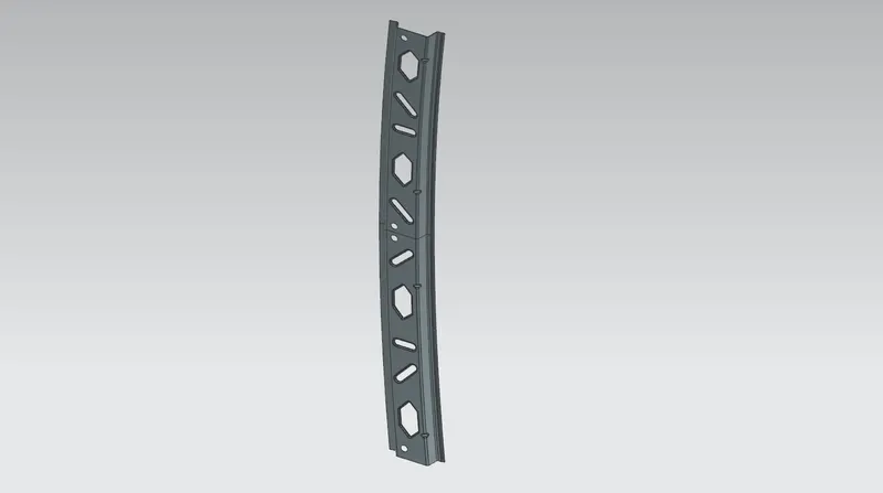
- Front Roof Rail:
The front rail upholds the rooftop outside shell at the front end. It is mounted with assistance rooftop rail fortress on the two terminations. The rails are equipped with embosses to improve the strength over the length and the rail is connected with the external board utilizing mastic sealants on one side and the other joinery is spot welded.
The going with centers are considered:
Headroom clearance: 80 mm least
Front visibility rules: 21.50mm projection for 15° vertical overview point as indicated by the master section.
Sheet metal thickness: T= 0.75mm
Emboss height: 2 < 3T
Flange length: 13.2 > 3T+R
Radius: (R=3mm and 5mmm )> T
- Rear Roof Rail:
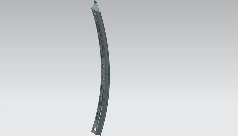
The assistance is joined to the Back Door and the Body Side Outer and the inner panels. Moreover, it is regularly created utilizing Body Side Outer piece and thus the thickness of the rail is 0.65 mm. Like the Front Roof Rail design, we need to examine the rear Headroom Clearance and the rear visibility principles while designing the Rear Roof Rail. Wellsprings of data are taken from the rear master section that showed up in fig.
The going with centers are considered:
Headroom clearance: 120mm least
Sheet metal thickness: T= 0.75mm
Emboss height: 2 < 3T
Radius: (R=3mm and 5mmm )> T
- Bow Roof 1 & Bow Roof 2:
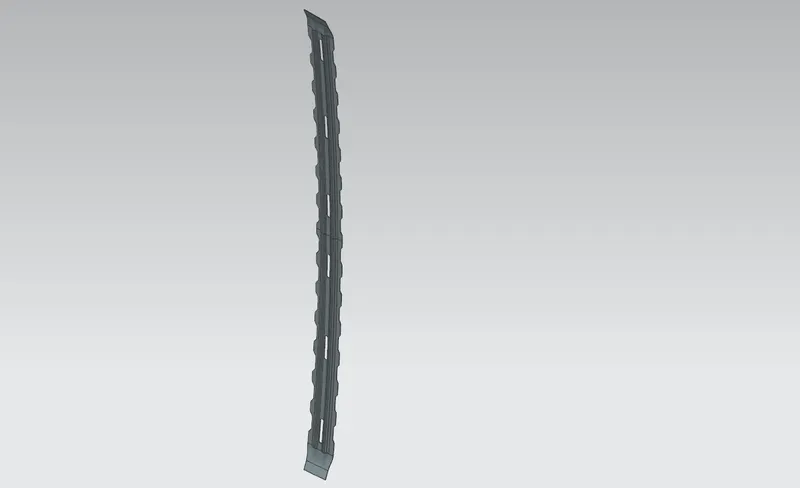
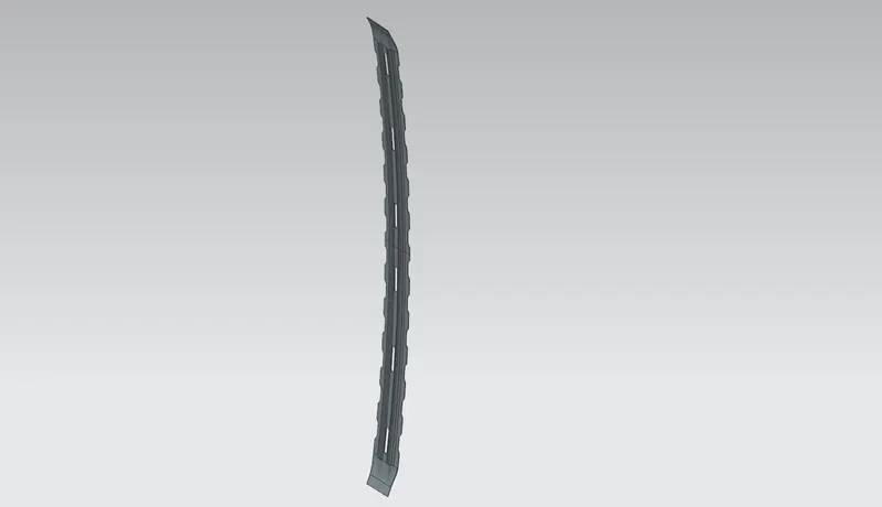
The Bow roofs are given to improve the torsional stiffness and load-bearing capacity of the roof structure. The number of bow roofs gave will depend on the overall segments of the roof. The more expanded the roof more the bow roofs are fused into the BIW layout They are associated with the outer board using mastic sealants. Each mastic point will have up to 80 mm indirect powerful area. The arranging of bow roofs is done ward on curve assessment. The heat distortion criteria and snow load criteria are checked to examine the circumstance of the bows in various conditions.
Sheet metal thickness of 1.25mm used with W cross-section pattern. Dart patterns are used to grow the stiffness and strength in the structure over the length across the roof. Remarkable indents on the flanges have obliged the utilization of mastic sealant. Either end flanges of the bow roof are levelly offset the roof flanges to join by spot welding. Both bow roof 1 and bow roof 2 are near in estimation and pattern simply the curve profile is particular at isolated positions.
- Centre Roof Rail:
Focus roof rail is given to reasonably maintain the level space of the roof as it is more exposed to disappointment under the movement of the load. For the most part, the center reinforcement roof rail will be put at the point of convergence of the roof interfacing the B segment support structure which achieves added support in the turnover of the test. The thickness of the center bow roof is 1.5mm thickness. Central rib type design is embraced here to take a maximum load of roof upheld with darts and angled shape at flange end are considered to grow the surface district and load distribution to basic BIW layout body during ideal and impact condition. This is design diverges from the certifiable BIW diagram.
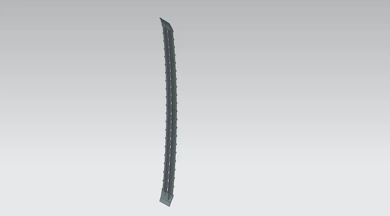
Bow Roof Rail Calculations:
- Heat Distortion Criteria:
Calculation of Heat Distortion for Roof:
W = [1.73 x 10^(-3) x L] + [1.85 x 10^(-8) x (R^2)/t] + [ 1.10x10^(-3) x l] - 2.68
Judgement Condition : OK< 2.7> 3.1
Where,
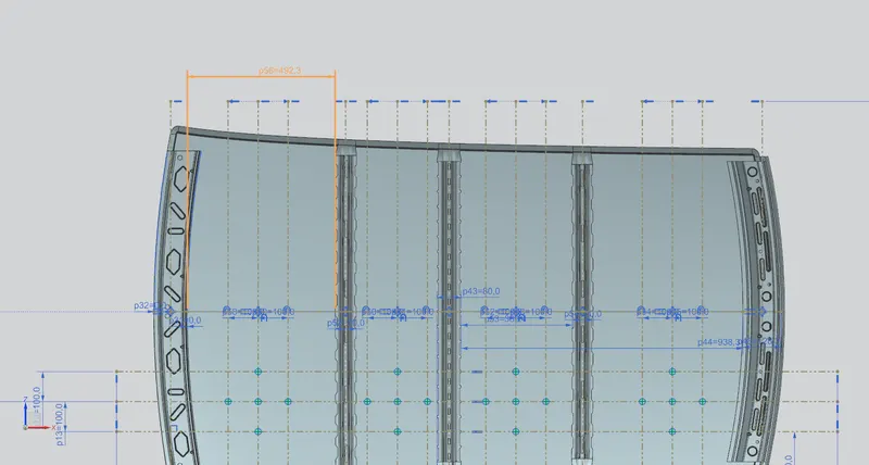
L = Roof Length in X-Direction[mm](Roof dimension in 0-Y)
R = Roof curvature
R = 2(Rx*Ry)/(Rx+Ry)
Rx = X curvature
Ry = Y curvature
t = Roof plate thickness [mm]
l = Bow Roof Span [mm]
- Vishal_Heat_Distortion_L
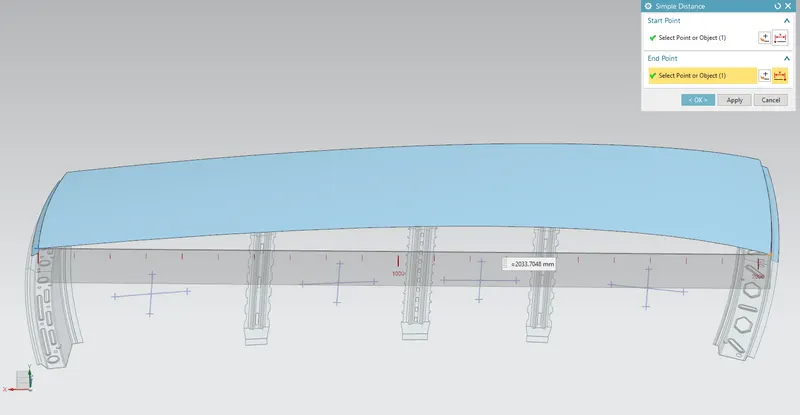
- Vishal_Heat_Distortion_Rx
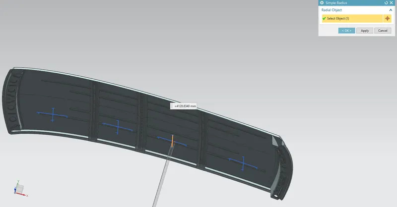
- Vishal_Heat_Distortion_Ry
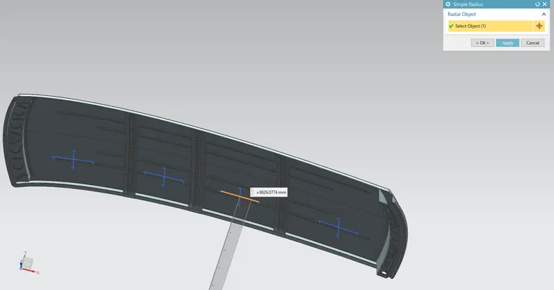
- Vishal_Heat_Distortion__l
Thickness for the Roof:
Roof Outer Panel, t = 0.75 mm
Front Roof Rail, t = 1.25 mm
Bow Roof Rail, t = 1.25 mm
Centre Roof Rail, t = 1.25 mm
Bow Roof Rail 2, t = 1.25 mm
Rear Roof Rail, t = 1.25 mm

- Snow Load Criteria:
Calculation of Snow Load Criteria for Roof:
Qr = [Iy x t2] / [α x s x [(Rx + Ry)/2]2 x 10-8]
Note: The Qr value given over here is correct. There was a typo error in the formula given in the video.
Where,
α = My x Lx2 x 10-12 , My = Y(Ly-Y)
Judgment condition: Qr ≥ 3.1
250 ≤ s ≤ 380
t = Roof plate thickness [mm]
Ly = Distance between the front and rear roof Rails on the Vehicle along with 0Y[mm]
Length of Roof panel with the center point between Roof rail Front /Rear as the reference point of the front and the rear.
Lx = Distance between the Left and Right end of the roof on the Roof BOW [mm]
Width of the roof panel exposed on the surface.
Y = Distance front Front Roof Rail to Roof BOW[mm]
s = Distance for which Roof BOW bears divided load [mm]
s = L1/2 + L2/2
Iy = Geometrical moment of inertia of Roof BOW (Y cross-section )[mm4]
Rx = Lateral direction curvature radius of roof panel Y cross-section on Roof BOW [mm]
Roof panel curvature Radius of the Length Lx in Front view
Ry = Longitudinal Direction curvature radius of the Roof panel X cross-section on Roof BOW [mm]
Roof panel X curvature radius of length s in Side view
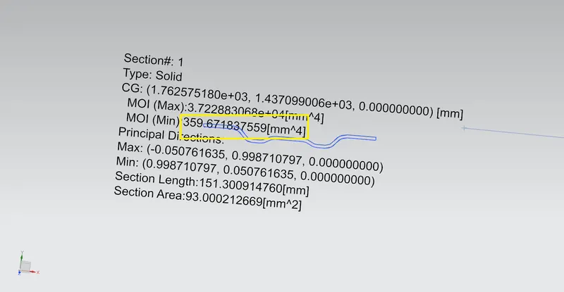
- Vishal_Bow_Roof_Rail_1_Section_Modulus_Snow_Load_Iy
- Vishal_Bow_Roof_Rail_2_Section_Modulus_Snow_Load_Iy
- Vishal_Centre_Roof_Rail_Section_Modulus_Snow_Load_Iy
- Vishal_Snow_Load_Lx
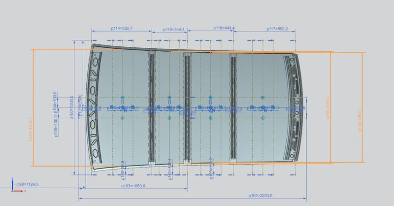
- Vishal_Snow_Load_Ly
- Vishal_Snow_Load_L1_L2_Y
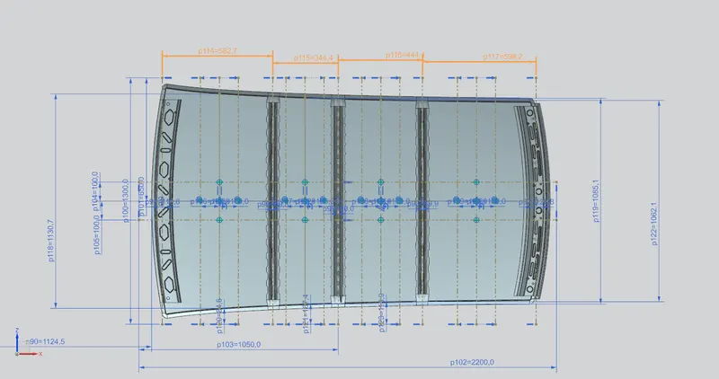
- Vishal_Snow_Load_Rx
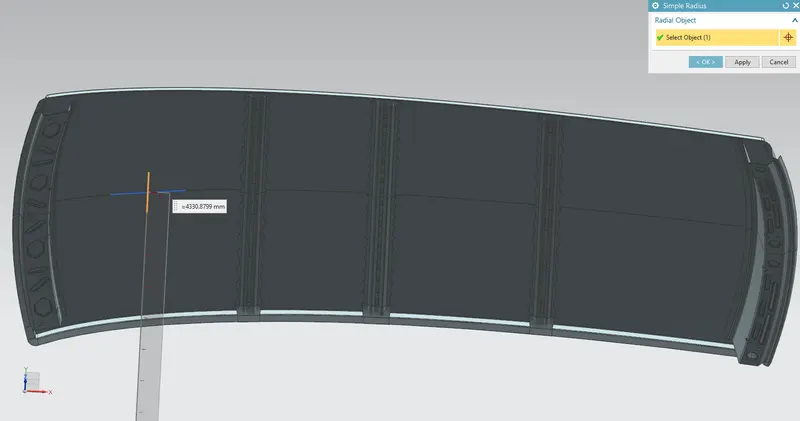
- Vishal_Snow_Load_Ry
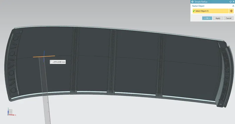
Thickness for the Roof:
Roof Outer Panel, t = 0.75 mm
Front Roof Rail, t = 1.25 mm
Bow Roof Rail, t = 1.25 mm
Centre Roof Rail, t = 1.25 mm
Bow Roof Rail 2, t = 1.25 mm
Rear Roof Rail, t = 1.25 mm

Section Modulus Calculation:
- Calculation of Section Modulus for Front Roof Rail:
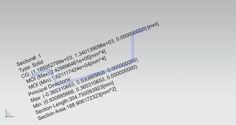
Moment of Inertia (MOI), Imax = 2.429896461 x 10^5 [mm^4]
Moment of Inertia (MOI), Imin = 1.621117424 x 10^4 [mm^4]
Distance between the neutral axis and the extreme end of the object, y = 2033.7048 mm / 2 = 1016.852 mm
Section Modulus, S = Moment of Inertia (MOI), I / Distance between the neutral axis and the extreme end of the object (y)
S = I/y
For Maximum (MOI),
S = (2.429896461 x 10^5 mm^4) / (1016.852 mm)
S= 238.9626476 mm^3
For Minimum (MOI),
S = (1.621117424 x 10^4 mm^4) / (1016.852 mm)
S= 15.94251104 mm3
- Calculation of Section Modulus for Bow Roof Rail 1:
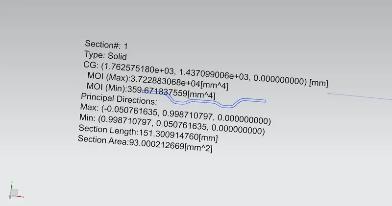
Moment of Inertia (MOI), Imax = 3.722883068 x 10^4 [mm^4]
Moment of Inertia (MOI), Imin = 359.671837559 [mm^4]
Distance between the neutral axis and the extreme end of the object, y = 2033.7048 mm / 2 = 1016.852 mm
Section Modulus, S = Moment of Inertia (MOI), I / Distance between the neutral axis and the extreme end of the object (y)
S = I/y
For Maximum (MOI),
S = (3.722883068 x 10^4 mm^4) / (1016.852 mm)
S= 36.61184782 mm^3
For Minimum (MOI),
S = (359.671837559 mm^4) / (1016.852 mm)
S= 0.3537110981 mm3
- Calculation of Section Modulus for Centre Roof Rail:
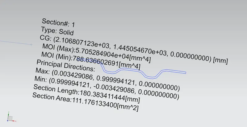
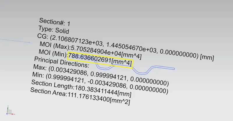
Moment of Inertia (MOI), Imax = 5.705284904 x 10^4 [mm^4]
Moment of Inertia (MOI), Imin = 788.636602691 [mm^4]
Distance between the neutral axis and the extreme end of the object, y = 2033.7048 mm / 2 = 1016.852 mm
Section Modulus, S = Moment of Inertia (MOI), I / Distance between the neutral axis and the extreme end of the object (y)
S = I/y
For Maximum (MOI),
S = (5.705284904 x 10^4 mm^4) / (1016.852 mm)
S= 56.10732834 mm^3
For Minimum (MOI),
S = (788.636602691 mm^4) / (1016.852 mm)
S= 0.7755667518 mm3
- Calculation of Section Modulus for Bow Roof Rail 2:
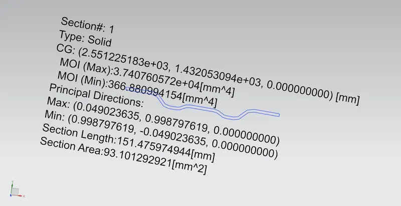
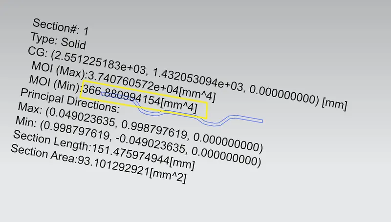
Moment of Inertia (MOI), Imax = 3.70760572 x 10^4 [mm^4]
Moment of Inertia (MOI), Imin = 366.880994154 [mm^4]
Distance between the neutral axis and the extreme end of the object, y = 2033.7048 mm / 2 = 1016.852 mm
Section Modulus, S = Moment of Inertia (MOI), I / Distance between the neutral axis and the extreme end of the object (y)
S = I/y
For Maximum (MOI),
S = (3.70760572 x 10^4 mm^4) / (1016.852 mm)
S= 36.78766007 mm^3
For Minimum (MOI),
S = (366.880994154 mm^4) / (1016.852 mm)
S= 3.608007794 x 103 mm3
- Calculation of Section Modulus for Rear Roof Rail:
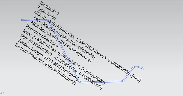
Moment of Inertia (MOI), Imax = 4.262068973 x 10^5 [mm^4]
Moment of Inertia (MOI), Imin = 4.291921741 x 10⁴ [mm^4]
Distance between the neutral axis and the extreme end of the object, y = 2033.7048 mm / 2 = 1016.852 mm
Section Modulus, S = Moment of Inertia (MOI), I / Distance between the neutral axis and the extreme end of the object (y)
S = I/y
For Maximum (MOI),
S = (4.262068973 x 10^5 mm^4) / (1016.852 mm)
S= 0.4191434913 x 103 mm^3
For Minimum (MOI),
S = (4.291921741 x 104 mm^4) / (1016.852 mm)
S= 0.04220792938 x 103 mm3
Draft Analysis:
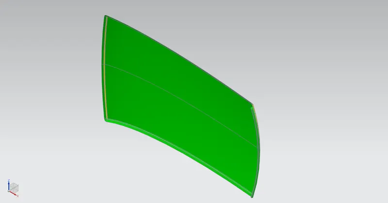
- Isometric View ROP
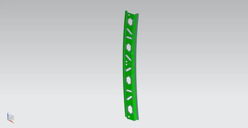
- Isometric View FRR
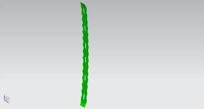
- Isometric View BRR 1
- Isometric View BRR 2
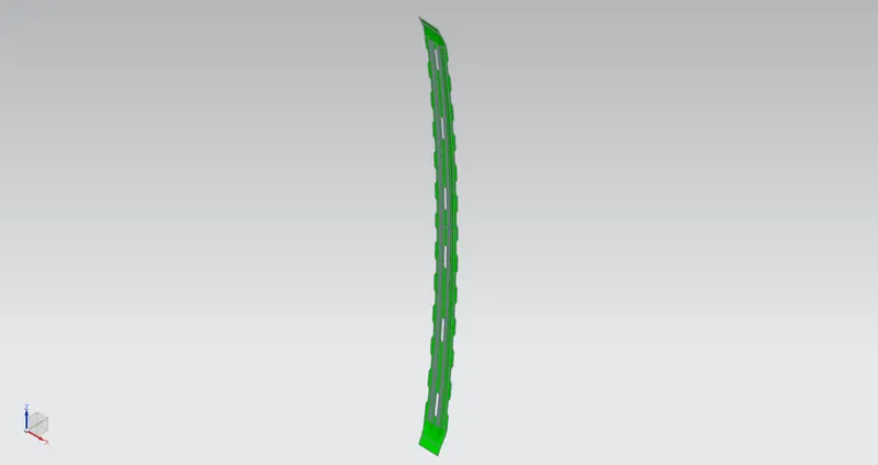
- Isometric View CRR
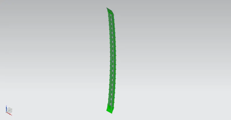
- Isometric View RRR
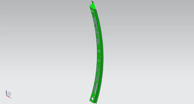
Roof Design Views
- Isometric View
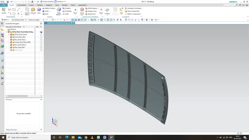
- Front View
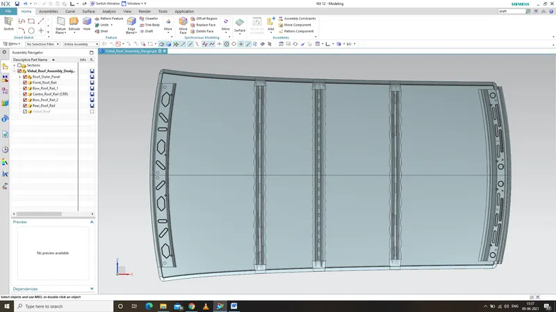
- Top View
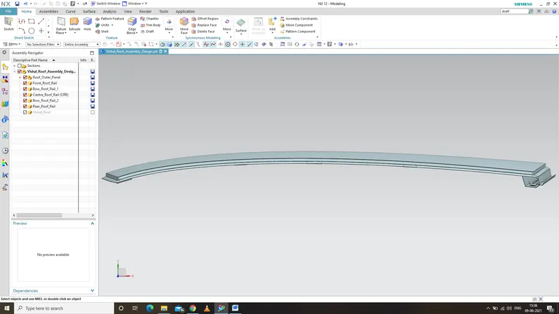
- Side View
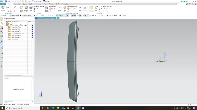
- Assembly Part Navigator 1
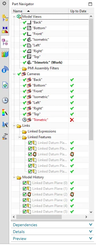
- Assembly Part Navigator 2
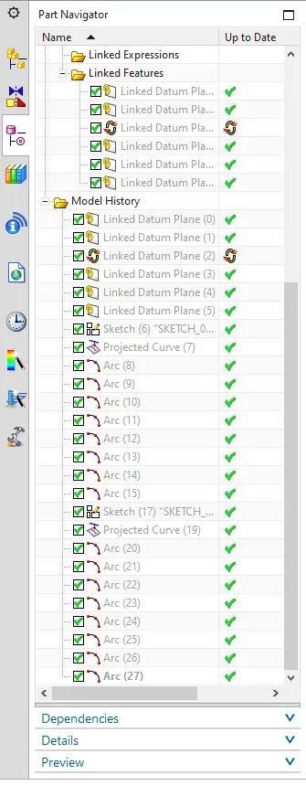
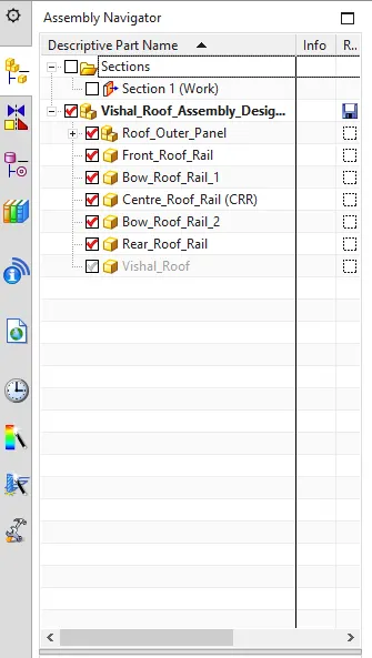
- Assembly Navigator