REVIT_Dynamo Project- 3
1) Using Dynamo create a set of sinusoidal points and create a curve and create a surface out of the curve.
AIM: To create a set of sinusoidal points and to create a curve and surface using dynamo.
TOOLS/COMMANDS USED:
Architectural template
Manage
Dynamo
PROCEDURE:
Step-1: Open a new file in Revit.
Step-2: Open an architectural template.
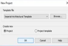
Step-3: Go to manage tab and select dynamo.

Step-4: After selecting manage a new file opens in Revit.
Step-5: Now a new tab of dynamo opens.
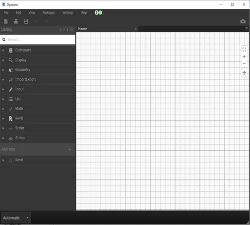
Step-6: Go to the search box in dynamo file and type point by coordinates and range by coordinates.
Step-7: Now type code blocks in the search box and load three code blocks.
Step-8: Rename the code blocks as start, end and type.
Step-9: Give the input values as 10, 200 and 1 to start, end and type respectively.
Step-10: Now join in those 3 code blocks to 3 respective components of range.
Step-11: Now load another code block and prepare 3 components (start, end, type) in it.
Step-12: Now again join those 3 components to the new code block.
Step-13: Now load another code block and rename it as number of values and assign the value as 10.
Step-14: Add a code block and assign 3 components (start, end and number).
Step-15: Now load sine factor and a code block.
Step-16: Rename the code block as amplifier and fix the value of that as 20.
Step-17: Load product factor and assign x, y components to it.
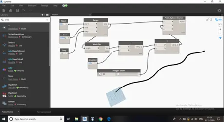
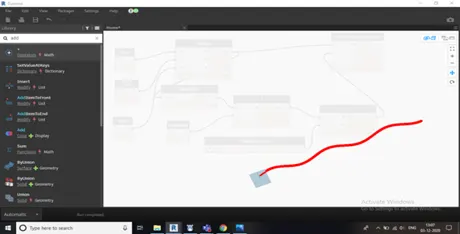
Step-18: Now join sine and amplifier to the product.
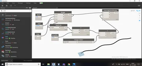
Step-19: Add integer slider and set the minimum, maximum and step value as 20, 50 and 1 respectively.
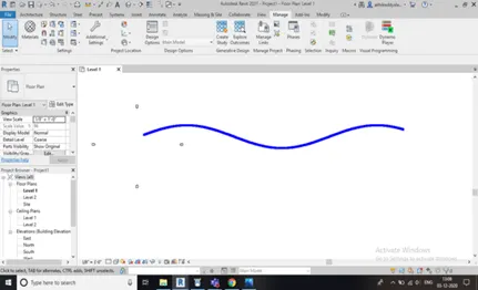
Step-20: Load ass factor and join those values to integer slider.
Step-21: Now add surface to the curve.
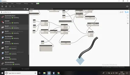
RESULT:
Curve was created successfully by using sinusoidal points and surface was added to it.
2) Create a conceptual layout of floor plan in dynamo. Using the tools available in dynamo link the lines to appropriate model elements in Revit by choosing the wall types and wall parameters. Make use of the sliders to slide through the height of the wall and length of the wall.
AIM: To create a conceptual layout of floor plan in dynamo and to change the dimensions of the model created.
TOOLS/COMMANDS USED:
Architectural template
Manage
Dynamo
PROCEDURE:
Step-1: Open an architectural template.
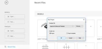
Step-2: Go to manage tab and select dynamo.

Step-3: After selecting manage a new file opens in Revit.
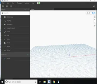
Step-4: Go to search box in dynamo and type point by coordinates for times.
Step-5: Rename the origin, control point 1, control point 2, control point 3.
Step-6: Load a slider box and assign x, y components in it.
Step-7: Connect x from control points 1, 3 to the x in the slider box.
Step-8: Connect y from control points 2, 3 to the y in the slider box.
Step-9: Load line of start, end type for four times.
Step-10: Join origin point to the start point in the line command 1, 2.
Step-11: Join the control point 1 to end point 1, 4.
Step-12: Join the control point 2 to start point 3 and end point 2.
Step-13: Join the control point 3 to start point 4 and end point3.
Step-14: Load wall type by curve and level.
Step-15: Load a slider and rename it as height of the wall.
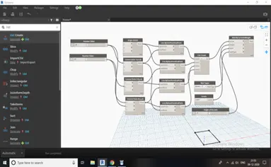
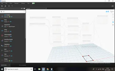
Step-16: Join wall type to wall.
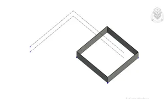
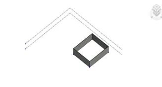
Step-17: Join level to level.
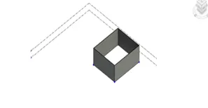
Step-18: Join the slider to height of the wall.
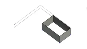
Step-19: By changing the range in slider, the dimensions changes.
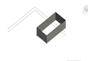
RESULT:
A conceptual layout was successfully created and the dimensions slided in dynamo successfully.
3) Create an array of model elements in Revit. Use dynamo to vary the properties of model elements by using the slider or code block.
AIM: To create an array of model elements in Revit.
TOOLS/
TOOLS/COMMANDS USED:
Family
Mirror
Array
Voids
Dynamo
PROCEDUR:
Step-1: Open a new family.
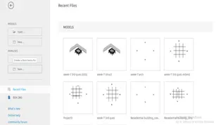
Step-2: A folder appears.
Step-3: Click on English imperial.
Step-4: Select generic model from the available options.
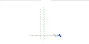
Step-5: Now that generic model appears on your Revit drawing screen.
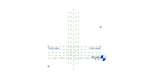
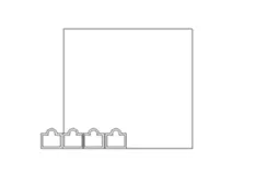
Step-6: Draw few offsets to a vertical member by maintaining a constant offset.
Step-7: Repeat the same thing for horizontal member also.
Step-8: Now set voids forms to all reference planes.
Step-9: Draw a curve by choosing curve option.
Step-10: By selecting line option draw the lines up to the midpoint.
Step-11: Now choose the mirror option and select diagram.
Step-12: Now the diagram will be sticked in the opposite side (left side).
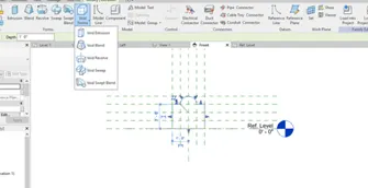
Step-13: Save the model as a new family component.
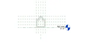
Step-14: Now come back to architectural template and draw a wall.
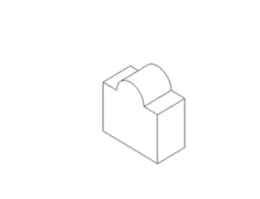
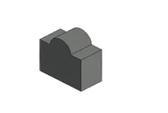
Step-15: Insert that newly created family on to the wall.
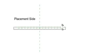
Step-16: Take the screen shots.
RESULT:
An array of model elements was created successfully.
4) Create a conceptual mass in Revit and develop a parametric column by dividing the surfaces and apply the concepts similar to used in parametric walkway modelling. Use triangular bent or square shaped panels to add finish to the parametric column.
AIM: To create a parametric column by using triangular bent.
TOOLS/COMMANDS USED:
Family
Level
Divide surface
Polygon
Tri angle bent
PROCEDURE:
Step-1: Open a new family.
Step-2: A folder appears.
Step-3: Click on English imperial.
Step-4: Select the conceptual mass from the options available.
Step-5: Create another level at a distance of 12’ from the reference.
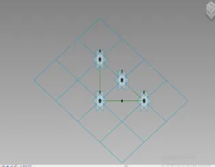
Step-6: Set the work plane by selecting plan view.
Step-7: Set the reference to all control points.
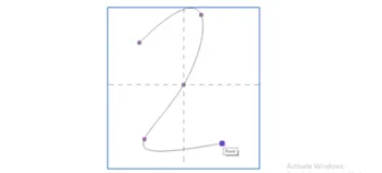
Step-8: Select polygon and set the number of sides as 4.
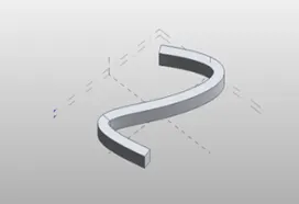
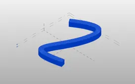
Step-9: Now draw rectangles in all reference planes.
Step-10: Now select all the points and click on filter.
Step-11: Click on foam and choose divide surface.
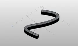
Step-12: Choose the triangle bent pattern.
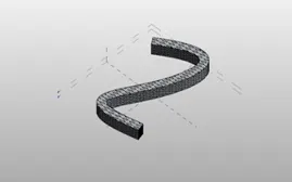
Step-13: Locate a midpoint to that triangle.
Step-14: Now select load into project.
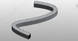
RESULT:
The parametric column was created in a triangle bent option successfully.
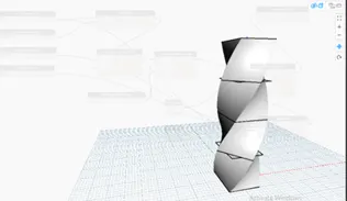
5) Use Dynamo to work on developing a Parametric Stadium. List your parameters and use the visual programming approach to complete the modelling, you can use the concepts discussed in parametric high-rise tower in class for reference.
AIM: To create a parametric stadium using dynamo.
TOOLS/COMMANDS USED:
Architectural
Dynamo
PROCEDURE:
Step-1: Open an architectural template.
Step-2: Go to manage tab and select dynamo.
Step-3: After selecting dynamo a new file opens in Revit.
Step-4: Initially load four integer sliders and rename them.
Step-5: To create a floor, ’points by coordinate’ was added.
Step-6: Add a new code block and assig levels, height of the floor to it.
Step-7: Now load geometry rotate and point origin.
Step-8: Add z-axis.
Step-9: Now connect degrees-geometry point-origin.
Step-10: Add poly surface the option ‘poly surface by loft’.
Step-11: Connect geometry to the cross section.
Step-12: By varying the range in floor rotations, we can observe the change in the model. It will rotate in a circular manner with respect to reference plane.
RESULT:
The parametric stadium in dynamo was successfully created.