REVIT_Dynamo Project- 3
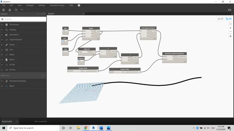
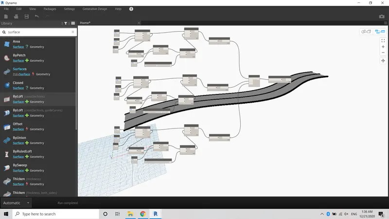
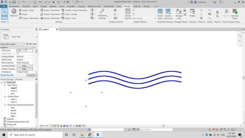
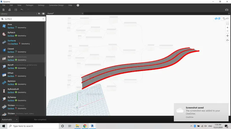
1) Using Dynamo creates a set of sinusoidal points and create a curve and creates a surface out of the curve.
Aim:
To create the set of sinusoidal points, a curve, and a surface out of the curve using dynamo.
Tools used:
* Dynamo
* Points
* Curve
* Loft
Procedure:
Step 1:
1) Open a Dynamo tool by clicking the manage tab in the Revit application
2) Search point and insert into the dynamo screen
3) Rename it as Origin, mid, and endpoint
Step 2:
1) Create a code block and enter the value as a;b;
2) Create an Integer slide and set the minimum and maximum values
3) Connect the integer slide and code block
Step 3:
1) Connect the code block with the points which we created.
2) a to the origin point, b to endpoint x, and formula to midpoint x
Step 4:
1) Switch the screen as 3d preview
2) Now the screen will show the 3 straight points which is the origin, mid, and endpoint
Step 5:
1) create a number slider and connect it with a code block
2) This step makes to create a curve from a sinusoidal point
Step 6:
1) Now the curve has been successfully created from the sinusoidal point
Step 7:
1) Now we need to make the surface of this created curve
2) Create a plan parameter and connect it with a code block
3) Create a List and connect it with a NURBS curve
Result:
Hence the surface of the curve has been created successfully
_______________________________________________________________________________________________________________________________________________________
2) Create a conceptual layout of a floor plan in dynamo. Using the tools available in dynamo link the lines to appropriate model elements in Revit by choosing the wall types and wall parameters. Make use of the sliders to slide through the height of the wall and length of the wall.
Aim:
To create a layout by choosing the wall types and wall parameters using dynamo
Tools used:
* Dynamo
* Wall
* Wall type
Procedure:
Step 1:
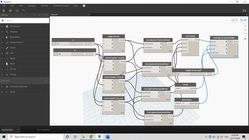
1) Open a Dynamo tool by clicking the manage tab in the Revit application
2) Search point and insert into the dynamo screen
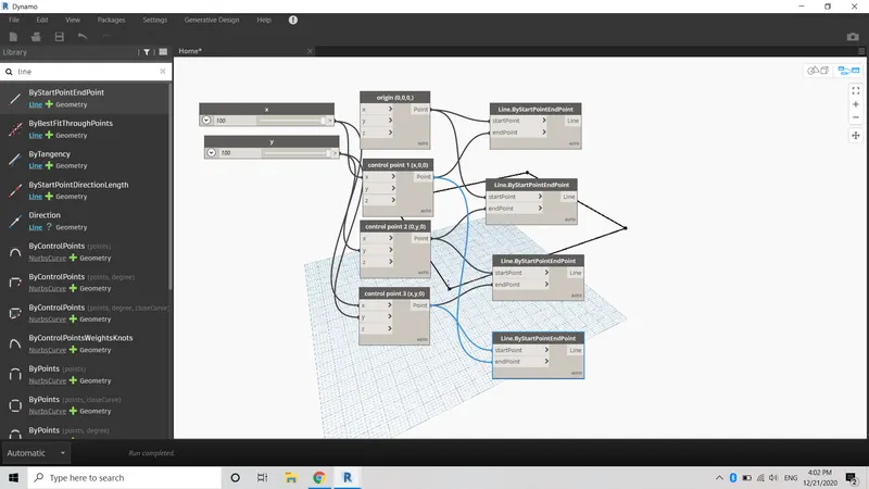
3) Rename it Origin and control point of 2,3
Step 2:
1) Create an integer slide and rename it as x and y
2) Edit the minimum and maximum values
3) Connect it with the points which we created.
Step 3:
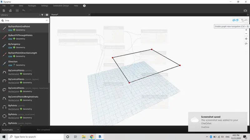
1) After creating the x and y integer slide switch it into 3d preview tab
2) 4 points have created in the dynamo
Step 4:
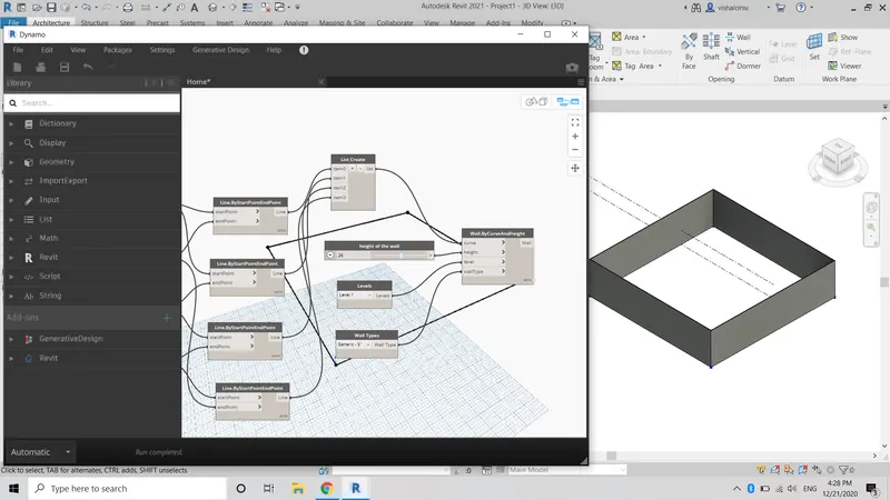
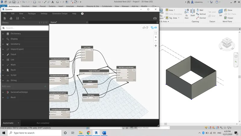
1) Now we need to join the 4 points and make it a wall
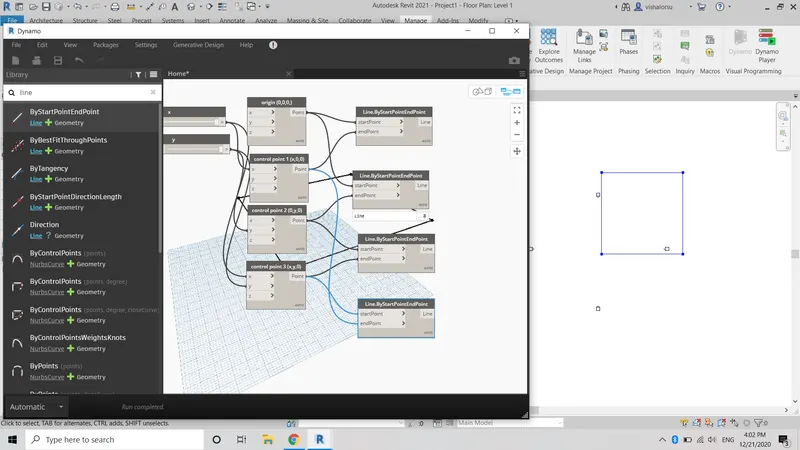
2) Create a Line and connect it with a point which we created
Step 5:
1) Now the points are connected by a line.
Step 6:
1) Now we need to make it as a wall
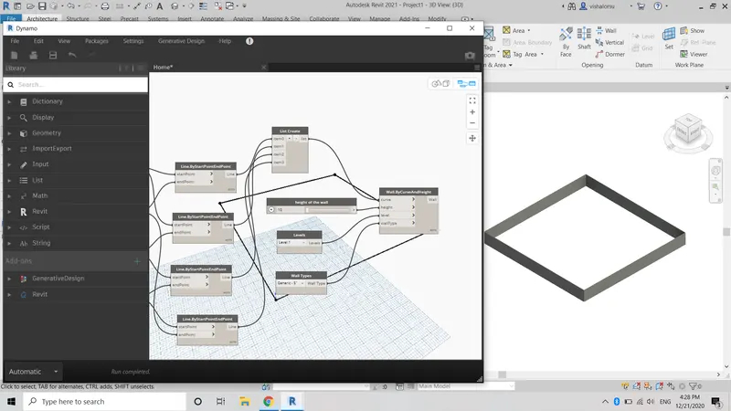
2) Create a wall type and choose the wall type as our wish
3) then connect it with a wall curve contains height, curve, wall type.
Result:
1) Wall has been created successfully
2) We can edit its height and width by adjusting the integer slide in dynamo
_______________________________________________________________________________________________________________________________________________________
3) Create an array of model elements in Revit. Use dynamo to vary the properties of model elements by using the slider or code block
Aim:
To create an array of model elements in Revit using dynamo to vary the properties of model elements by using the slider or code block
Tools used:
* Dynamo
* Rotate
* Column
Procedure:
Step 1:
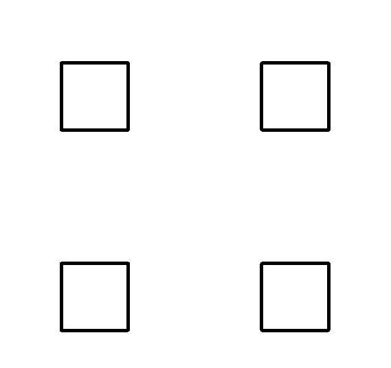
1) Open an architectural template
2) Place the 4 columns in both horizontal and vertical direction
Step 2:
1) Open a Dynamo tool by clicking the manage tab in the Revit application
2) Search Select model elements and insert them into the dynamo screen
3) In the select option select the elements which we created in Revit
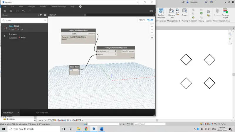
4) Create a code block and note the degree as 45
5) Create a family instance and connect it with degree and model elements
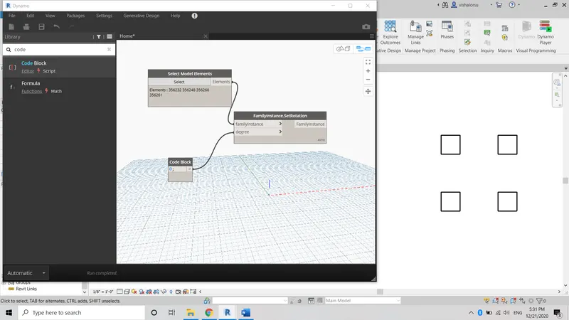
Step 3:
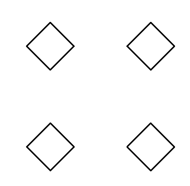
1) Switch the Revit application and the column will rotate exactly 45 degrees.
Result:
1) We can edit its Rotational degree by adjusting the integer slide in the dynamo
_______________________________________________________________________________________________________________________________________________________
4) Create a conceptual mass in Revit and develop a parametric column by dividing the surfaces and apply the concepts similar to those used in parametric walkway modelling. Use triangular bent or square-shaped panels to add the finish to the parametric column.
Aim:
To creating a conceptual mass in Revit and develop a parametric column by dividing the surfaces and apply the concepts similar to used in parametric walkway modeling.
Tools Used:
* Dynamo
* Divide surface
* curve
Procedure:
Step 1:
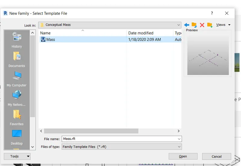
1) Create a new family
2) And choose a conceptual mass template
3) Select insert it into the Revit model
Step 2:
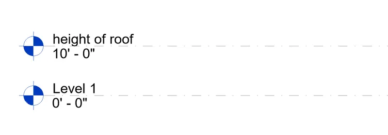
1) Set the level as considered it as roof height
Step 3:
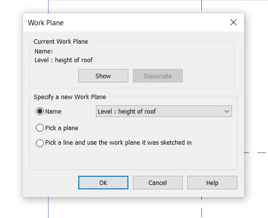
1) After creating the level set the work plane and click ok
Step 4:
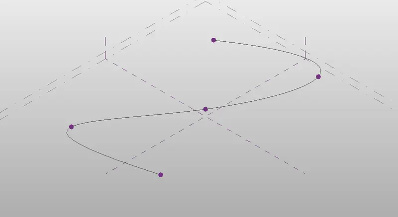
1) Switch it into 3d view
2) Create a curve using the point option
Step 5:
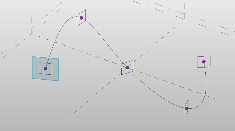
1) Click each point of the curve and change it as a set mode
2) Choose a polygon
3) Draw the polygon at each point in the curve
Step 6:
1) Click all the elements and choose the form option
2) Now the curve will turn into a surface
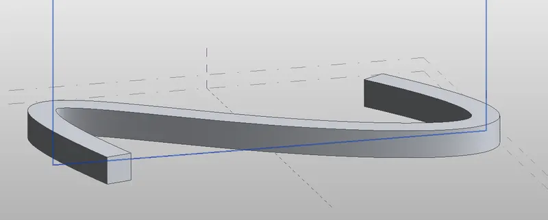
Step 7:
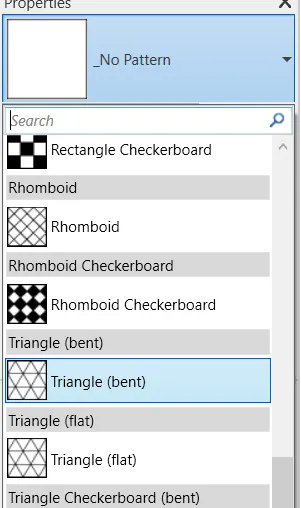
1) After creating the form option, click the Divide surface tool
2) Choose Triangular bent
3) Edit the values as 50 and 70.
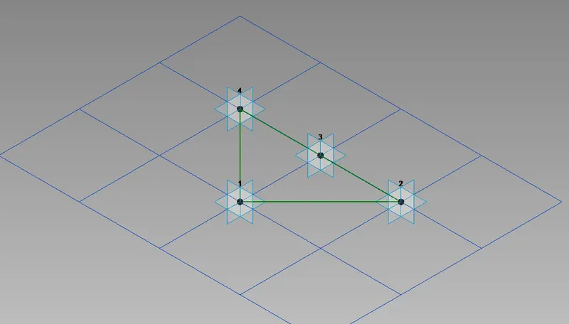
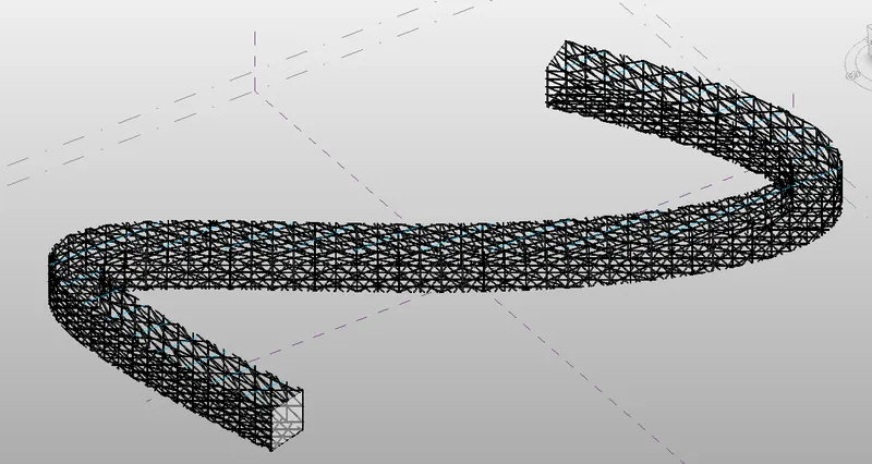
Result:
Thus the conceptual mass with a divided surface has been created successfully.
_______________________________________________________________________________________________________________________________________________________
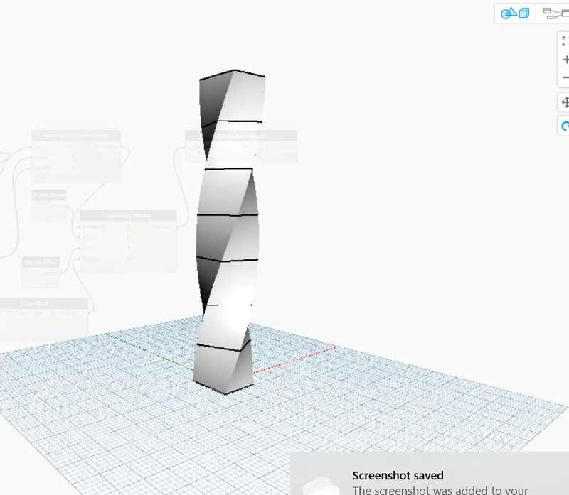
5) Use Dynamo to work on developing a Parametric Stadium. List your parameters and use the visual programming approach to complete the modeling, You can use the concepts discussed in parametric high rise tower in class for reference.
Aim:
To create a conceptual mass of parameters and the visual programming approach.
Tools Used:
* Dynamo
* Rectangle
* Rotate
Procedure:
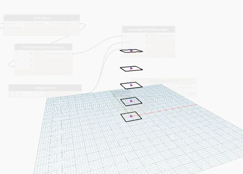
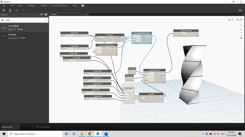
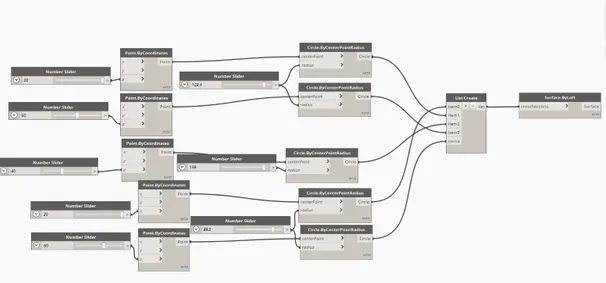
Step 1:
1) Open a Dynamo tool by clicking the manage tab in the Revit application
2) Create integer slides and rename them as levels, heights, top, and bottom floor rotation
Step 2:
1) Create a code block and edit as levels and floor heights
2) Connect the code block with levels and heights which we created
Step 3:
1) Create a rectangle slide
2) Connect it with coordinate by origin
3) Edit the width and length of the rectangle.
Step 4:
1) Insert rotate slide and set the degree of rotation
2) Connect the rotation slide with the surface loft
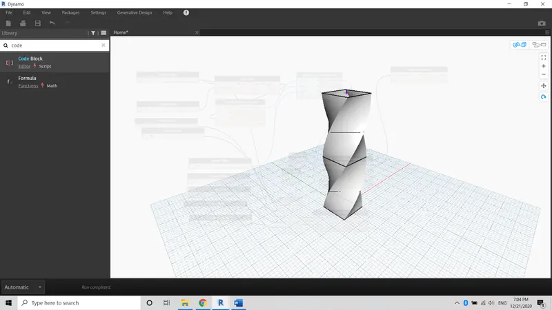
3) Switch the model into the 3d preview tool
Result:
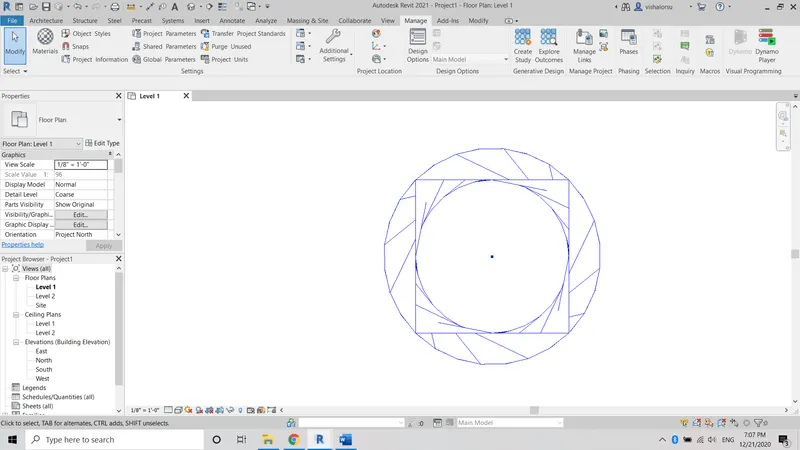
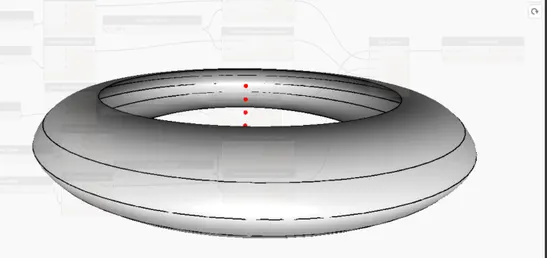
Thus the conceptual mass of visual programming of the model has been created successfully.
_______________________________________________________________________________________________________________________________________________________