REVIT_Creation of Basic Drawing_Week 2
1)
Building Information Modeling (BIM) is an intelligent 3D model-based process that gives architecture, engineering and construction professionals the insigt and tools to more efficiently plan, design, construct and manage buildings and infrastructure.
Features of using BIM oer 2D CAD tools are :-
- With te help of BIM we can achiee complete representation of the project.
- BIM is real time modeling. We can achieve changes in whole project by changing at one place.
- BIM is more time saving compared to 2D CAD.
2)
Category: Revit family falls into different categories like lighting fixtures, pipe fittings, etc.
Family: it is a group pd 2D and 3D information which are helpful in designing the project.
elements: the elements are controlled and defined by the families.
Instances: these are the items which will be available after installing the families.
AIM: go to insert tab and select a category, pick a family and element.
TOOLS USED: - insert tab.
- load family.
- file name.
- open
PROCEDURE:
1. Open revit and select architectural template.
2. Click on insert.
3. Select load family.
4. Load family dialog box will open.
5. Select the desired concept from te dialog box.
6. Click on open.
7. Go to window in architecture menu and select object.
8. Drag and click on place we want to insert component.
RESULT: Families and elements in project are selected.
3)
AIM: Open a project file with architectural template. Save the file with appropriate name. Set up the project units to Imperial / Metric based on your convenience of modelling. Complete the project information under Manage tab. Set up the maximum backups for project file to 3
TOOLS USED:
- New
- Save as
- Manage
- Project units
PROCEDURE:
- Open revit, click on new.
- click on architectural template.
- click on file menu and select save as and click on project.
- name the project and save it.
- click on manage menu and and change project units to imperial/metric.
- click on project information and fill the details.
- set maximum backups to 3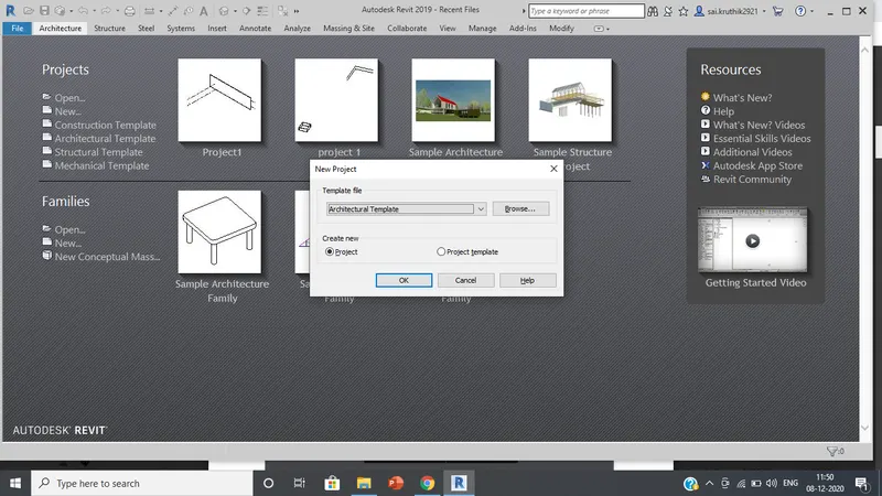
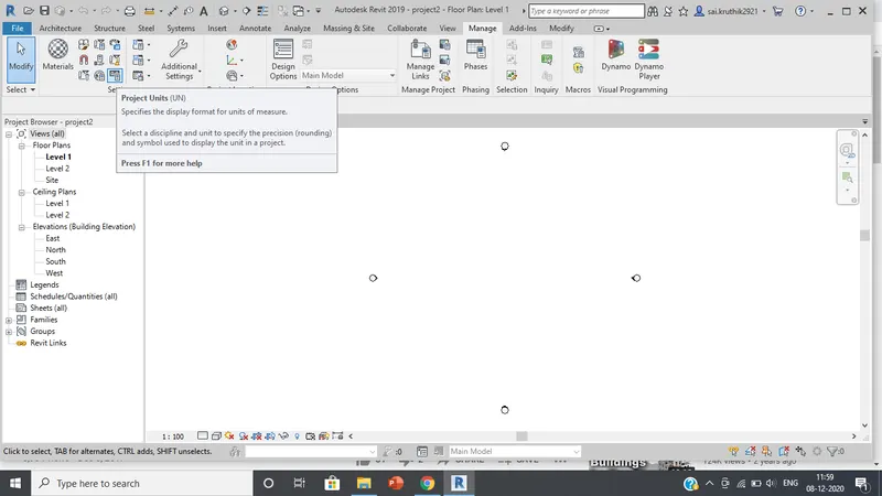
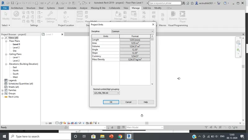
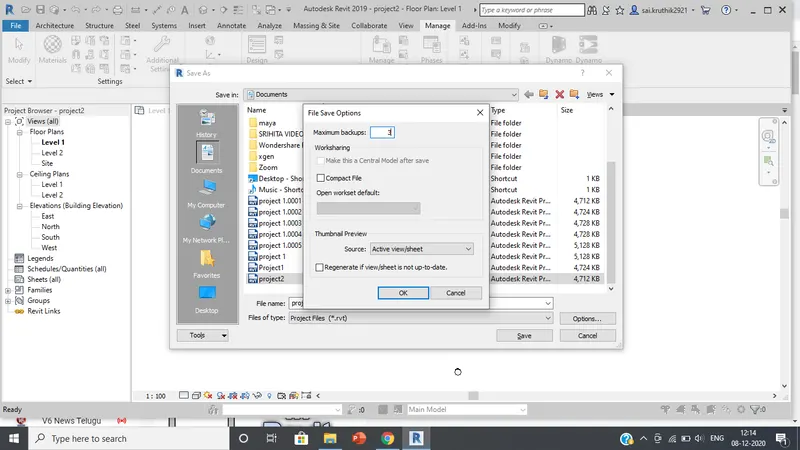
RESULT: project file with architectural template is opened and saved with appropriate name. Units are set to imperial/metric and maximum backups for project file is set to 3.
4)
CONCEPT OF LEVELS AND GRIDS...
Levels: levels are used to represent the floors in the elevation.
Grids: grids are used to reppresent all the walls with the help of horizontal and vertical lines and notations.
AIM:
Create the following Levels:
Ground Floor @ 0’
First Floor @ 10’
Second Floor @ 20’
Roof @ 30’
Grids Transverse Grids A, B,C,D, E @ 10’ spacing
Longitudinal Grids from 1 to 10 @ 20’ spacing
TOOLS USED:
- Grid.
- Levels.
PROCEDURE:
- select on architectural template and click on east under elevation.
- we will get elevation view, now rename and place levels at required level.
- we can add new level also.
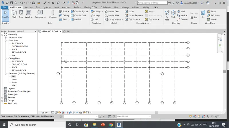
- now select ground floor.
- select grid tool under architectural menu.
- draw grid lines according to our requirement.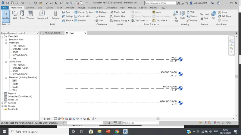
RESULT:
We get the different levels we want and grid of horizontal and vertical grid lines.
5)
AIM- 3D modelling of residential unit – From looking at your house / or a place you aspire. Create a conceptual layout of the residential unit.
TOOLS USED:
- Wall.
- View.
- Default 3D view.
PROCEDURE:
- open revit and select architecrural template and click ok.
- in architectural template select wall tool and start drawing the wall.
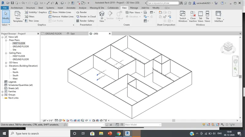
- after layout is drawn click on view menu and select Default 3D view.
- 3D view is obtained.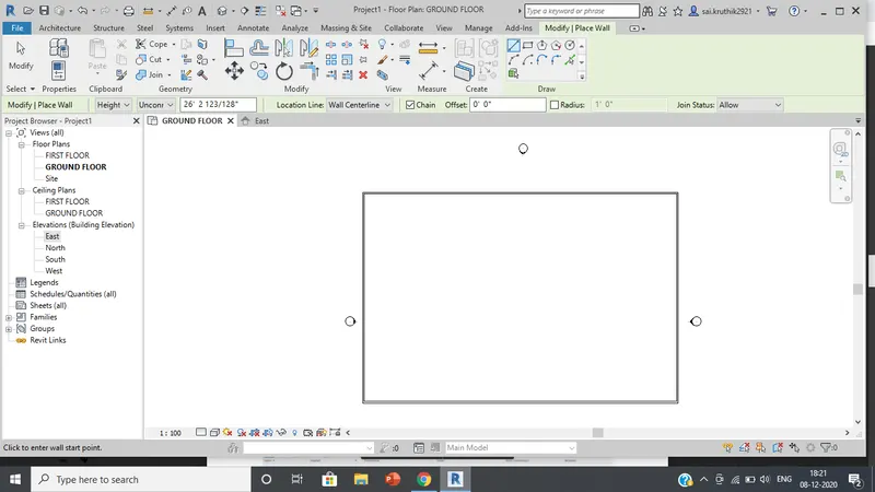
RESULT:
3D view of required layout is obtained.
6)
AIM: In the layout created draft the level of details you are planning to include – Dimensions of room, components you plan to add in the residential unit.
TOOL USED:
- Insert
- Load family
- Architecture
- Window
- Door
- View
- Default 3D view
PROCEDURE:
- layout is now completed.
- now with the help of wall tool draw inner walls in the layout.
- click on insert menu and select load family to add components.
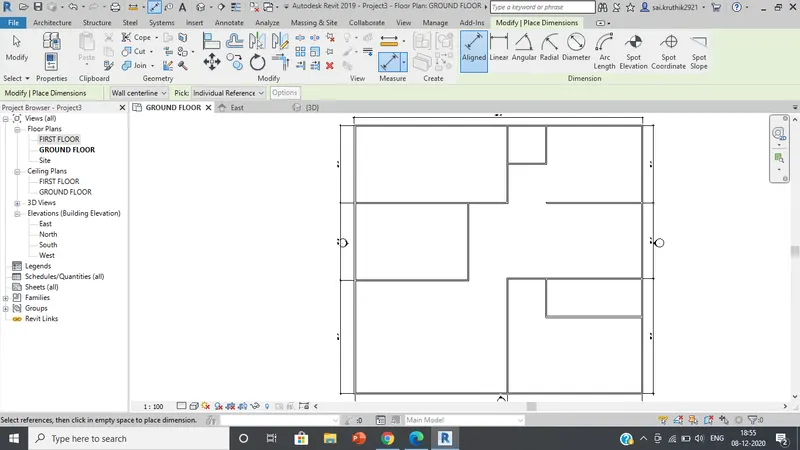
- from annotate menu select aligned option to add dimensions.
- click on view menu option and select default 3Diew to convert the project into 3D.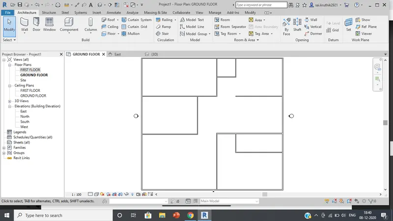
RESULT:
Layout of building with marked diensions with 3D view is obtained.
7)
AIM:
To add components to layout project like doors, window, tables, chairs, bed, lamps, from te insert library.
TOOLS USED:
- insert.
- Load family.
- View.
- Architecture.
- Doors.
- Windows.
- Components
- Bed.
- Dining table.
PROCEDURE:
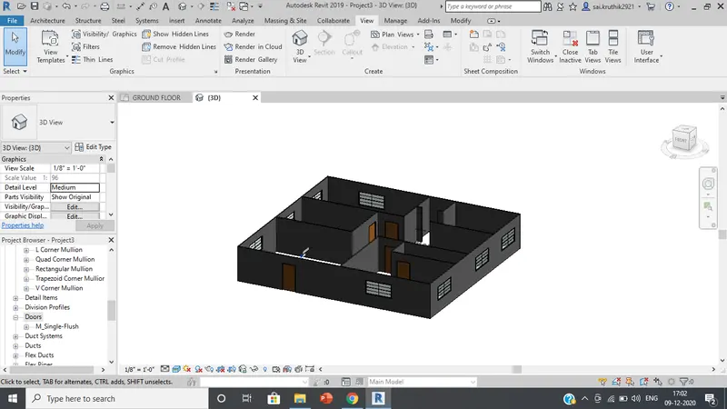
- after dimensions are given interior components are added.
- in insert menu we have load family we ave to load the reuired components.
- with the help of 3D view conver it into 3D.
RESULT:
Components are added to the building.